EP1467433A1 - Konverter für Satellitenrundfunkempfang - Google Patents
Konverter für Satellitenrundfunkempfang Download PDFInfo
- Publication number
- EP1467433A1 EP1467433A1 EP04007813A EP04007813A EP1467433A1 EP 1467433 A1 EP1467433 A1 EP 1467433A1 EP 04007813 A EP04007813 A EP 04007813A EP 04007813 A EP04007813 A EP 04007813A EP 1467433 A1 EP1467433 A1 EP 1467433A1
- Authority
- EP
- European Patent Office
- Prior art keywords
- package member
- converter
- main body
- satellite broadcasting
- broadcasting reception
- Prior art date
- Legal status (The legal status is an assumption and is not a legal conclusion. Google has not performed a legal analysis and makes no representation as to the accuracy of the status listed.)
- Withdrawn
Links
Images

Classifications
-
- H—ELECTRICITY
- H05—ELECTRIC TECHNIQUES NOT OTHERWISE PROVIDED FOR
- H05K—PRINTED CIRCUITS; CASINGS OR CONSTRUCTIONAL DETAILS OF ELECTRIC APPARATUS; MANUFACTURE OF ASSEMBLAGES OF ELECTRICAL COMPONENTS
- H05K5/00—Casings, cabinets or drawers for electric apparatus
- H05K5/06—Hermetically-sealed casings
- H05K5/068—Hermetically-sealed casings having a pressure compensation device, e.g. membrane
-
- H—ELECTRICITY
- H01—ELECTRIC ELEMENTS
- H01Q—ANTENNAS, i.e. RADIO AERIALS
- H01Q1/00—Details of, or arrangements associated with, antennas
- H01Q1/12—Supports; Mounting means
- H01Q1/22—Supports; Mounting means by structural association with other equipment or articles
- H01Q1/24—Supports; Mounting means by structural association with other equipment or articles with receiving set
- H01Q1/247—Supports; Mounting means by structural association with other equipment or articles with receiving set with frequency mixer, e.g. for direct satellite reception or Doppler radar
-
- H—ELECTRICITY
- H01—ELECTRIC ELEMENTS
- H01Q—ANTENNAS, i.e. RADIO AERIALS
- H01Q1/00—Details of, or arrangements associated with, antennas
- H01Q1/42—Housings not intimately mechanically associated with radiating elements, e.g. radome
-
- H—ELECTRICITY
- H01—ELECTRIC ELEMENTS
- H01Q—ANTENNAS, i.e. RADIO AERIALS
- H01Q13/00—Waveguide horns or mouths; Slot antennas; Leaky-waveguide antennas; Equivalent structures causing radiation along the transmission path of a guided wave
- H01Q13/02—Waveguide horns
-
- H—ELECTRICITY
- H01—ELECTRIC ELEMENTS
- H01Q—ANTENNAS, i.e. RADIO AERIALS
- H01Q19/00—Combinations of primary active antenna elements and units with secondary devices, e.g. with quasi-optical devices, for giving the antenna a desired directional characteristic
- H01Q19/10—Combinations of primary active antenna elements and units with secondary devices, e.g. with quasi-optical devices, for giving the antenna a desired directional characteristic using reflecting surfaces
- H01Q19/12—Combinations of primary active antenna elements and units with secondary devices, e.g. with quasi-optical devices, for giving the antenna a desired directional characteristic using reflecting surfaces wherein the surfaces are concave
- H01Q19/13—Combinations of primary active antenna elements and units with secondary devices, e.g. with quasi-optical devices, for giving the antenna a desired directional characteristic using reflecting surfaces wherein the surfaces are concave the primary radiating source being a single radiating element, e.g. a dipole, a slot, a waveguide termination
- H01Q19/132—Horn reflector antennas; Off-set feeding
Definitions
- the present invention relates to a converter for satellite broadcasting reception to receive a satellite broadcast.
- a circuit board (not shown) comprising a desired circuit (receiving circuit) is accommodated.
- the main body 51 is provided with a horn portion 52 and female coaxial connectors 53 in a state of being protruding to the outside of the main body.
- a cover 54 made of a synthetic resin molding is attached to the main body 51 to cover the main body 51 and the connectors 53, and male coaxial connectors 55 are connected to the connectors 53.
- the connectors 55 leads a satellite broadcast from the converter for satellite broadcasting reception, which is located outdoors, is electrically connected to a tuner (not shown) located indoors.
- the cover 54 of the converter for satellite broadcasting reception which is located outdoors, provides waterproof protection of the main body 51 and the connector 53 (for example, see Japanese Unexamined Patent Application Publication No. 11-46149).
- the converter for satellite broadcasting reception comprises a main body 61, connectors 62, and a horn portion (not shown).
- the entire converter for satellite broadcasting reception is covered with a package member 63, creating a sealed state, wherein such package member 63 is made of an insulating material (for example, see Japanese Unexamined Patent Application Publication No. 5-327320).
- the conventional converter for satellite broadcasting reception is made to be waterproof by way of the package member 63 until the converter is shipped from a manufacturing factory to an end user (about several months). Upon receipt of the package member 63, the end user tears the package member 63 to pieces and then takes the converter for satellite broadcasting reception out of the package member. The converter for satellite broadcasting reception is then placed outdoors.
- the converter for satellite broadcasting reception which is placed outdoors, has a structure that is not sufficiently waterproof, it is required that the converter for satellite broadcasting reception have a waterproof structure such as a cover.
- the converter When the conventional converter for satellite broadcasting reception is employed outdoors, the converter is used after taking it out of a waterproof structure, such as the cover 54, or the package member. As a result, it is difficult to ensure sufficient waterproofness, and it is required that strict bonding work of the cover 54 be performed. Accordingly, there is a problem in that productivity thereof deteriorates and the cost thereof increases.
- a converter for satellite broadcasting reception comprises: a main body in which a circuit board is accommodated; a horn portion protruding from the main body; connectors protruding from the main body; and a package member made of a flexible insulating material, wherein the package member, which is in a sealed state, accommodates the main body and the horn portion, with at least parts of the connectors being exposed to the outside of the package member.
- the converter for satellite broadcasting reception further comprises a cover made of a synthetic resin molding, wherein the outer peripheral portion of the package member is covered with the cover.
- the entire outer peripheral portion of the package member is covered with the cover.
- a deflation process is carried out in the inside of the package member.
- a seam of the package member and/or a joint between the package member and the connectors are bonded by thermocompression.
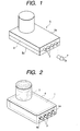
- Fig. 1 is a perspective view illustrating a converter for satellite broadcasting reception according to the present invention.
- Fig. 2 is a perspective view illustrating a converter for satellite broadcasting reception, according to the present invention, in a state in which a cover is detached.
- a configuration of a converter for satellite broadcasting reception according to the present invention will be described with reference to Fig. 1 and Fig. 2.
- a circuit board (not shown) comprising a desired circuit (receiving circuit) is accommodated.
- the horn portion 2 in a state in which a horn portion 2 protrudes from the upper portion of the main body 1 to the outside thereof, the horn portion 2 is combined with the main body 1, and, in a state in which a plurality of female coaxial connectors 3 protrude from the lateral side of the main body 1 to the outside thereof, the connectors 3 are combined with the main body 1.
- a package member 4 which is made of flexible, plastic insulating materials such as polyester, nylon, polypropylene, etc., forms a bag shape.
- the package member 4 covers the main body 1 and the horn portion 2, with at least parts (tips) of the connectors 3 being exposed to the outside, and the inside of the package member 4, in which the main body 1 and the horn portion 2 are accommodated, is in a sealed state.
- a deflation process is carried out in the inside of the package member 4, in which the main body 1 and the horn portion 2 are accommodated. Further, a seam (not shown) of the package member 4 and a joint 4a between the package member 4 and the connectors 3 are bonded by thermocompression.
- the package member 4 is bonded by thermocompression, it may be bonded with an adhesive.
- a cover 5 made of a synthetic resin molding, includes a first cover 5a for covering the upper portion of the main body 1 and the horn portion 2, and a second cover 5b for covering the lower portion of the main body 1.
- the cover 5 covers the entire outer peripheral portion of the package member 4, and covers the main body 1 and the horn portion 2, with part of the connectors 3 protruding to the outside of the cover 5.
- an adhesive 6 is applied to a joint, which is a seam between the first and second covers 5a, 5b, and then the first and second covers 5a, 5b are combined with each other.
- the cover 5 prevents the package member 4 from breaking due to external force.
- the adhesive 6 for combining the first and second covers 5a, 5b with each other is not applied sufficiently, the package member 4 provides sufficient waterproofness for the main body 1 or the horn portion 2.
- the cover 5 does not require strict bonding work, but requires only simple bonding work for combining the first and second covers 5a, 5b with each other.
- cover 5 is not limited thereto, and a variety of configurations may be employed.
- the converter for satellite broadcasting reception according to the present invention is formed according to the above configuration, the converter for satellite broadcasting reception is placed outdoors, and male coaxial connectors 7 are connected to the connectors 3. As a result, the connectors 7 leads a satellite broadcast from the converter for satellite broadcasting reception, which is located outdoors, to a tuner (not shown) located indoors.
- the converter for satellite broadcasting reception according to the present invention is made to be waterproof by way of the package member 63 until it is shipped from a manufacturing factory to an end user(several months), with the converter being protected by the package member 4 and the cover 5.
- the converter for satellite broadcasting reception is placed outdoors, with the converter being protected by the package member 4 and the cover 5.
- the entire package member 4 may be protected by the cover 5, only a part of the package member 4 may be protected by the cover 5, or the cover 5 may be eliminated as needed.
- the converter for satellite broadcasting reception comprises a main body in which a circuit board is accommodated; a horn portion protruding from the main body; connectors protruding from the main body; and a package member made of a flexible insulating material.
- the package member which is in a sealed state, accommodates the main body and the horn portion, with at least parts of the connectors being exposed to the outside of the package member.
- the present invention does not require the conventional strict bonding work to bond the covers to each other, and therefore it is possible to obtain the converter with high-productivity at a low cost.
- the converter for satellite broadcasting reception comprises a cover made of a synthetic resin molding, and the outer peripheral portion of the package member is covered with the cover.
- the cover does not require a strict bonding work, but requires only simple bonding work.
- the entire outer peripheral portion of the package member is covered with the cover. As a result, it is possible to prevent the package member from breaking due to external force and it is possible to ensure a waterproof structure.
- a seam of the package member and/or a joint between the package member and the connectors are bonded by thermocompression.
- the work thereof is simple and is excellent in productivity.
Landscapes
- Engineering & Computer Science (AREA)
- Radar, Positioning & Navigation (AREA)
- Remote Sensing (AREA)
- Microelectronics & Electronic Packaging (AREA)
- Details Of Aerials (AREA)
- Structure Of Receivers (AREA)
- Casings For Electric Apparatus (AREA)
- Waveguide Aerials (AREA)
Applications Claiming Priority (2)
| Application Number | Priority Date | Filing Date | Title |
|---|---|---|---|
| JP2003106714A JP2004312622A (ja) | 2003-04-10 | 2003-04-10 | 衛星放送受信用コンバータ |
| JP2003106714 | 2003-04-10 |
Publications (1)
| Publication Number | Publication Date |
|---|---|
| EP1467433A1 true EP1467433A1 (de) | 2004-10-13 |
Family
ID=32866773
Family Applications (1)
| Application Number | Title | Priority Date | Filing Date |
|---|---|---|---|
| EP04007813A Withdrawn EP1467433A1 (de) | 2003-04-10 | 2004-03-31 | Konverter für Satellitenrundfunkempfang |
Country Status (2)
| Country | Link |
|---|---|
| EP (1) | EP1467433A1 (de) |
| JP (1) | JP2004312622A (de) |
Cited By (2)
| Publication number | Priority date | Publication date | Assignee | Title |
|---|---|---|---|---|
| CN100479335C (zh) * | 2005-12-31 | 2009-04-15 | 启碁科技股份有限公司 | 卫星接受器的壳体与形成的方法 |
| CN100561879C (zh) * | 2005-10-21 | 2009-11-18 | 启碁科技股份有限公司 | 具有遮雨盖的卫星接收器 |
Citations (4)
| Publication number | Priority date | Publication date | Assignee | Title |
|---|---|---|---|---|
| WO1996027279A1 (en) * | 1995-03-02 | 1996-09-06 | N.V. Raychem S.A. | Sealed packaging for environmental protection of electronics |
| US5739463A (en) * | 1994-04-11 | 1998-04-14 | Raychem Corporation | Sealed electronic packaging for environmental protection of active electronics |
| EP1128462A2 (de) * | 2000-02-25 | 2001-08-29 | Alps Electric Co., Ltd. | Wasserdichte und gasdurchlässige Gehäusekonstruktion für Satellitenempfangskonverter |
| US20020180656A1 (en) * | 2001-05-30 | 2002-12-05 | Pecora Ronald A. | Low profile antenna |
-
2003
- 2003-04-10 JP JP2003106714A patent/JP2004312622A/ja not_active Withdrawn
-
2004
- 2004-03-31 EP EP04007813A patent/EP1467433A1/de not_active Withdrawn
Patent Citations (4)
| Publication number | Priority date | Publication date | Assignee | Title |
|---|---|---|---|---|
| US5739463A (en) * | 1994-04-11 | 1998-04-14 | Raychem Corporation | Sealed electronic packaging for environmental protection of active electronics |
| WO1996027279A1 (en) * | 1995-03-02 | 1996-09-06 | N.V. Raychem S.A. | Sealed packaging for environmental protection of electronics |
| EP1128462A2 (de) * | 2000-02-25 | 2001-08-29 | Alps Electric Co., Ltd. | Wasserdichte und gasdurchlässige Gehäusekonstruktion für Satellitenempfangskonverter |
| US20020180656A1 (en) * | 2001-05-30 | 2002-12-05 | Pecora Ronald A. | Low profile antenna |
Cited By (2)
| Publication number | Priority date | Publication date | Assignee | Title |
|---|---|---|---|---|
| CN100561879C (zh) * | 2005-10-21 | 2009-11-18 | 启碁科技股份有限公司 | 具有遮雨盖的卫星接收器 |
| CN100479335C (zh) * | 2005-12-31 | 2009-04-15 | 启碁科技股份有限公司 | 卫星接受器的壳体与形成的方法 |
Also Published As
| Publication number | Publication date |
|---|---|
| JP2004312622A (ja) | 2004-11-04 |
Similar Documents
| Publication | Publication Date | Title |
|---|---|---|
| EP1671397B1 (de) | Abdeckungsstruktur für ein funkgerät | |
| US5249236A (en) | Wiring structure of loudspeaker | |
| US20140132768A1 (en) | Camera for car | |
| JP3195263B2 (ja) | 防水コネクタおよびその製造方法 | |
| JP2624198B2 (ja) | アンテナ内蔵型携帯用無線機 | |
| US11165193B2 (en) | Electrical connection structure and wearable device | |
| EP1467433A1 (de) | Konverter für Satellitenrundfunkempfang | |
| JP3926221B2 (ja) | フィルムアンテナ用接続端子構造 | |
| CN101752651A (zh) | 电路基板支撑构造以及天线装置 | |
| WO2002065579A1 (fr) | Antenne de vehicule | |
| JP2692666B2 (ja) | 衛星放送受信用コンバータ | |
| JPH11168023A (ja) | コンデンサ | |
| US6261110B1 (en) | Converter for receiving satellite broadcasting having extensible/retractable waterproof cover attached at its junction portion | |
| US5238431A (en) | Self securing electrical contact assembly | |
| US10505266B2 (en) | Antenna device | |
| US20100230262A1 (en) | Panel mount sealed pushbutton switch | |
| WO2012114732A1 (ja) | ワイヤハーネスにおける短絡回路の形成方法 | |
| EP2634861B1 (de) | Folienantennenvorrichtung | |
| JP2004048418A (ja) | 衛星放送受信用コンバータ | |
| CN117044046A (zh) | 布线部件 | |
| JP3961931B2 (ja) | 電子機器収納ケース | |
| JPH08186417A (ja) | アンテナ接合具 | |
| US6506062B1 (en) | Circuit board having an integrated circuit board connector and method of making the same | |
| US20020084096A1 (en) | Electric wire coupling assembly | |
| JP2004023525A (ja) | 自動車用窓ガラスアンテナ装置 |
Legal Events
| Date | Code | Title | Description |
|---|---|---|---|
| PUAI | Public reference made under article 153(3) epc to a published international application that has entered the european phase |
Free format text: ORIGINAL CODE: 0009012 |
|
| AK | Designated contracting states |
Kind code of ref document: A1 Designated state(s): AT BE BG CH CY CZ DE DK EE ES FI FR GB GR HU IE IT LI LU MC NL PL PT RO SE SI SK TR |
|
| AX | Request for extension of the european patent |
Extension state: AL LT LV MK |
|
| 17P | Request for examination filed |
Effective date: 20041026 |
|
| 17Q | First examination report despatched |
Effective date: 20050214 |
|
| AKX | Designation fees paid |
Designated state(s): DE FI FR GB SE |
|
| STAA | Information on the status of an ep patent application or granted ep patent |
Free format text: STATUS: THE APPLICATION IS DEEMED TO BE WITHDRAWN |
|
| 18D | Application deemed to be withdrawn |
Effective date: 20050625 |