EP1128621A2 - Synchronisation de la porteuse et de l'horloge de symboles pour signaux modulés par sauts de phase différentiels à 8 états (8-DPSK) - Google Patents
Synchronisation de la porteuse et de l'horloge de symboles pour signaux modulés par sauts de phase différentiels à 8 états (8-DPSK) Download PDFInfo
- Publication number
- EP1128621A2 EP1128621A2 EP01102125A EP01102125A EP1128621A2 EP 1128621 A2 EP1128621 A2 EP 1128621A2 EP 01102125 A EP01102125 A EP 01102125A EP 01102125 A EP01102125 A EP 01102125A EP 1128621 A2 EP1128621 A2 EP 1128621A2
- Authority
- EP
- European Patent Office
- Prior art keywords
- coded signal
- samples
- doppler
- frequency
- preamble
- Prior art date
- Legal status (The legal status is an assumption and is not a legal conclusion. Google has not performed a legal analysis and makes no representation as to the accuracy of the status listed.)
- Withdrawn
Links
- 238000000034 method Methods 0.000 claims abstract description 14
- 230000004044 response Effects 0.000 claims description 11
- 238000001914 filtration Methods 0.000 claims description 5
- 238000000926 separation method Methods 0.000 claims description 5
- 238000005070 sampling Methods 0.000 claims description 3
- 238000011084 recovery Methods 0.000 claims 2
- 230000003111 delayed effect Effects 0.000 abstract description 4
- 230000008569 process Effects 0.000 abstract description 4
- 239000000523 sample Substances 0.000 description 16
- 230000006870 function Effects 0.000 description 4
- 238000001514 detection method Methods 0.000 description 3
- 238000006243 chemical reaction Methods 0.000 description 2
- 230000003247 decreasing effect Effects 0.000 description 2
- 238000010586 diagram Methods 0.000 description 2
- 230000010363 phase shift Effects 0.000 description 2
- 230000033228 biological regulation Effects 0.000 description 1
- 230000005540 biological transmission Effects 0.000 description 1
- 230000003139 buffering effect Effects 0.000 description 1
- 230000001934 delay Effects 0.000 description 1
- 230000009977 dual effect Effects 0.000 description 1
- 230000008520 organization Effects 0.000 description 1
- 230000009467 reduction Effects 0.000 description 1
- 230000001105 regulatory effect Effects 0.000 description 1
- 239000012723 sample buffer Substances 0.000 description 1
- 230000008054 signal transmission Effects 0.000 description 1
- 230000001629 suppression Effects 0.000 description 1
Images


Classifications
-
- H—ELECTRICITY
- H04—ELECTRIC COMMUNICATION TECHNIQUE
- H04L—TRANSMISSION OF DIGITAL INFORMATION, e.g. TELEGRAPHIC COMMUNICATION
- H04L27/00—Modulated-carrier systems
- H04L27/18—Phase-modulated carrier systems, i.e. using phase-shift keying
- H04L27/22—Demodulator circuits; Receiver circuits
- H04L27/233—Demodulator circuits; Receiver circuits using non-coherent demodulation
-
- H—ELECTRICITY
- H04—ELECTRIC COMMUNICATION TECHNIQUE
- H04L—TRANSMISSION OF DIGITAL INFORMATION, e.g. TELEGRAPHIC COMMUNICATION
- H04L27/00—Modulated-carrier systems
- H04L27/0014—Carrier regulation
- H04L2027/0024—Carrier regulation at the receiver end
- H04L2027/0026—Correction of carrier offset
- H04L2027/003—Correction of carrier offset at baseband only
-
- H—ELECTRICITY
- H04—ELECTRIC COMMUNICATION TECHNIQUE
- H04L—TRANSMISSION OF DIGITAL INFORMATION, e.g. TELEGRAPHIC COMMUNICATION
- H04L27/00—Modulated-carrier systems
- H04L27/0014—Carrier regulation
- H04L2027/0024—Carrier regulation at the receiver end
- H04L2027/0026—Correction of carrier offset
- H04L2027/0036—Correction of carrier offset using a recovered symbol clock
-
- H—ELECTRICITY
- H04—ELECTRIC COMMUNICATION TECHNIQUE
- H04L—TRANSMISSION OF DIGITAL INFORMATION, e.g. TELEGRAPHIC COMMUNICATION
- H04L27/00—Modulated-carrier systems
- H04L27/0014—Carrier regulation
- H04L2027/0044—Control loops for carrier regulation
- H04L2027/0046—Open loops
-
- H—ELECTRICITY
- H04—ELECTRIC COMMUNICATION TECHNIQUE
- H04L—TRANSMISSION OF DIGITAL INFORMATION, e.g. TELEGRAPHIC COMMUNICATION
- H04L27/00—Modulated-carrier systems
- H04L27/0014—Carrier regulation
- H04L2027/0044—Control loops for carrier regulation
- H04L2027/0063—Elements of loops
- H04L2027/0065—Frequency error detectors
-
- H—ELECTRICITY
- H04—ELECTRIC COMMUNICATION TECHNIQUE
- H04L—TRANSMISSION OF DIGITAL INFORMATION, e.g. TELEGRAPHIC COMMUNICATION
- H04L27/00—Modulated-carrier systems
- H04L27/0014—Carrier regulation
- H04L2027/0083—Signalling arrangements
- H04L2027/0089—In-band signals
- H04L2027/0093—Intermittant signals
- H04L2027/0095—Intermittant signals in a preamble or similar structure
Definitions
- VHF radios must include a mode of operation which has D8PSK (differential 8 phase shift keying) modulation, in accordance with International Commercial Aviation Organization (ICAO) Mode 2 waveform specification.
- D8PSK differential 8 phase shift keying
- IAO International Commercial Aviation Organization
- the received radio signal may be corrupted by carrier frequency offset (Doppler) of up to + or - 1800 Hz due to relative path motion plus relative transmit - receive frequency uncertainty.
- Doppler carrier frequency offset
- the preferred embodiment is useful in a radio receiver adapted to receive a carrier signal having a Doppler shifted frequency.
- the carrier signal carries a coded signal having variable amplitude and phase which represents symbols coded by phase.
- the symbols are divided into a preamble portion having a predetermined code and a message portion.
- the preferred embodiment processes the coded signal by storing samples of the coded signal representing at least some of the predetermined symbols of the preamble.
- the stored samples have variable amplitudes and are divided into a plurality of sample groups.
- One sample group of the various sample groups is identified as having a predetermined amplitude relationship with respect to other of the sample groups.
- the samples of the coded signal are selected in response to the identification of the one sample group.
- the Doppler frequency of the selected samples is estimated, and the message portion of the coded signal is delayed while the identifying, selecting and estimating proceeds.
- the Doppler frequency of the coded signal is reduced in response to the estimated Doppler frequency in order to generate a Doppler reduced coded signal.
- the Doppler reduced coded signal is filtered in a filter matched only to the transmitted message, but including carrier offset, and the message portion is demodulated in response to the Doppler reduced coded signal.
- the storing of the samples preferably is carried out by digital memory and the remaining portions of the above-described technique are preferably carried out by a digital processor.
- an incoming message may be detected in a noisy background and any Doppler frequency present may be efficiently estimated.
- the technique is robust in time varying channels and is very efficient and conservative of processor time.
- Figure 1 is a schematic and functional block diagram of a preferred form of radio receiver embodying the invention.
- Figure 2 is a functional diagram of a preferred form of the Doppler estimate referred to in Figure 1.
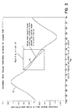
- Figure 3 is a graph illustrating a preferred form of interpolation used in connection with the Doppler estimate illustrated in Figure 2.
- a preferred form of radio receiver 10 is adapted to receive a carrier signal having a Doppler shifted frequency and carrying a coded signal having a variable amplitude and phase.
- the coded signal represents symbols coded by phase which are divided into a preamble portion having a predetermined code and a message portion in which the coding varies in order to transmit information.
- Coding is in the form of D8PSK phase shift keying modulation.
- the coding is received at a symbol rate of 10.5K symbols per second.
- the carrier signals are received by a conventional antenna (not shown), and are down converted to an intermediate frequency (IF) carrier which still carries the coded signal representing the D8PSK coding.
- IF intermediate frequency
- the IF carrier is received at an input 12 and is converted to digital form via a conventional analog to digital converter 14 operating at 50 MSPS (megasamples per second).
- the converted digital IF signal is received by a logic unit 16 which may be in the form of a digital signal processor that performs various operations described in the remaining blocks shown in Figure 1. For example, in block 18, the processor filters the digital 50 MSPS IF signal to + or - 21K Hz, down converts the IF digital signal to baseband frequency and resamples the baseband frequency to generate orthogonal I and Q signals at a rate of 105 KSPS.
- the processor also may perform data output buffering in operation 18.
- the signal generated by operation 18 is converted in operation 20 to a floating point signal still having a rate of 105 KSPS.
- the floating point conversion operation converts 13 bits of signed integer value and 3 bits of decimal position to create a virtual 20 bit signal which is then converted to a floating point format.
- the output of the floating point conversion operation is received along a signal path 21 by a message detect operation 22.
- Operation 22 declares that a message has been detected when the received power referenced to the antenna input port exceeds -102 dBm.
- Message operation 22 is used to detect only the preamble portion of the coded signal.
- the next 180 samples of the coded signal are stored in memory 23 for use in initializing symbol synchronization and Doppler acquisition.
- the sampling resulting in the 180 samples is carried out at 105 KSPS which is 10 times the symbol rate of 10.5 KSPS.
- 10 samples are stored for each of the symbols in the preamble.
- the envelope of the samples stored in memory 23 are approximated.
- the phase information in the 180 stored samples is ignored and the amplitude information is at least approximated.
- the amplitude information from the 180 samples received from operation 24 is used to divide the samples into 10 groups, 1 for each of the 10 possible sample phases.
- the groups consist of 1 sample from each of the 18 symbols, forming ten different decimate by 10 groups.
- the first sample from each of the 18 symbols forms a first group and the second sample from each of the 18 symbols forms a second group, etc.
- the groups are compared to determine the one with minimum variation of envelope amplitude.
- the minimum variation is determined by estimating the minimum standard deviation among the groups.
- Each of the ten samples for each of the symbols stored in memory 23 is fed in time sequential fashion to a shift register 28 comprising flip flops F1 - F10.
- the flip flop holding the sample from the group having the minimum variation is conducted over a path 31 and the two adjacent samples are transmitted over paths 30 and 32.
- the relationship of paths 30-32 to flip flops F1 - F10 varies depending on which group of samples is estimated to have the minimum variation of amplitude.
- Shift register 28 may be in the form of a continuous loop so that the information transmitted to path 31 may jump from flip flop F10 to flip flop F1 (and vice versa) depending on the sample group determined to have the minimum variation of amplitude.
- the transmission of signals from flip flops F1 - F10 to paths 30 - 32 is controlled in a well known manner by a symbol tracking loop 50 which receives the identification of the group having the minimum variation of amplitude from operation 26 over a path 27.
- the signals on paths 30 - 32 are transmitted to decimators 40 - 42, respectively.
- Loop 50 interpolates between the information from decimators 40 - 42 in order to generate a signal on a path 51 indicating which of the sample groups in memory 23 most accurately tracks the symbols coded into the coded signal received on path 21.
- the signal on path 51 also is sent over another path 52.
- Symbol tracking loop 50 tracks symbol drift due to the changing link delay due to aircraft motion. Correct sample timing can be maintained to an accuracy of less than 9.5 microseconds with a symbol drift rate of 4.28 samples/second (1 sample phase/2454 symbols). The symbol tracking loop is capable of tracking a constant symbol drift rate of 1 +/- 10 symbols/second.
- the samples stored in memory 23 are filtered in a divide by ten finite impulse response filter 60 which has a -3 decibel attenuation at 8.5 KHz and a -30 decibel attenuation at 15 KHz.
- the information on path 51 indicates to filter 60 the group of samples stored in memory 23 which are selected and passed onto path 68.
- the group determined by operations 26 and 50 to have the minimum variation of amplitude is the group selected by filter 60 for transmission on path 68 to a Doppler estimator 70.
- Doppler estimator 70 includes a correlation bank 71 which may form part of memory 23.
- Correlator bank 71 stores 21 frequency shifted versions of the code for the transmitted complex preamble of the Mode 2 message received on path 21 as correlation reference signals. Each of the stored correlation reference signals is identical except for a frequency shift.
- the stored correlation signals are compared with the samples received on path 68, and the stored correlation signal corresponding most closely to the samples received on path 68 is identified in operation 72.
- the maximum row index I and two adjacent indices are identified.
- the stored correlation signal having maximum correlation and the two adjacent correlation signals having frequencies closest to the maximum correlation signal are identified in operation 73.
- the values of a Doppler frequency identified in operation 73 are used as the basis for interpolation in operation 74.
- the interpolation is carried out by an inverse hyperbolic tangent function as shown in Figure 3.
- the Doppler present on the received D8PSK signal can be estimated by operation 70 to an accuracy of better than +/- 50 Hz. With inverse hyperbolic interpolation, an accuracy better than 10 Hz can be achieved.
- N e.g., 21
- This produces a set of correlator outputs from which threshold comparison yields symbol sync. If processing intensity was not limited, this type of process could be used for detection, as well. Here it can be used for a false alarm suppression by verifying that the detected message has a large peak-sidelobe correlation output.
- the maximum value and two adjacent frequency bin readings yields three correlator values, P_, Po, P+.
- a unique interpolation linearizing algorithm is used here which passes the linear estimate (P+-P-)/Po through a hyperbolic tangent function producing a near linear frequency interpolation over the range of the cell having the highest correlation.
- the message detection is very robust since it integrates energy over 16 symbols and due to the complex reference, also will fight narrowband interference (BW ⁇ 8kHz) since some anti-jam processing gain is achieved in this correlator.
- Figure 3 illustrates the error in frequency using linear interpolation.
- the straight line 56 represents a desired linear Doppler estimate in the region of a cell.
- the portion of the error waveform in region R closely matches an inverse hyperbolic tangent.
- operation 74 takes the hyperbolic tangent of the output of operation 73 to linearize the output essentially along line SC.
- operation 70 results in an estimation of the Doppler frequency by which the received carrier frequency is shifted.
- the estimated Doppler frequency shift is represented by the value of a signal transmitted along a path 90 to a trigonometric function 92 which multiplies the value on path 90 by both a sine and cosine to generate a signal having orthogonal I and Q components.
- the product of multiplication function 110 is processed by a decimate by ten finite impulse response filter 120 having a band pass less than one half of the channel separation defined by the input carrier signal.
- a channel separation of 25 KHz is required, and the regulated power must be reduced to near zero within a 12.5 KHz of the center transmitter frequency.
- the band pass of filter 120 is set at 6.9 KHz which is less than half of the 25 KHz separation required between channels.
- the decimating carried out by operation 120 reduces the sample rate to 10.5 KSPS which is the same as the symbol rate.
- the signal resulting from filtering operation 120 is then processed by a conventional demodulator 130.
- the demodulator processing is facilitated by the reduction of the sampling rate to the symbol rate by filter operation 120.
- logic unit 16 may comprise various forms of digital signal processors or microprocessors.
- the number of correlator filters may be increased from 21, resulting in improved Doppler estimates, or decreased below 21, resulting in decreased Doppler estimation accuracy.
- the use of the hyperbolic tangent interpolator linearizer allows the number of filters to be reduced to 11, at least.
- unit 16 may comprise various application specific integrated circuits capable of carrying out arithmetic and logic operations. The foregoing processors and circuits are hereafter collectively referred to as logic units.
Landscapes
- Engineering & Computer Science (AREA)
- Computer Networks & Wireless Communication (AREA)
- Signal Processing (AREA)
- Digital Transmission Methods That Use Modulated Carrier Waves (AREA)
Applications Claiming Priority (2)
| Application Number | Priority Date | Filing Date | Title |
|---|---|---|---|
| US512938 | 2000-02-25 | ||
| US09/512,938 US6603819B1 (en) | 2000-02-25 | 2000-02-25 | Radio symbol synchronization and doppler estimation techniques |
Publications (2)
| Publication Number | Publication Date |
|---|---|
| EP1128621A2 true EP1128621A2 (fr) | 2001-08-29 |
| EP1128621A3 EP1128621A3 (fr) | 2004-01-02 |
Family
ID=24041235
Family Applications (1)
| Application Number | Title | Priority Date | Filing Date |
|---|---|---|---|
| EP01102125A Withdrawn EP1128621A3 (fr) | 2000-02-25 | 2001-01-31 | Synchronisation de la porteuse et de l'horloge de symboles pour signaux modulés par sauts de phase différentiels à 8 états (8-DPSK) |
Country Status (2)
| Country | Link |
|---|---|
| US (1) | US6603819B1 (fr) |
| EP (1) | EP1128621A3 (fr) |
Cited By (1)
| Publication number | Priority date | Publication date | Assignee | Title |
|---|---|---|---|---|
| WO2021263144A1 (fr) * | 2020-06-26 | 2021-12-30 | Hughes Network Systems, Llc | Détection d'en-tête unique de mots et de salves pour une plage étendue de fréquences |
Families Citing this family (9)
| Publication number | Priority date | Publication date | Assignee | Title |
|---|---|---|---|---|
| EP1329031B1 (fr) * | 2000-09-13 | 2005-12-14 | Nortel Networks Limited | Detection multi-utilisateur dans un systeme de communication amdc |
| US6748030B2 (en) * | 2000-12-07 | 2004-06-08 | Northrop Grumman Corporation | Differential phase demodulator incorporating 4th order coherent phase tracking |
| WO2006064310A1 (fr) * | 2004-12-15 | 2006-06-22 | Telefonaktiebolaget Lm Ericsson (Publ) | Estimation doppler |
| US7970081B2 (en) * | 2006-05-11 | 2011-06-28 | Telefonaktiebolaget Lm Ericsson (Publ) | Delay-doppler channel response demodulation method and apparatus |
| US7647049B2 (en) * | 2006-07-12 | 2010-01-12 | Telefonaktiebolaget L M Ericsson (Publ) | Detection of high velocity movement in a telecommunication system |
| US11467249B2 (en) | 2007-04-24 | 2022-10-11 | Aviation Communication & Surveillance Systems Llc | Interval management using data overlay |
| US11430340B2 (en) | 2007-04-24 | 2022-08-30 | Aviation Communication & Surveillance Systems Llc | Systems and methods for providing airborne aircraft weather reporting and supplemental occupant services |
| WO2008134255A2 (fr) * | 2007-04-24 | 2008-11-06 | Aviation Communication & Surveillance Systems Llc | Systèmes et procédés pour fournir une liaison de données de recouvrement atc |
| US9474014B2 (en) * | 2014-12-23 | 2016-10-18 | Intel Corporation | Method of processing received digitized signals and mobile radio communication terminal device |
Family Cites Families (13)
| Publication number | Priority date | Publication date | Assignee | Title |
|---|---|---|---|---|
| US5648940A (en) * | 1968-01-23 | 1997-07-15 | The United States Of America As Represented By The Secretary Of The Navy | Pulse coded sonar having improved doppler determination feature |
| GB8909051D0 (en) * | 1989-04-21 | 2001-04-11 | Secr Defence | A high data rate multiplexed multichannel high frequency broadcast system |
| US5432819A (en) * | 1994-03-09 | 1995-07-11 | Martin Marietta Corporation | DPSK communications with Doppler compensation |
| US5696797A (en) * | 1994-07-22 | 1997-12-09 | Motorola, Inc. | Demodulator with baseband doppler shift compensation and method |
| US5640431A (en) * | 1995-03-10 | 1997-06-17 | Motorola, Inc. | Method and apparatus for offset frequency estimation for a coherent receiver |
| US6005903A (en) * | 1996-07-08 | 1999-12-21 | Mendelovicz; Ephraim | Digital correlator |
| US6151353A (en) * | 1996-07-12 | 2000-11-21 | General Electric Company | Pre-acquisition frequency offset removal in a GPS receiver |
| US6028883A (en) * | 1996-07-12 | 2000-02-22 | General Electric Company | Low power signal processing for spread spectrum receivers |
| JP3681230B2 (ja) * | 1996-07-30 | 2005-08-10 | 松下電器産業株式会社 | スペクトル拡散通信装置 |
| JP2001508263A (ja) * | 1997-02-04 | 2001-06-19 | ノキア テレコミュニケーションズ オサケユイチア | 移動通信システムにおけるドプラシフトの適応補償 |
| JPH1198066A (ja) * | 1997-09-19 | 1999-04-09 | Hitachi Denshi Ltd | 復調器及び復調方法 |
| US6208291B1 (en) * | 1998-05-29 | 2001-03-27 | Snaptrack, Inc. | Highly parallel GPS correlator system and method |
| US6331835B1 (en) * | 1999-02-02 | 2001-12-18 | The Charles Stark Draper Laboratory, Inc. | Deeply-integrated adaptive GPS-based navigator with extended-range code tracking |
-
2000
- 2000-02-25 US US09/512,938 patent/US6603819B1/en not_active Expired - Lifetime
-
2001
- 2001-01-31 EP EP01102125A patent/EP1128621A3/fr not_active Withdrawn
Cited By (3)
| Publication number | Priority date | Publication date | Assignee | Title |
|---|---|---|---|---|
| WO2021263144A1 (fr) * | 2020-06-26 | 2021-12-30 | Hughes Network Systems, Llc | Détection d'en-tête unique de mots et de salves pour une plage étendue de fréquences |
| US11387858B2 (en) | 2020-06-26 | 2022-07-12 | Hughes Network Systems, Llc | Unique word and burst header detection for an expanded frequency range |
| US11683061B2 (en) | 2020-06-26 | 2023-06-20 | Hughes Network Systems, Llc | Unique word and burst header detection for an expanded frequency range |
Also Published As
| Publication number | Publication date |
|---|---|
| US6603819B1 (en) | 2003-08-05 |
| EP1128621A3 (fr) | 2004-01-02 |
Similar Documents
| Publication | Publication Date | Title |
|---|---|---|
| US4943974A (en) | Detection of burst signal transmissions | |
| US6058150A (en) | Method and apparatus for combined timing recovery, frame synchronization and frequency offset correction in a receiver | |
| AU2002247663B2 (en) | Method for the frequency and time synchronization of an OFDM receiver | |
| US6603819B1 (en) | Radio symbol synchronization and doppler estimation techniques | |
| US6111910A (en) | Maximal correlation symbol estimation demodulator | |
| JP4914222B2 (ja) | 超広帯域符号化データ信号を用いる無線データ通信方法と、同方法を実行する受信器装置 | |
| CN110011724A (zh) | 一种船舶自动识别系统的接收方法、接收机及通信卫星 | |
| KR20070106798A (ko) | 미약 전력에 의한 스펙트럼 확산 통신방법 및 시스템,고주파 무선기 | |
| US20050041725A1 (en) | Receiver of an ultra wide band signal and associated reception method | |
| US20080025431A1 (en) | Transmitting apparatus and method, receiving apparatus and method | |
| EP1079579B1 (fr) | Trame de synchronisation en OFDM | |
| US5263054A (en) | Method and system for interpolating baud rate timing recovery for asynchronous start stop protocol | |
| EP1566906A1 (fr) | Dispositif d'estimation de profil de retard et correlateur | |
| EP0836304B1 (fr) | Poursuite de la fréquence d'échantillonnage dans un récepteur RAN | |
| KR100534592B1 (ko) | 디지털 통신 시스템의 수신 장치 및 그 방법 | |
| EP0871299B1 (fr) | Circuit de synchronisation dans un système de communication à spectre étalé et à séquence directe | |
| JP2002101019A (ja) | 受信機の同期方法および同期装置 | |
| EP1193935A2 (fr) | Réception de signaux MA-"MSK" | |
| EP0371357B1 (fr) | Méthode de détermination du temps de réception d'un signal au moyen d'une technique de corrélation | |
| CN101095290B (zh) | 用于确定接收序列到达时间的设备和方法 | |
| KR20020096755A (ko) | 직교 주파수 분할 다중 전송 시스템에서의 훈련 심볼 결정방법과 주파수 옵셋 추정 방법 및 장치 | |
| RU2350031C1 (ru) | Способ передачи и приема сигналов квадратурной амплитудной модуляции, система для его осуществления, машиночитаемый носитель и применение способа для синхронизации приема сигналов квадратурной амплитудной модуляции | |
| US9876633B2 (en) | Method for the radio communication of digital data in a noisy environment | |
| US8175202B2 (en) | Receiver with clock drift compensation | |
| US5995535A (en) | Rapid time and frequency acquistion of spread spectrum waveforms via ambiguity transform |
Legal Events
| Date | Code | Title | Description |
|---|---|---|---|
| PUAI | Public reference made under article 153(3) epc to a published international application that has entered the european phase |
Free format text: ORIGINAL CODE: 0009012 |
|
| AK | Designated contracting states |
Kind code of ref document: A2 Designated state(s): AT BE CH CY DE DK ES FI FR GB GR IE IT LI LU MC NL PT SE TR |
|
| AX | Request for extension of the european patent |
Free format text: AL;LT;LV;MK;RO;SI |
|
| PUAL | Search report despatched |
Free format text: ORIGINAL CODE: 0009013 |
|
| RAP1 | Party data changed (applicant data changed or rights of an application transferred) |
Owner name: NORTHROP GRUMMAN CORPORATION |
|
| RAP1 | Party data changed (applicant data changed or rights of an application transferred) |
Owner name: NORTHROP GRUMMAN CORPORATION |
|
| AK | Designated contracting states |
Kind code of ref document: A3 Designated state(s): AT BE CH CY DE DK ES FI FR GB GR IE IT LI LU MC NL PT SE TR |
|
| AX | Request for extension of the european patent |
Extension state: AL LT LV MK RO SI |
|
| RIC1 | Information provided on ipc code assigned before grant |
Ipc: 7H 04L 7/04 B Ipc: 7H 04L 27/233 A |
|
| AKX | Designation fees paid | ||
| REG | Reference to a national code |
Ref country code: DE Ref legal event code: 8566 |
|
| STAA | Information on the status of an ep patent application or granted ep patent |
Free format text: STATUS: THE APPLICATION IS DEEMED TO BE WITHDRAWN |
|
| 18D | Application deemed to be withdrawn |
Effective date: 20040703 |