EP1128656A2 - Bildaufnahmesystem mit Datenverwaltungsfunktion, Datenverwaltungsverfahren und Speichermedium - Google Patents
Bildaufnahmesystem mit Datenverwaltungsfunktion, Datenverwaltungsverfahren und Speichermedium Download PDFInfo
- Publication number
- EP1128656A2 EP1128656A2 EP01301493A EP01301493A EP1128656A2 EP 1128656 A2 EP1128656 A2 EP 1128656A2 EP 01301493 A EP01301493 A EP 01301493A EP 01301493 A EP01301493 A EP 01301493A EP 1128656 A2 EP1128656 A2 EP 1128656A2
- Authority
- EP
- European Patent Office
- Prior art keywords
- image
- data
- photographing
- displaying
- displayed
- Prior art date
- Legal status (The legal status is an assumption and is not a legal conclusion. Google has not performed a legal analysis and makes no representation as to the accuracy of the status listed.)
- Withdrawn
Links
Images







Classifications
-
- H—ELECTRICITY
- H04—ELECTRIC COMMUNICATION TECHNIQUE
- H04N—PICTORIAL COMMUNICATION, e.g. TELEVISION
- H04N1/00—Scanning, transmission or reproduction of documents or the like, e.g. facsimile transmission; Details thereof
- H04N1/0035—User-machine interface; Control console
- H04N1/00405—Output means
- H04N1/00408—Display of information to the user, e.g. menus
- H04N1/0044—Display of information to the user, e.g. menus for image preview or review, e.g. to help the user position a sheet
- H04N1/00442—Simultaneous viewing of a plurality of images, e.g. using a mosaic display arrangement of thumbnails
-
- H—ELECTRICITY
- H04—ELECTRIC COMMUNICATION TECHNIQUE
- H04N—PICTORIAL COMMUNICATION, e.g. TELEVISION
- H04N1/00—Scanning, transmission or reproduction of documents or the like, e.g. facsimile transmission; Details thereof
- H04N1/0035—User-machine interface; Control console
- H04N1/00405—Output means
- H04N1/00408—Display of information to the user, e.g. menus
- H04N1/0044—Display of information to the user, e.g. menus for image preview or review, e.g. to help the user position a sheet
-
- H—ELECTRICITY
- H04—ELECTRIC COMMUNICATION TECHNIQUE
- H04N—PICTORIAL COMMUNICATION, e.g. TELEVISION
- H04N1/00—Scanning, transmission or reproduction of documents or the like, e.g. facsimile transmission; Details thereof
- H04N1/0035—User-machine interface; Control console
- H04N1/00405—Output means
- H04N1/00408—Display of information to the user, e.g. menus
- H04N1/0044—Display of information to the user, e.g. menus for image preview or review, e.g. to help the user position a sheet
- H04N1/00442—Simultaneous viewing of a plurality of images, e.g. using a mosaic display arrangement of thumbnails
- H04N1/00445—Simultaneous viewing of a plurality of images, e.g. using a mosaic display arrangement of thumbnails arranged in a one dimensional array
- H04N1/00448—Simultaneous viewing of a plurality of images, e.g. using a mosaic display arrangement of thumbnails arranged in a one dimensional array horizontally
-
- H—ELECTRICITY
- H04—ELECTRIC COMMUNICATION TECHNIQUE
- H04N—PICTORIAL COMMUNICATION, e.g. TELEVISION
- H04N1/00—Scanning, transmission or reproduction of documents or the like, e.g. facsimile transmission; Details thereof
- H04N1/0035—User-machine interface; Control console
- H04N1/00405—Output means
- H04N1/00408—Display of information to the user, e.g. menus
- H04N1/0044—Display of information to the user, e.g. menus for image preview or review, e.g. to help the user position a sheet
- H04N1/00458—Sequential viewing of a plurality of images, e.g. browsing or scrolling
-
- H—ELECTRICITY
- H04—ELECTRIC COMMUNICATION TECHNIQUE
- H04N—PICTORIAL COMMUNICATION, e.g. TELEVISION
- H04N1/00—Scanning, transmission or reproduction of documents or the like, e.g. facsimile transmission; Details thereof
- H04N1/21—Intermediate information storage
- H04N1/2104—Intermediate information storage for one or a few pictures
- H04N1/2112—Intermediate information storage for one or a few pictures using still video cameras
-
- H—ELECTRICITY
- H04—ELECTRIC COMMUNICATION TECHNIQUE
- H04N—PICTORIAL COMMUNICATION, e.g. TELEVISION
- H04N1/00—Scanning, transmission or reproduction of documents or the like, e.g. facsimile transmission; Details thereof
- H04N1/21—Intermediate information storage
- H04N1/2104—Intermediate information storage for one or a few pictures
- H04N1/2112—Intermediate information storage for one or a few pictures using still video cameras
- H04N1/2125—Display of information relating to the still picture recording
-
- H—ELECTRICITY
- H04—ELECTRIC COMMUNICATION TECHNIQUE
- H04N—PICTORIAL COMMUNICATION, e.g. TELEVISION
- H04N23/00—Cameras or camera modules comprising electronic image sensors; Control thereof
- H04N23/60—Control of cameras or camera modules
- H04N23/63—Control of cameras or camera modules by using electronic viewfinders
- H04N23/631—Graphical user interfaces [GUI] specially adapted for controlling image capture or setting capture parameters
- H04N23/632—Graphical user interfaces [GUI] specially adapted for controlling image capture or setting capture parameters for displaying or modifying preview images prior to image capturing, e.g. variety of image resolutions or capturing parameters
-
- H—ELECTRICITY
- H04—ELECTRIC COMMUNICATION TECHNIQUE
- H04N—PICTORIAL COMMUNICATION, e.g. TELEVISION
- H04N23/00—Cameras or camera modules comprising electronic image sensors; Control thereof
- H04N23/60—Control of cameras or camera modules
- H04N23/66—Remote control of cameras or camera parts, e.g. by remote control devices
- H04N23/661—Transmitting camera control signals through networks, e.g. control via the Internet
Definitions
- the present invention relates to an image photographing system and a data management device.
- a digital image photographing system such as a digital camera etc for recording an image of an object in the form of digital data, is now generally used.
- the digital image photographing system is constructed such that the digital image data generated by a multiplicity of CCD imaging devices or MOS imaging devices (which will hereinafter simply be referred to as imaging devices), are stored in a built-in memory and a sub storage unit.
- a user is able to confirm the stored digital image data by displaying the same data on a liquid crystal display. Further, the user transfers the digital image data of a photographed image to a personal computer etc, and may manage the data as a file of the computer.
- a digital image photographing system of such a type that a so-calledmobile terminal is connected to a digital camera (CCD camera), and the digital image data of the photographed image are recorded directly on a storage device of the mobile terminal.
- CCD camera digital camera
- the digital image formed on the imaging device is normally displayed in real time on a liquid crystal display. Then, upon detecting a photographing instruction given from the user, the digital image photographing system takes in the digital image formed on the imaging device at that time, and records the image on the memory or the sub storage medium.
- this type of digital image photographing system however, if the user attempts to confirm the photographed image, the recorded image data are read from the memory etc and displayed on the liquid crystal display, and hence there is a necessity of switching a screen from a normal photographing mode to a management mode.
- this management mode is possible of edit operations such as displaying and deleting the recorded image data, and changing a display order thereof.
- a realtime image is displayed in the photographing mode, while in the management mode, the image data (still image) obtained is displayed or deleted and the display order is changed.
- the screen corresponding to each of those modes can be switched corresponding to a changeover of mode. Therefore, the realtime image is merely displayed when in the photographing mode, and the user is unable to grasp what sort of photographed image data exists.
- the photographing mode be switched to the management mode for the edit operation such as changing the display order of the photographed image data, resulting in a low usability.
- the digital image data on the imaging device is stored on the memory etc at a timing specified by the user, and therefore the user does not sense the real photographing in some cases.
- a data list is displayed using an index image involving the use of a reduced image and a name of file (which will hereinafter be called a data identifying element) stored with the data.
- a display order is, however, determined by sorting the data with pre-defined keys such as a file name, a date etc. Further, if the data that should be managed is newly added, this piece of data is placed in its display order at a tail of the data managed.
- the user if the user wishes to display the data in a desired order and thus manages the data, the user must intentionally set the key, e.g., the file name for determining the display order.
- the key e.g., the file name for determining the display order.
- an image photographing system comprises an unit detecting a photographing instruction, an unit generating image data from an image when detecting the photographing instruction, and an unit displaying a screen configured by a first display area displaying the image, and a second display area displaying the image data generated based on the photographing instruction.
- the image photographing system may further comprise an unit retaining display image data segments that show the image data displayed in the second display area, and the second display area may be capable of displaying plural pieces of image data generated by the photographing instruction on the basis of the display image data segments.
- the image data generated fresh when detecting the photographing instruction may be displayed in a predetermined position in the second display area.
- the image data already displayed may be shifted frame by frame in a predetermined direction and thus displayed.
- the image photographing system according to the present invention may further comprise an unit inputting the image to be displayed in the first display area from an outside device.
- This outside device may be an image acquisition device generating an image by photographing an object.
- a data management device comprises a display screen arranging and displaying a predetermined number of data identifying elements to identify data wherein if the number of pieces of data to be managed exceeds the number of pieces of data displayable on the display screen and if data to be managed is added, the added data is inserted in a layout of the data identifying elements displayed.
- a readable-by-computer recording medium recorded with a program executed by a computer to actualize any of the above functions.
- the system according to the present invention is constructed so that the photographing target image and the image data (still image) generated by the photographing process from the image concerned are displayed on the same screen, thereby eliminating a necessity of switching between the photographing process and browsing of the photographed image data. This enhances a usability.
- the photographing target image and the photographed image are displayed on the same screen, and hence the user is able to easily surely confirm a result of photographing.
- the present invention if the number of pieces of data to be managed exceeds the number of pieces of data displayable on the display screen and if data to be managed is added, the added data is inserted in a layout of the data identifying elements displayed. The user is therefore able to easily grasp the management target data.
- FIGS. 1 through 13 A first embodiment of the present invention will be discussed with reference to FIGS. 1 through 13.
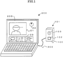
- FIG. 1 is a view showing an external configuration of an image photographing system in the first embodiment.
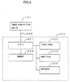
- FIG. 2 is a block diagram showing a hardware architecture of this image photographing system.
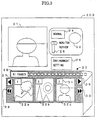
- FIG. 3 is a view showing a layout on a screen of a touch panel 203 provided in the image photographing system.
- FIG. 4 is a block diagram showing functions incorporated into a control program of the image photographing system 200.
- FIG. 5 is a view illustrating an image transition on the screen when in a new data adding process.
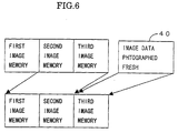
- FIG. 6 is a diagram showing an operation of an image memorywhen in the new data adding process.
- FIG. 7 is a view illustrating an image transition when in a display sequence changing process.
- FIG. 8 is a diagram showing an operation of the image memory when in the display sequence changing process.
- FIG. 9 is a diagram showing a structure of data handled by a display sequence management module 3 shown in FIG. 4.
- FIGS. 10 to 13 are flowcharts showing processes of the control program executed by a CPU
- FIG. 1 is the view illustrating the external configuration of the image photographing system in the first embodiment.
- the image photographing system is constructed of an image acquisition device 101 and a mobile terminal 200 that are connected to each other by a universal serial bus (which will hereinafter be abbreviated to USB) cable 300.
- USB universal serial bus
- the image acquisition device 101 includes a button 102 and a lens 103 for forming an image inside a body 100, which are provided on the front side of the body 100. Further, the image acquisition device 101 has an unillustrated CCD imaging device inwardly of the body 100.
- the lens 103 functions to form an image of an object on the CCD imaging device built in the image acquisition device body 100.
- the image formed on the CCD imaging device is read in real time by the mobile terminal 200 via the USB cable 300.
- the button 102 detects a depression by a user, and transmits it to the mobile terminal via the USB cable 300.
- FIG. 2 is the block diagram illustrating the hardware architecture of the image photographing system.
- the mobile terminal 200 includes a CPU 201 for reading digital image signals generated by the image acquisition device 101 via the USB cable 300 and thus controlling the photographing, a memory 202 for storing the control program executed by the CPU 201 and the data processed by the CPU 201, a touch panel 203 for displaying the data in accordance with an instruction given from the CPU 201 and detecting a user's operation, a hard disk 204 for recording the data, and a keyboard 206.
- the CPU 201 controls the photographing by executing the control program stored in the memory 202. To be more specific, the CPU 201 reads in real time the data of the image formed on the unillustrated CCD imaging device through the lens 103, and writes the image data to the memory 202. The image data written to the memory 202 are displayed on the touch panel 203.
- the CPU 201 monitors the button 102 on the basis of an interruption processing function. That is, when the user depresses the button 102 and then releases it, the CPU 201 detects this operation in accordance with an interruption processing program unillustrated. Upon detecting the depression and the release of the button 102, a photographing process is carried out.
- the memory 202 stores the program executed by the CPU 201 and the data processed by the CPU 201.
- the touch panel 203 is constructed of a combination of a liquid crystal display and a sensor for detecting a position where the user depresses. An image read from the CCD imaging device and icons for guiding the user's operation, are displayed on this touch panel
- What is well known as a sensor of the touch panel 203 may be a pressure sensitive type sensor, an electrostatic type sensor and an ultrasonic type sensor.
- the device for detecting the operating position of the user in terms of actualizing the present invention is not limited to the touch panel, and may be, as a matter of course, other devices such as a mouse, a keyboard, etc.
- the hard disk 204 records the data of the photographed image.
- FIG. 3 illustrates a layout on the screen of the touch panel 203.
- An image display area 21, a photographed button icon 22, a photographed image display frame area 23, a photographing mode menu 24, a display mode menu 25 and an environment setting menu 26, are displayed on a liquid crystal display of the touch panel 203.
- a display mode is changed by the display mode menu 25.
- the display mode is categorized into a monitor mode and a review mode.
- the latest image photographed by the image acquisition device 101 is displayed on the image display area 21. This image is read in real time to the mobile terminal 200 from the image acquisition device 101.
- the photographing button icon 22 serves to detect a photographing instruction of the user through the touch panel 203. The user instructs the photographing through the photographing button icon 22 or the button 102 provided on the image acquisition device 101.
- the photographed image display frame area 23 (corresponding to a second display area) includes, a film frame area simulating a configuration of a real film, three pieces of image display frames 32a, 32b, 32c segmented within this film frame area, a photograph count indicating portion 36 for indicating the number of images photographed, a leftward frame feed button 27 provided leftwards adjacent to the image display frame 32a provided at the left end, a leftward frame fast feed button 28 provided under the leftward frame feed button 27, a rightward frame feed button 29 provided rightwards adjacent to the image display frame 32c provided at the right end, and a rightward frame fast feed button 29 provided under the rightward frame feed button 29.
- the images displayed in the image display frames 32a, 32b, 32c are called frame images.
- the image display frames 32a, 32b, 32c provide a function of previewing each of the photographed images.
- a frame number (1 or 2 or 3 in FIG. 3) is provided at a left upper corner of each of the image display frames 32a, 32b, 32c.
- the leftward frame feed button 27 or the leftward frame fast feed button 28 the images in the image display frames 32a, 32b, 32c are fed in the left direction, and at the same time the frame number is sequentially incremented.
- the images in the image display frames 32a, 32b, 32c are fed in the right direction, and at the same time the frame number is sequentially decremented.
- calculations of the frame numbers involve the use of the number (51 pieces in FIG. 3) of images (managed at the present) obtained by the photographing, the position in the sequence of images, the number (3 pieces in FIG. 3) of images displayed at the present in the photographed image display frame area 23, and positions of the images displayed at the present in the photographed image display frame area 23. These items of data are retained on the memory 202. Then, corresponding to a new addition of the image obtained by the photographing process or to an insertion/transfer of the image by operating a variety of buttons, the frame number is calculated based on a position where the new frame image is inserted or a position to which the existing frame image is transferred.
- the number of the digital image data (the number of frames) stored at the present is displayed in the photograph count indicating portion 36.
- the photographing mode menu 24 is used for switching a photographing mode to a normal mode or a consecutive photographing mode.
- the display mode menu 25 is used for switching a mode of the image display area 21 to a monitor mode or a review mode.
- the environment setting menu 26 is used for setting an environment of the image photographing system, such as setting the number of consecutive photographs, a consecutive photographing interval, etc.
- FIG. 4 is the block diagram showing the functions of the control program executed by the CPU 201.
- This control program consists of a data display module 1 for displaying the data and images on the touch panel 203, a display data management module 2 for specifying the image data to be displayed by this data displaymodule 1, a display order management module 3 for managing a display order of the images to be displayed in the image display frames 32a, 32b, 32c, a file data acquiring module 4 for accessing to the recorded digital image data, a user operation recognizing module 5 for recognizing a user's operation, a photographing control module 6 for controlling the photographing in accordance with the user's operation, an image display module 7 for momentarily displaying the digital images generated by the CCD imaging device in the monitor mode and displaying the images photographed in the review mode, and a CCD reading module 8 for reading the digital image data from the CCD imaging device.
- a data display module 1 for displaying the data and images on the touch panel 203
- a display data management module 2 for specifying the
- the data display module 1 displays the frame image in the photographed image display frame area 23, a name of a file stored with the frame image, or file attributes (a photographing date, an inter-frame relation between the consecutive photographing and panorama photographing).
- the display data management module 2 indicates the data display module 1 to display which digital image data and which order this piece of digital image data is set, in the photographed image display frame area 23 (signal 15).
- the order herein is an order in which the digital photographed image data are arranged.
- the display order management module 3 manages an order of the digital photographed image data files.
- the file data acquiring module 4 stores in a file 9 the digital image data read by the CCD reading module 8 under the control of the photographing module 6.
- the file data acquiring module 4 and the CCD reading module 8 in combination correspond to an unit generating image data.
- the file data acquiring module 4 reads the digital image data and attributes of the same data from the file 9 (signal 17).
- the user operation recognizing module 5 recognizes which data is transferred and where, and which icon is depressed by the user's operation, e.g., drag-and-drop on the touch panel 203.
- the drag-and-drop herein connotes an operation of moving (dragging) an operation target displayed on the screen in a desired direction while pinpointing the operation target by pressing, and releasing (dropping) it in a desired position on the touch panel 203 by use of the mouse.
- the photographing control module 6 controls reading the data from the unillustrated CCD photographing device, and the display on the image display area 21.
- This photographing control module 6 and the data display module 1 in combination correspond to an unit displaying a screen.
- the photographing control module 6 momentarily reads the digital image data from the unillustrated CCD imaging device through the CCD reading module 8 (signal 18), and transfers the same data to the image display module 7 (signal 19).
- the image display module 7 momentarily displays the digital image data in the image display area 21 on the touch panel 203.
- the photographing control module 6 when receiving a photographing instruction (signal 21) from the user operation recognizing module 5 (corresponding to an unit detecting a photographing instruction), transfers to the file data acquiring module 4 the digital image data read from the CCD imaging device (signal 22). As a result, the digital image data are stored as a file in the hard disk 204.
- a name of the stored file is transferred to the display data management module 2 (signal 14).
- the display data management module 2 sends, to the display order management module 3, the order of the digital image data that is displayed in the image display frame 32c provided at the right end on the touch panel 203 and the file name of the digital image data stored fresh (signal 11).
- the file name of the digital image data stored fresh there is registered of the file name of the digital image data stored fresh next to the order corresponding to the image display frame 32c provide at the right end at the present.
- the display data management module 2 shifts the order by one frame, in which the images should be displayed in the photographed image display frame area 23, and notifies the data display module 1 of this new order (signal 15).
- the frame -images in the photographed image display frame area 23 are thereby shifted leftward frame by frame, and a frame image of the digital image data stored fresh is displayed in the tail frame (in a position corresponding to the right-end image display frame 32c).
- the photographing control module 6 reads the digital image data corresponding to a specified-by-the-user frame image in the photographed image display frame area 23 through the file data acquiring module 4, and transfers the same data to the image display module 7.
- the frame image specified by the user is enlarged and displayed in the image display area 21 on the touch panel 203.
- the process of setting the digital image data of the newly photographed image under the management of the display order management module 3 and displaying the digital image data in the image display frame 32c in the way described above, is termed a new data adding process.
- FIG. 5 shows an image transition on the screen when in the new data adding process.
- the photograph count indicating portion 36 in a photographed image display frame area 23a indicates that the number of photographs is 51 at the present. Further, three top images (with the frame numbers 1, 2 and 3) among the 51 pieces of images are displayed in the photographed image display frame area 23a.
- the data of the unillustrated CCD imaging device are given a predetermined file name and stored in the hard disk 204.
- the images displayed in the photographed image display frame area 23a are shifted frame by frame and thus rearranged as displayed in a photographed image display frame area 23b. Namely, the image with the frame number 1 is shifted leftward with no display. Further, the image with the frame number 2 is shifted to the left-end position (corresponding to the image display frame 32a) . Moreover, the image with the frame number 3 is shifted to the central position (corresponding to the image display frame 32b) . Furthermore, an image with the frame number 4 which is photographed just now is inserted in the right-end position (corresponding to the image display frame 32c).
- FIG. 6 shows the memory operation when in the new data adding process.
- the frame images in the three frames in the photographed image display frame area 23 are retained in first through third image memories.
- the CPU 201 at first copies the data in the second image memory to the first image memory.
- the CPU 201 copies the data in the third image memory to the second image memory.
- the CPU 201 copies image data 40 of a newly photographed image to the third image memory.
- FIG. 7 illustrates the image transition on the screen when in the display order changing process.
- three top images (with the frame numbers 1, 2 and 3) among the 51 pieces of images are displayed in the photographed image display frame area 23a.
- FIG. 8 shows the memory operation when in the display order changing process.
- three pieces of frame images before executing the display order changing process are retained in the first through third memories.
- the CPU 201 copies the data in the first image memory to a temporary saving memory 41.
- the CPU 201 copies the data in the third image memory to the first memory.
- the CPU 201 copies the data in the second image memory to the third memory.
- the CPU 201 copies the data in the temporary saving memory 41 to the second memory.
- This memory operation enables the image transition on the screen shown in FIG. 7 to be actualized.
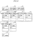
- FIG. 9 shows a data structure managed by the display order management module 3.
- This data structure is generally known as a list structure.
- the list structure represents an order relation between a plurality of data elements linked by next addresses 54a, 54b, 54c and so on.
- a data element of which a next address 54f is NULL is the tail data element.
- Each data element based on this data structure retains a file name, a date, etc in addition to the next address (54a, etc).
- the file name is a name of a file for storing the digital image data.
- the date is a photographing date when the digital image data are created.
- the head data element is indicated by a list head address 50. Further, the tail data element is indicated by a list tail address 51.
- the data elements corresponding to the digital image data displayed in the photographed image display frame area 23, are indicated by an intra-screen head address 52 and an intra-screen tail address 53.
- the display order management module 3 when given an instruction to add a new piece of data or change the display order, changes the display order of the files that store the digital image data by operating the data structure illustrated in FIG. 9.
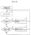
- FIGS. 10 through 13 show the processes (recognition of operation for photographing process and the order changing process) of the control program executed by the CPU 201 of the mobile terminal 200.
- the CPU 201 provides a function as the image photographing system by executing the control program.
- the CPU 201 In the normal state, the CPU 201 is in a wait-for-event state (S1). In terminology, the "event” implies a factor for making a control state of the CPU 201 be changed. When the event occurs, the CPU 201 judges a category of this event.
- the photographing event is a photographing instruction given by the user.
- the photographing event occurs when the user depresses the button 102 of the image acquisition device 101 or depresses the photographing button 22 on the touch panel 203. That is, upon depressing the button 102 etc, the CPU 201 executes an interrupting process , and a detection of depression on the button is transmitted to the CPU 201.
- the CPU 201 executes the photographing process (S3).
- the CPU 201 judges whether or not the event concerned is a display order change event (S4). If the user instructs a change in the display order in the photographed image display frame area 23 on the touch panel 203, this display order change event occurs.
- the CPU 201 executes a display order changing process (S5). If not the display order change event, the CPU 201 executes nothing and reverts to the wait-for-event state (S1).
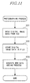
- FIG. 11 shows the photographing process (S3 in FIG. 10) executed by the CPU 201.
- the CPU 201 reads the digital image data from the CCD imaging device (S31).
- the CPU 201 stores the digital image data given a predetermined file name in the hard disk 204 (S32).
- the CPU 201 executes a new data adding process in order to add the file name stored therein to the list structure shown in FIG. 9 (S33).
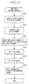
- FIG. 12 shows the new data adding process (S33 in FIG. 11).
- the file name of the digital image data of the photographed image is registered in the list structure managed by the display order management module 3.
- the CPU 201 obtains from the list structure the data element corresponding to the frame image positioned rightward most (which is displayed in the image display frame 32c) among the frame images displayed on the touch panel 203 (S331). This data element can be also obtained from the intra-screen tail address 53 in FIG. 9. This data element is called an intra-screen tail data element.
- the CPU 201 ensures a region for a new data element on the memory 202, and generates the new data element (S332).
- the CPU 201 inserts the new data element in a position next to the intra-screen tail data element, and rewrites a next address held by the intra-screen tail data element so that the order of the data element matches to this arrangement, and sets a next address held by the new data element (S333).
- the CPU 201 sets a name of the file stored with the digital image data in the process in S32 (S334). Furthermore, attributes such as the photographing date etc are set in this new data element (S335).
- next address indicated by the data element corresponding to the image positioned in the image display frame 32c before the photographing process is rewritten into the address of the data element added in the photographing process. Further, the next address indicated by the data element with respect to the new image added, is set to the address of the data element of the image arranged in the display order next to the image positioned in the image display frame 32c.
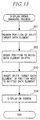
- FIG. 13 shows the display order changing process (S5 in FIG. 10).
- the CPU 201 searches a position of a shift target data element (S51). This position is determined from a drag target frame image on the touch panel 203.
- the CPU 201 searches a position to which the data element shifts (S52). This position is determined from a drop position on the touch panel 203.
- the CPU 201 moves the data element corresponding to the drag target frame image, to the position to which the data element is inserted (S53). This is because the next address 54a etc held by the data elements in the list structure are rewritten. The order of the data elements is thereby changed.
- the CPU 201 executes the memory operation shown in FIG. 8, and the frame images after the display order changing process are displayed (S54).
- the image photographing system in the first embodiment is constructed so that the photographing target image and the image data (still image) generated from the image by the photographing process, are displayed on the same screen, thereby eliminating the necessity of switching between the photographing process and the browsing of the photographed image data. This enhances a usability.
- the frames in the photographed image display frame area 23 are shifted, and the photographed image is displayed in the tail frame therein. Accordingly, the user is able to confirm the photographed result without effecting again the switchover to a thumbnail screen.
- the frame images in the photographed image display frame area 23 simulated to the real film are shifted, and thereafter the frame image photographed fresh is added. Therefore, the user is able to really sense the photographing itself.
- the newly added image is inserted as the last frame image among those displayed at the present on the touch panel 203. Therefore, even in the case of managing the multiplicity of images enough not to be displayed on one screen, the newly added image can be confirmed.
- the desired piece of image data can be easily shifted based on the desired display order by the drag & drop.
- the frame images are shifted in the left direction in the photographed image display frame area 23 when in the new data adding process, and the newly photographed image is displayed in the image display frame 32c provided at the right end thereof.
- the present invention is not, however, limited to this mode.
- the newly photographed image may be inserted in the position of a central image display frame area 32b, and the existing frame images displayed in the image display frame area 32b may be shifted in either the right direction or the left direction.
- the newly photographed image may be displayed in the image display frame 32a at the left end by shifting rightward the existing frame images displayed in the image display frames 32a, 32b.
- the data elements in the list structure may be added and rewritten so that the image data as a basis of the frame image displayed in the image display frame 32c at the right end is arranged next to the newly photographed image by displaying the newly photographed image in the image display frame 32c at the right end.
- next address held by the related data element in the list structure may be set by updating in accordance with the insert position of the newly photographed image and with the direction in which existing frame images are thereby shifted.
- the number of the frame images in the photographed image display frame area 23 may not necessarily be 3 and may be an arbitrary number of 1 or greater.
- the number of frame images displayable in the photographed image display frame area 23 may be determined based on a size and a resolution of the display, a display space possible of being taken as the photographed image display frame area 23, and a size of the image data obtained by the photographing. Note that it is preferable in terms of grasping the display order (arranging order) of the already-photographed images to display two or more frame images .
- the image photographing system is constructed by connecting the image acquisition device 101 and the mobile terminal 200 to each other via the USB cable 300.
- the embodiment of the present invention is not, however, limited to this architecture.
- the on-screen elements such as the image display area 21, the photographed image display frame area 23, etc
- the control program described in this embodiment may also be executed by use of a personal computer or a cellular phone as a substitute for the mobile terminal 200.
- the image acquisition device 101 may be connected to the mobile terminal 200 by use of other types of cables such as an optical fiber. Further, the image acquisition device 101 may be connected to the mobile terminal 200 by use of wireless communication devices, for example, an infrared-ray emitting unit and a light receiving unit, or a transmitter and a receiver in a radio frequency region.
- wireless communication devices for example, an infrared-ray emitting unit and a light receiving unit, or a transmitter and a receiver in a radio frequency region.
- Each of the USB cable 300, the connecting terminal such as the optical fiber, the light receiving unit or the receiver corresponds to an unit for inputting from an outside device.
- the image acquisition device 101 provided with the CCD imaging device is used in the embodiment discussed above.
- the embodiment of the present invention is not, however, confined to this configuration.
- a MOS image sensor may be used in place of the CCD imaging device.
- the image photographing system in the embodiment discussed above involves the use of the hard disk 204 as a recording unit.
- the embodiment of the present invention is not, however, restricted to this configuration.
- a variety of readable-by-computer recording mediums, e.g., a memory card using a flash memory may be usable as the recording unit.
- the image acquisition device 101 provided with the CCD imaging device for forming the image to be displayed in the image display area 21, is exemplified in the discussion on the embodiment discussed above.
- the present invention is not, however, limited to this image acquisition device 101.
- a picture obtained by TV broadcasting, satellite broadcasting and wireless broadcasting, a picture obtained by wired broadcasting such as on a cable TV, a picture reproduced by a video deck, and picture data transmitted by utilizing a network such as the Internet, may also be displayed in the image display area 21.
- a receiving device corresponding to an outside device
- a picture delivery mode may be used in order to receive the picture from outside.
- the picture displayed in the picture display area 21 may be CG animation obtained from a reproduced result and calculating process of the picture data stored in a storage device, e.g., the memory 202 and the hard disk 204 in FIG. 2, provided in the system for executing the processing function of the present invention.
- a storage device e.g., the memory 202 and the hard disk 204 in FIG. 2, provided in the system for executing the processing function of the present invention.
- the present invention is not restricted to what obtains the picture from outside the system incorporating the processing function of the present invention, and the picture generated and reproduced by the self-system may also be displayed in the picture display area 21.
- the control program in the first embodiment can be recorded on a readable-by-computer recording medium. Then, a computer reads and executes the control program on this recording medium, whereby the computer can function as the image photographing system demonstrated in the first embodiment.
- the readable-by-computer recording medium embraces recording mediums capable of storing information such as data, programs, etc. electrically, magnetically, optically and mechanically or by chemical action, which can be all read by the computer. What is demountable out of the computer among those recording mediums may be, e.g., a floppy disk, a magneto-optic disk, a CD-ROM, a CD-R/W, a DVD, a DAT, an 8mm tape, a memory card, etc.
- a hard disk a ROM (Read Only Memory) and so on are classified as fixed type recording mediums within the computer.
- control program may be stored in the hard disk and the memory of the computer, and downloaded to other computers via communication media.
- the program is transmitted as data communication signals embodied in carrier waves via the communication media.
- the computer downloaded with this program can be made to function as the image photographing system explained in this embodiment.
- the communication media may be any one of wired communication mediums (such as metallic cables including a coaxial cable and a twisted pair cable, or an optical communication cable), and wireless communication media (such as satellite communications, ground wave wireless communications, etc.).
- wired communication mediums such as metallic cables including a coaxial cable and a twisted pair cable, or an optical communication cable
- wireless communication media such as satellite communications, ground wave wireless communications, etc.
- the carrier waves are electromagnetic waves for modulating the data communication signals, or the light.
- the carrier waves may, however, be DC signals (in this case, the data communication signals take a base band waveform with no carrier wave).
- the data communication signal embodied in the carrier wave may be any one of amodulated broadband signal and an unmodulated base band signal (corresponding to a case where the DC signal having a voltage of 0 is set as a carrier wave).
- FIGS. 14 to 18 A second embodiment of the present invention will be described with reference to FIGS. 14 to 18.
- the first embodiment discussed above has dealt with the image photographing system for creating the digital image data of the object in accordance with the photographing instruction of the user in the mobile terminal provided with the image acquisition device 101. And it has dealt with the on-screen display when managing the file stored with the digital image data, too.
- a data processing device corresponding to the data management device for managing a general data file.
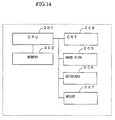
- FIG. 14 is a block diagram showing a hardware architecture of the data processing device.
- FIG. 15 is a diagram showing an on-screen architecture of a file management program executed by the data processing device.
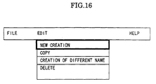
- FIG. 16 is a diagram showing an edit menu of the file management program.
- FIG. 17 is a flowchart showing a new creating process of the file management program.
- FIG. 14 is the block diagram illustrating the hardware architecture of the data processing device in the second embodiment.
- the data processing device has, as compared with the mobile terminal in the first embodiment, a difference in terms of having a CRT 208 and a mouse 207. Further, the data processing device does includes neither the image acquisition device 101 nor the touch panel 203. Other components are the same as those in the first embodiment. The same components in the second embodiment as those in the first embodiment are marked with the same numerals, of which the repetitive explanations are omitted. Further, the drawings in FIGS. 1 to 13 will be used for reference as the necessity may arise.
- Output data from the CPU and input data from the keyboard 206 are displayed on the CRT 208.
- the keyboard 206 and the mouse 207 are used when the user inputs characters and performs a menu operation.
- FIG. 15 illustrates the on-screen architecture displayed on the CRT 208 when the CPU 201 of the data processing device executes the file management program.
- the files managed by the file management program are designated at 3-tiered levels of unit, directory and file.
- the data management device is capable of managing a plurality of units, a plurality of directories and a plurality of files.
- the directory may be hierarchically defined under other directories. Note that the unit embraces a physical drive and a logical drive.
- FIG. 15 an unit A and a directory A framed with bold lines are now set as operation targets. Accordingly, referring again to FIG. 15, there are displayed files A, B and C that are defined by the directory A within the unit A. Other files D, E exist in the directory A but are invisible under the screen.
- FIG. 16 shows an edit menu of this file management program.
- the edit menu is provided with items such as new creation, copy, creation of different name, and delete.
- New creation indicates that a new file is created in the directory set as the operation target at the present. The file with a null content is thereby created.
- Copy implies that the existing file is copied, and a new file is created.
- FIG. 17 shows a result of executing "new creation" in the display state shown in FIG. 15.
- a newly added file is inserted in a tail of the file list displayed on the screen.
- the file A when the new file is added to the file list shown inFIG. 15, the file A, as illustrated in FIG. 17, becomes invisible above the screen. Then, the file B is displayed in the position of the file A, and the file C is displayed in the position of the file B. Thus, the newly created file is displayed at the lower end on the screen.
- the file management conducted in this way can be, as in the first embodiment, actualized based on the list structure illustrated in FIG. 9.
- FIG. 18 shows a new creation process.
- the CPU 201 when detecting a menu operation (selection of "new creation") of the user, boots this new creation process.
- the CPU 201 obtains from the list structure the file existing at the lower end on the screen among the files displayed (S61). This data element can be obtained from the intra-screen tail address 53 in FIG. 9.
- the CPU 201 ensures a region for a new data element on the memory 202, and generates the new data element (S62).
- the CPU 201 inserts this new data element next to the intra-screen tail data element obtained above (S63).
- the CPU 201 requests the user to input a naive of the new file. Then, the CPU 201 sets the inputted file name in the new data element (S64). Further, attributes such as a data of create etc are set in this new data element (S65).
- the intra-screen head address 52 and the intra-screen tail address 53 in FIG. 9 are advanced element by element, and a result of this is displayed on the screen (S66).
- the display in FIG. 15 is thereby changed to the display in FIG. 17.
- this file (or a different name of the file) is inserted in the position displayed on the screen, and hence the result of adding the management target can be easily confirmed.
- the files displayed are shifted file by file in the upper direction on the screen when in the new addition process (with, e.g., the fileAconcealed) , and the newly created file is added at the lower end on the screen.
- the embodiment of the present invention is not, however, limited to this processing mode.
- the shifting direction may be set opposite (downward on the screen) to the direction in FIG. 17).
- the newly created file may be inserted in any one of the positions of the files A, B and C.
Landscapes
- Engineering & Computer Science (AREA)
- Multimedia (AREA)
- Signal Processing (AREA)
- Human Computer Interaction (AREA)
- Studio Devices (AREA)
- Television Signal Processing For Recording (AREA)
- Measuring And Recording Apparatus For Diagnosis (AREA)
Applications Claiming Priority (2)
| Application Number | Priority Date | Filing Date | Title |
|---|---|---|---|
| JP2000043661 | 2000-02-21 | ||
| JP2000043661 | 2000-02-21 |
Publications (2)
| Publication Number | Publication Date |
|---|---|
| EP1128656A2 true EP1128656A2 (de) | 2001-08-29 |
| EP1128656A3 EP1128656A3 (de) | 2002-01-09 |
Family
ID=18566541
Family Applications (1)
| Application Number | Title | Priority Date | Filing Date |
|---|---|---|---|
| EP01301493A Withdrawn EP1128656A3 (de) | 2000-02-21 | 2001-02-20 | Bildaufnahmesystem mit Datenverwaltungsfunktion, Datenverwaltungsverfahren und Speichermedium |
Country Status (2)
| Country | Link |
|---|---|
| US (1) | US7474348B2 (de) |
| EP (1) | EP1128656A3 (de) |
Cited By (3)
| Publication number | Priority date | Publication date | Assignee | Title |
|---|---|---|---|---|
| EP2045703A3 (de) * | 2007-10-04 | 2010-09-08 | LG Electronics Inc. | Mobiles Endgerät und Bildanzeigeverfahren dafür |
| CN106228511A (zh) * | 2015-06-02 | 2016-12-14 | 三星电子株式会社 | 电子装置以及用于在电子装置中产生图像文件的方法 |
| RU2836210C1 (ru) * | 2024-07-25 | 2025-03-11 | Федеральное государственное бюджетное образовательное учреждение высшего образования "Уральский государственный медицинский университет" Министерства здравоохранения Российской Федерации (ФГБОУ ВО УГМУ Минздрава России) | Способ проведения фотосъемки перед омолаживающей операцией на лице и в послеоперационном периоде |
Families Citing this family (25)
| Publication number | Priority date | Publication date | Assignee | Title |
|---|---|---|---|---|
| JP3631176B2 (ja) * | 2001-08-01 | 2005-03-23 | キヤノン株式会社 | 撮像装置、及び、撮像装置における画像データの付属情報の修正方法 |
| US20050081138A1 (en) * | 2003-09-25 | 2005-04-14 | Voss James S. | Systems and methods for associating an image with a video file in which the image is embedded |
| US20050190280A1 (en) * | 2004-02-27 | 2005-09-01 | Haas William R. | Method and apparatus for a digital camera scrolling slideshow |
| JP2005309995A (ja) * | 2004-04-23 | 2005-11-04 | Olympus Corp | 情報管理装置、情報管理方法、及びプログラム |
| US7714926B2 (en) | 2004-05-13 | 2010-05-11 | Sony Corporation | Imaging apparatus, user interface, and associated methodology for a co-existent shooting and reproduction mode |
| JP2006042171A (ja) * | 2004-07-29 | 2006-02-09 | Olympus Corp | カメラ、再生装置およびアルバム登録方法 |
| JP2006311366A (ja) * | 2005-04-28 | 2006-11-09 | Matsushita Electric Ind Co Ltd | 画像記録装置及び画像記録装置の駆動方法 |
| JP4525458B2 (ja) * | 2005-05-09 | 2010-08-18 | 船井電機株式会社 | ハードディスクレコーダ |
| KR101155526B1 (ko) * | 2005-06-15 | 2012-06-19 | 삼성전자주식회사 | 찾아가기 기능을 가진 디지털 영상 처리 장치의 제어 방법 |
| JP4792985B2 (ja) * | 2006-01-18 | 2011-10-12 | カシオ計算機株式会社 | カメラ装置、撮影条件設定方法、及び、プログラム |
| JP4732370B2 (ja) * | 2006-02-13 | 2011-07-27 | キヤノン株式会社 | デジタルカメラ、その制御方法、プログラム |
| US20070204238A1 (en) * | 2006-02-27 | 2007-08-30 | Microsoft Corporation | Smart Video Presentation |
| US8672752B2 (en) * | 2007-11-09 | 2014-03-18 | Wms Gaming, Inc. | Interface for wagering game environments |
| KR20100013705A (ko) * | 2008-07-31 | 2010-02-10 | 삼성디지털이미징 주식회사 | 디지털 영상 처리 장치, 그 제어 방법 및 이를 실행시키기위한 프로그램을 저장한 기록 매체 |
| KR101436841B1 (ko) * | 2008-08-19 | 2014-09-03 | 삼성전자주식회사 | 디지털 이미지 처리장치 |
| JP4656218B2 (ja) * | 2008-09-10 | 2011-03-23 | カシオ計算機株式会社 | 画像表示装置、及び画像表示方法、画像表示プログラム |
| US8134539B2 (en) * | 2009-03-30 | 2012-03-13 | Eastman Kodak Company | Digital picture frame having near-touch and true-touch |
| WO2011097405A1 (en) * | 2010-02-03 | 2011-08-11 | Nik Software, Inc. | Narrative-based media organizing system for converting digital media into personal story |
| JP2011244367A (ja) * | 2010-05-21 | 2011-12-01 | Hitachi Consumer Electronics Co Ltd | 記録方法 |
| US20130080932A1 (en) * | 2011-09-27 | 2013-03-28 | Sanjiv Sirpal | Secondary single screen mode activation through user interface toggle |
| KR20130069039A (ko) * | 2011-12-16 | 2013-06-26 | 삼성전자주식회사 | 디스플레이 장치, 방법, 및 컴퓨터 판독 가능 저장 매체 |
| TWI486794B (zh) * | 2012-07-27 | 2015-06-01 | Wistron Corp | 影片預覽方法及系統及其電腦程式產品 |
| US20140298246A1 (en) * | 2013-03-29 | 2014-10-02 | Lenovo (Singapore) Pte, Ltd. | Automatic display partitioning based on user number and orientation |
| JP6321959B2 (ja) * | 2013-12-25 | 2018-05-09 | キヤノン株式会社 | 表示制御装置、表示制御方法、及び、プログラム |
| KR20170131101A (ko) * | 2016-05-20 | 2017-11-29 | 엘지전자 주식회사 | 이동 단말기 및 그 제어방법 |
Citations (5)
| Publication number | Priority date | Publication date | Assignee | Title |
|---|---|---|---|---|
| US5161025A (en) | 1989-12-28 | 1992-11-03 | Fuji Photo Film Co., Ltd. | Optical/electrical view finder |
| JPH10285520A (ja) | 1998-02-18 | 1998-10-23 | Matsushita Electric Ind Co Ltd | 記録再生装置 |
| JPH11168694A (ja) * | 1997-06-27 | 1999-06-22 | Eastman Kodak Co | 電子スチルカメラ |
| US5933137A (en) | 1997-06-10 | 1999-08-03 | Flashpoint Technology, Inc. | Method and system for acclerating a user interface of an image capture unit during play mode |
| US5943050A (en) | 1994-04-07 | 1999-08-24 | International Business Machines Corporation | Digital image capture control |
Family Cites Families (37)
| Publication number | Priority date | Publication date | Assignee | Title |
|---|---|---|---|---|
| US4827347A (en) * | 1988-08-22 | 1989-05-02 | Eastman Kodak Company | Electronic camera with proofing feature |
| US5339393A (en) | 1993-04-15 | 1994-08-16 | Sony Electronics, Inc. | Graphical user interface for displaying available source material for editing |
| US6359649B1 (en) * | 1995-04-04 | 2002-03-19 | Canon Kabushiki Kaisa | Video camera integrated with still camera |
| JP3672970B2 (ja) | 1995-05-22 | 2005-07-20 | 株式会社ミツトヨ | 非接触画像計測システム |
| JP3562049B2 (ja) * | 1995-07-21 | 2004-09-08 | セイコーエプソン株式会社 | 映像表示方法および装置 |
| JPH09297750A (ja) | 1996-03-08 | 1997-11-18 | Nikon Corp | ソースファイル編集装置 |
| US5966122A (en) * | 1996-03-08 | 1999-10-12 | Nikon Corporation | Electronic camera |
| JPH09294226A (ja) | 1996-04-26 | 1997-11-11 | Eiji Watanabe | 電子アルバム高速作成システム |
| US5859623A (en) * | 1996-05-14 | 1999-01-12 | Proxima Corporation | Intelligent display system presentation projection arrangement and method of using same |
| US6249316B1 (en) * | 1996-08-23 | 2001-06-19 | Flashpoint Technology, Inc. | Method and system for creating a temporary group of images on a digital camera |
| JPH10126796A (ja) * | 1996-09-12 | 1998-05-15 | Eastman Kodak Co | デュアル・モード・ソフトウェア処理を用いた動画・静止画像用デジタル・カメラ |
| US6147703A (en) * | 1996-12-19 | 2000-11-14 | Eastman Kodak Company | Electronic camera with image review |
| US6340971B1 (en) * | 1997-02-03 | 2002-01-22 | U.S. Philips Corporation | Method and device for keyframe-based video displaying using a video cursor frame in a multikeyframe screen |
| US5978016A (en) * | 1997-02-20 | 1999-11-02 | Eastman Kodak Company | Electronic camera with internal fixed album memory |
| JPH10243273A (ja) * | 1997-02-24 | 1998-09-11 | Canon Inc | デジタルカメラ用画像表示方法 |
| US5973691A (en) * | 1997-04-30 | 1999-10-26 | Sony Corporation | Display of multiple images based on a temporal relationship among them with various operations available to a user as a function of each displayed image size |
| US6310648B1 (en) * | 1997-09-12 | 2001-10-30 | Eastman Kodak Company | User interface for electronic image viewing apparatus |
| US6028603A (en) * | 1997-10-24 | 2000-02-22 | Pictra, Inc. | Methods and apparatuses for presenting a collection of digital media in a media container |
| US5923908A (en) * | 1997-10-30 | 1999-07-13 | Eastman Kodak Company | Camera with touch sensitive control |
| JPH11232440A (ja) * | 1998-02-18 | 1999-08-27 | Casio Comput Co Ltd | 画像処理装置 |
| JPH11308488A (ja) * | 1998-04-17 | 1999-11-05 | Canon Inc | ビデオカメラ、ビデオカメラシステム、撮影方法、ビデオ信号処理方法及び記憶媒体 |
| JPH11327721A (ja) | 1998-05-20 | 1999-11-30 | Canon Inc | 画像編集装置及び方法並びに記憶媒体 |
| US6538698B1 (en) * | 1998-08-28 | 2003-03-25 | Flashpoint Technology, Inc. | Method and system for sorting images in an image capture unit to ease browsing access |
| US6453078B2 (en) * | 1998-08-28 | 2002-09-17 | Eastman Kodak Company | Selecting, arranging, and printing digital images from thumbnail images |
| JP4240186B2 (ja) * | 1998-09-17 | 2009-03-18 | ソニー株式会社 | 画像表示装置および方法 |
| US6734909B1 (en) * | 1998-10-27 | 2004-05-11 | Olympus Corporation | Electronic imaging device |
| US6738075B1 (en) * | 1998-12-31 | 2004-05-18 | Flashpoint Technology, Inc. | Method and apparatus for creating an interactive slide show in a digital imaging device |
| US6317141B1 (en) * | 1998-12-31 | 2001-11-13 | Flashpoint Technology, Inc. | Method and apparatus for editing heterogeneous media objects in a digital imaging device |
| US7016059B1 (en) * | 1999-08-31 | 2006-03-21 | Shutterfly, Inc. | Printing images in an optimized manner |
| US7152210B1 (en) * | 1999-10-20 | 2006-12-19 | Koninklijke Philips Electronics N.V. | Device and method of browsing an image collection |
| JP4325075B2 (ja) * | 2000-04-21 | 2009-09-02 | ソニー株式会社 | データオブジェクト管理装置 |
| AU2001283538A1 (en) * | 2000-08-04 | 2002-02-18 | Tom C. Hill | Method and system for presenting digital media |
| JP4122693B2 (ja) * | 2000-08-09 | 2008-07-23 | 株式会社ニコン | 電子カメラ |
| JP3914705B2 (ja) * | 2000-11-29 | 2007-05-16 | 富士フイルム株式会社 | ディジタル・カメラおよびその動作制御方法 |
| US7304677B2 (en) * | 2000-12-13 | 2007-12-04 | Eastman Kodak Company | Customizing a digital camera based on demographic factors |
| US7050097B2 (en) * | 2001-11-13 | 2006-05-23 | Microsoft Corporation | Method and apparatus for the display of still images from image files |
| KR101058019B1 (ko) * | 2004-11-10 | 2011-08-19 | 삼성전자주식회사 | 통합 디스플레이 모드가 수행되는 디지털 촬영 장치의제어 방법, 및 이 방법을 채용한 디지털 촬영 장치 |
-
2001
- 2001-02-20 EP EP01301493A patent/EP1128656A3/de not_active Withdrawn
- 2001-02-21 US US09/788,387 patent/US7474348B2/en not_active Expired - Fee Related
Patent Citations (6)
| Publication number | Priority date | Publication date | Assignee | Title |
|---|---|---|---|---|
| US5161025A (en) | 1989-12-28 | 1992-11-03 | Fuji Photo Film Co., Ltd. | Optical/electrical view finder |
| US5943050A (en) | 1994-04-07 | 1999-08-24 | International Business Machines Corporation | Digital image capture control |
| US5933137A (en) | 1997-06-10 | 1999-08-03 | Flashpoint Technology, Inc. | Method and system for acclerating a user interface of an image capture unit during play mode |
| JPH11168694A (ja) * | 1997-06-27 | 1999-06-22 | Eastman Kodak Co | 電子スチルカメラ |
| US6233015B1 (en) * | 1997-06-27 | 2001-05-15 | Eastman Kodak Company | Camera with user compliant browse and display modes |
| JPH10285520A (ja) | 1998-02-18 | 1998-10-23 | Matsushita Electric Ind Co Ltd | 記録再生装置 |
Cited By (6)
| Publication number | Priority date | Publication date | Assignee | Title |
|---|---|---|---|---|
| EP2045703A3 (de) * | 2007-10-04 | 2010-09-08 | LG Electronics Inc. | Mobiles Endgerät und Bildanzeigeverfahren dafür |
| US8606326B2 (en) | 2007-10-04 | 2013-12-10 | Lg Electronics Inc. | Mobile terminal and image display method thereof |
| CN106228511A (zh) * | 2015-06-02 | 2016-12-14 | 三星电子株式会社 | 电子装置以及用于在电子装置中产生图像文件的方法 |
| US10510170B2 (en) | 2015-06-02 | 2019-12-17 | Samsung Electronics Co., Ltd. | Electronic device and method for generating image file in electronic device |
| CN106228511B (zh) * | 2015-06-02 | 2020-02-28 | 三星电子株式会社 | 电子装置以及用于在电子装置中产生图像文件的方法 |
| RU2836210C1 (ru) * | 2024-07-25 | 2025-03-11 | Федеральное государственное бюджетное образовательное учреждение высшего образования "Уральский государственный медицинский университет" Министерства здравоохранения Российской Федерации (ФГБОУ ВО УГМУ Минздрава России) | Способ проведения фотосъемки перед омолаживающей операцией на лице и в послеоперационном периоде |
Also Published As
| Publication number | Publication date |
|---|---|
| EP1128656A3 (de) | 2002-01-09 |
| US7474348B2 (en) | 2009-01-06 |
| US20010015762A1 (en) | 2001-08-23 |
Similar Documents
| Publication | Publication Date | Title |
|---|---|---|
| US7474348B2 (en) | Image photographing system having data management function, data management device and medium | |
| JP4453738B2 (ja) | ファイル転送方法、装置、およびプログラム | |
| US8250490B2 (en) | Display image control apparatus | |
| US8214739B2 (en) | Imaging device and user interface | |
| EP2315111B1 (de) | Verfahren und Vorrichtung zum Durchsuchen von Medieninhalt und Ausführungsfunktionen im Zusammenhang mit dem Medieninhalt | |
| RU2437169C2 (ru) | Устройство отображения изображения, устройство съемки изображения | |
| US6154218A (en) | Method for generating, managing and displaying information retrieval data on information processing system | |
| US20030011683A1 (en) | Digital camera | |
| US20050226530A1 (en) | Image processing program, image processing method, image processing apparatus and storage medium | |
| EP1975917A2 (de) | Verfahren und System zur Wiedergabe von Inhalten sowie Aufzeichnungsmedium mit Programm zur Inhaltswiedergabe | |
| US6972774B2 (en) | Image processing system for inserting plurality of images into composite area, and medium | |
| CN112416485A (zh) | 信息引导方法、装置、终端及存储介质 | |
| JPH11328209A (ja) | 画像検索装置及び方法 | |
| JP4338210B2 (ja) | 画像管理装置及び画像管理方法、プログラム | |
| US20040263662A1 (en) | Image-processing apparatus, image-taking apparatus, and image-processing program | |
| CN102473441A (zh) | 突出略图中的差别的系统、包括该系统的移动电话及方法 | |
| US9646647B2 (en) | Content management apparatus, recording apparatus, operation apparatus, content management system, and control methods thereof | |
| US20090109199A1 (en) | Display control apparatus, display control method and program | |
| CN1812531B (zh) | 图像处理装置及其控制方法 | |
| CN115268754A (zh) | 显示终端的控制方法、系统、显示设备以及存储介质 | |
| US6947926B2 (en) | Data processing method and apparatus and storage medium | |
| US20070025197A1 (en) | Information-processing apparatus, recording medium and information-processing method | |
| US20050102609A1 (en) | Image processing apparatus, image processing method, and image processing program | |
| JP2001313861A (ja) | 画像撮影装置、データ管理装置、媒体、およびプログラム | |
| JP4458785B2 (ja) | 画像管理装置 |
Legal Events
| Date | Code | Title | Description |
|---|---|---|---|
| PUAI | Public reference made under article 153(3) epc to a published international application that has entered the european phase |
Free format text: ORIGINAL CODE: 0009012 |
|
| AK | Designated contracting states |
Kind code of ref document: A2 Designated state(s): AT BE CH CY DE DK ES FI FR GB GR IE IT LI LU MC NL PT SE TR Kind code of ref document: A2 Designated state(s): DE GB |
|
| AX | Request for extension of the european patent |
Free format text: AL;LT;LV;MK;RO;SI |
|
| RIC1 | Information provided on ipc code assigned before grant |
Free format text: 7H 04N 5/232 A |
|
| PUAL | Search report despatched |
Free format text: ORIGINAL CODE: 0009013 |
|
| AK | Designated contracting states |
Kind code of ref document: A3 Designated state(s): AT BE CH CY DE DK ES FI FR GB GR IE IT LI LU MC NL PT SE TR |
|
| AX | Request for extension of the european patent |
Free format text: AL;LT;LV;MK;RO;SI |
|
| 17P | Request for examination filed |
Effective date: 20020617 |
|
| AKX | Designation fees paid |
Free format text: DE GB |
|
| STAA | Information on the status of an ep patent application or granted ep patent |
Free format text: STATUS: THE APPLICATION IS DEEMED TO BE WITHDRAWN |
|
| 18D | Application deemed to be withdrawn |
Effective date: 20111105 |