EP1129622B1 - Verfahren und Vorrichtung zur Reinigung von Muschelschalen - Google Patents
Verfahren und Vorrichtung zur Reinigung von Muschelschalen Download PDFInfo
- Publication number
- EP1129622B1 EP1129622B1 EP01200765A EP01200765A EP1129622B1 EP 1129622 B1 EP1129622 B1 EP 1129622B1 EP 01200765 A EP01200765 A EP 01200765A EP 01200765 A EP01200765 A EP 01200765A EP 1129622 B1 EP1129622 B1 EP 1129622B1
- Authority
- EP
- European Patent Office
- Prior art keywords
- shaped elements
- brush
- drum structure
- mussels
- flange
- Prior art date
- Legal status (The legal status is an assumption and is not a legal conclusion. Google has not performed a legal analysis and makes no representation as to the accuracy of the status listed.)
- Expired - Lifetime
Links
- 241000237536 Mytilus edulis Species 0.000 title claims abstract description 38
- 235000020638 mussel Nutrition 0.000 title claims abstract description 38
- 238000000034 method Methods 0.000 title claims abstract description 10
- 238000004140 cleaning Methods 0.000 title claims abstract description 9
- XLYOFNOQVPJJNP-UHFFFAOYSA-N water Substances O XLYOFNOQVPJJNP-UHFFFAOYSA-N 0.000 claims abstract description 16
- 241000238586 Cirripedia Species 0.000 claims abstract description 6
- 230000001680 brushing effect Effects 0.000 claims abstract description 5
- 239000004568 cement Substances 0.000 claims abstract description 4
- 230000005540 biological transmission Effects 0.000 claims description 6
- 238000005507 spraying Methods 0.000 claims description 4
- 230000001360 synchronised effect Effects 0.000 claims description 2
- 210000001835 viscera Anatomy 0.000 description 3
- 241000237503 Pectinidae Species 0.000 description 2
- 238000007599 discharging Methods 0.000 description 2
- 230000002349 favourable effect Effects 0.000 description 2
- 235000020637 scallop Nutrition 0.000 description 2
- 230000012010 growth Effects 0.000 description 1
- 238000012986 modification Methods 0.000 description 1
- 230000004048 modification Effects 0.000 description 1
- 230000001681 protective effect Effects 0.000 description 1
- 230000000284 resting effect Effects 0.000 description 1
- 239000004576 sand Substances 0.000 description 1
- 229920002994 synthetic fiber Polymers 0.000 description 1
Images
Classifications
-
- A—HUMAN NECESSITIES
- A22—BUTCHERING; MEAT TREATMENT; PROCESSING POULTRY OR FISH
- A22C—PROCESSING MEAT, POULTRY, OR FISH
- A22C29/00—Processing shellfish or bivalves, e.g. oysters, lobsters; Devices therefor, e.g. claw locks, claw crushers, grading devices; Processing lines
- A22C29/04—Processing bivalves, e.g. oysters
- A22C29/043—Cleaning operations on bivalves, e.g. evisceration, brushing, separation of meat and shell material
-
- A—HUMAN NECESSITIES
- A23—FOODS OR FOODSTUFFS; TREATMENT THEREOF, NOT COVERED BY OTHER CLASSES
- A23L—FOODS, FOODSTUFFS OR NON-ALCOHOLIC BEVERAGES, NOT OTHERWISE PROVIDED FOR; PREPARATION OR TREATMENT THEREOF
- A23L17/00—Food-from-the-sea products; Fish products; Fish meal; Fish-egg substitutes; Preparation or treatment thereof
- A23L17/50—Molluscs
Definitions
- the present invention relates to a method for cleaning mussel shells, in particular for removing "barnacles", which are growths of living organisms, and/or a "cement or grey layer” practically always present thereon. Without this cleaning, the mussels are often unsuitable for direct consumption.
- a cleaning of mussel shells takes place, which comprises subjecting the mussels to an abrasive or brushing treatment in a rotating drum structure set up by brush-shaped elements likewise rotating about their axes.
- the mussels to be cleaned are rinsed in and through the drum structure in an upwardly inclined direction under water pressure.
- the desired throughput speed of the mussels can be obtained by the adjustment, on the basis of the size and the degree of fouling of the mussel supplies, of the inclined position of the drum structure and the amount of water used for rinsing the mussels in and through the drum structure.
- the inclined position can take place at an angle of 3 to 12°, but preferably of 6 to 8°.
- the rotational speed of the brush-shaped elements is in the interval of 300 to 400 revolutions per minute, while the rotational speed of the drum structure is in the interval of 30 to 40 revolutions per minute.
- the invention not only relates to a method, but also to an apparatus for cleaning mussel shells.
- Such an apparatus comprises a plurality of mutually parallel brush-shaped elements which together set up a drum structure, and which are journalled at or near their ends in flange-shaped elements, while, furthermore, first driving means are provided for mutually synchronously driving the brush-shaped elements, as well as second driving means for driving the whole drum structure with flange-shaped elements.
- the first driving means are formed by a first transmission element to enable a mutually synchronous movement of the brush-shaped elements and by a first motor with a controllable speed and a second transmission element for driving one or more brush-shaped elements.
- the second driving means can be formed by a second motor with a controllable speed engaging one of the flange-shaped elements.
- all kinds of known types of motors and speed controls are possible.
- the brush-shaped elements are formed by shafts having substantially radially directed bristles, while the ends of the parts of two adjacent brush-shaped elements directed towards each other touch or practically touch each other. This prevents mussels from falling between the brush-shaped elements, while yet a proper abrasive or brushing effect can be obtained.
- one of the flange-shaped elements is provided with an inlet opening, and the brush-shaped elements extend from this flange-shaped element to a distance from the other flange-shaped element, while the outlet openings are formed by the spaces between the shafts of the brush-shaped elements near the other flange-shaped element.
- a conveying element is provided under the outlet openings.
- a water supply pipe is arranged with openings for spraying mussels present in the drum structure. Sand, grit, and remainders of barnacles are thus easily rinsed off.
- lifting means are provided for placing the drum structure into the operating position at such an angle that the inlet opening forms the lowermost part.
- a chute passing through the inlet opening is provided, via which chute mussels can be rinsed in and through the drum structure under water pressure.
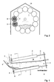
- the Figures show a drum structure 1 which is set up by a plurality of mutually parallel brush-shaped elements 2. These brush-shaped elements are journalled at and near their ends in flange-shaped elements 3 and 4, respectively. They therefore extend from the flange-shaped element 3 to a distance from the flange-shaped element 4.
- the brush-shaped elements 2 are formed by shafts 5 having substantially radially directed bristles, preferably of a synthetic material, such as abralon (registered trademark) 6.12k46. The ends of the parts of two adjacent brush-shaped elements directed towards each other touch or practically touch each other.
- the drum structure set up by the brush-shaped elements 2 therefore forms a closed whole. Conversely, the part of the drum structure near the flange-shaped element 4 shows open spaces between the shafts 5.
- a conveying element 6 for collecting and discharging the mussels fallen between the shafts 5.
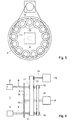
- the drum structure 1 is driven from the side where the flange-shaped element 4 is located; this flange-shaped element is designed as a closed plate.
- the flange-shaped element 3 is provided with an inlet opening 7 for mussels to be cleaned. Through this inlet opening 7 projects a chute 8 via which mussels to be cleaned can be introduced into the drum structure 1.
- the flange-shaped elements 3 and 4 are rotatably supported on a supporting frame, not shown, by means of rollers. Resting on these rollers, the drum structure 1 can be driven by a motor 9 with a controllable speed, of which motor the driven shaft 10 is fixedly mounted on the flange-shaped element 4. In order to drive the brush-shaped elements 3 around their own shafts 5, each of these shafts 5 is rotatably journalled in the flange-shaped elements 3 and 4 and is provided at the end projecting through the flange-shaped elements 4 with two pulleys or toothed wheels 11 and 12.
- a transmission element 16 Passed over the pulleys or toothed wheels 11 of a plurality of shafts 5 and a pulley or toothed wheel 13 around the driven shaft 14 of a motor 15 is a transmission element 16, such as a driving belt, rope or chain.
- a further transmission element 17, such as a driving belt, rope or chain is passed around the pulleys or toothed wheels 12.
- a water supply pipe 18 Through the free space in the drum structure 1 is further arranged, via the inlet opening 7, a water supply pipe 18.
- this supply pipe 18 On one side, this supply pipe 18 is mounted on the supporting frame of the drum structure, and on the other side, this supply pipe rests in a case which is connected with the tip of the end of the driven shaft 10 projecting through the flange-shaped element 4.
- the supply pipe 18 is provided with openings for spraying mussels present in the drum structure.
- lifting means are provided in the form of a, in this exemplary embodiment hydraulic, cylinder to enable the adjustment of the position of the drum structure. These lifting means, not shown, engage the supporting frame of the drum structure 1. Finally, it is stated that plate-shaped protective means 19 may be provided around the drum structure and the driving means.
- the drum structure 1 is brought into an inclined position by means of the above lifting means, that is in a position as shown in Fig. 1, which inclined position takes place at an angle of 3 to 12°, and preferably of 6 to 8°.
- the drum structure 1 and the brush-shaped elements 2 are set in movement to a rotational speed for the drum structure 1 in the interval of 30 to 40 revolutions per minute and for the brush-shaped elements 2 to a rotational speed in the interval of 300 to 400 revolutions per minute.
- the correct speeds will depend on, inter alia, the degree of fouling of the mussels.
- the mussels are rinsed with water via the chute 8 in and through the drum structure and then, at the back of the drum structure, discharged via the spaces between the shafts 5 and the conveying element 6. At the same time, they are sprayed via the openings in the water supply pipe 18.
- the water runs between the brush-shaped elements 2 to the ground or to water discharge means.
- the throughput speed of the mussels is substantially determined by the adjustment, on the basis of the size and the degree of fouling of the mussel supplies, of the inclined position of the drum structure and by the amount of water and the size of the pressure of the water used for spraying the mussels in and through the drum structure.
Landscapes
- Life Sciences & Earth Sciences (AREA)
- Engineering & Computer Science (AREA)
- Food Science & Technology (AREA)
- Zoology (AREA)
- Chemical & Material Sciences (AREA)
- Marine Sciences & Fisheries (AREA)
- Health & Medical Sciences (AREA)
- Nutrition Science (AREA)
- Wood Science & Technology (AREA)
- Polymers & Plastics (AREA)
- Cleaning In General (AREA)
- Brushes (AREA)
- Processing Of Meat And Fish (AREA)
- Encapsulation Of And Coatings For Semiconductor Or Solid State Devices (AREA)
- Mechanical Treatment Of Semiconductor (AREA)
- Detergent Compositions (AREA)
- Farming Of Fish And Shellfish (AREA)
Claims (15)
- Verfahren zum Reinigen von Muschelschalen, insbesondere zum Entfernen von Rankenfüßern und/oder Zementschichten von den Muschelschalen, das eine Schleif- oder Bürstbehandlung der Muscheln In einer Drehtrommelkonstruktion (1) umfasst, die aus bürstenförmigen Elementen (2) besteht, die sich in gleicher Weise um ihre Achsen (5) drehen.
- Verfahren nach Anspruch 1, dadurch gekennzeichnet, dass die zu reinigenden Muscheln in der und durch die Trommelkonstruktion (1) in einer nach oben schrägen Richtung unter Wasserdruck gespült werden.
- Verfahren nach Anspruch 2, dadurch gekennzeichnet, dass die gewünschte Durchsatzgeschwindigkeit der Muscheln durch die Einstellung der Schrägstellung der Trommelkonstruktion (1) und der zum Spülen der Muscheln in der und durch die Trommelkonstruktion (1) verwendeten Wassermenge aufgrund der Größe und des Ausmaßes des Bewuchses der Muschelzufuhr erhalten wird.
- Verfahren nach Anspruch 3, dadurch gekennzeichnet, dass die Schrägstellung in einem Winkel von 3 bis 12°, vorzugsweise jedoch von 6 bis 8°, erfolgt.
- Verfahren nach einem der vorhergehenden Ansprüche, dadurch gekennzeichnet, dass die Drehzahl der bürstenförmigen Elemente (2) in dem Bereich von 300 bis 400 Umdrehungen je Minute liegt.
- Verfahren nach einem der vorhergehenden Ansprüche, dadurch gekennzeichnet, dass die Drehzahl der Trommelkonstruktion (1) in dem Bereich von 30 bis 40 Umdrehungen je Minute liegt.
- Vorrichtung zum Reinigen von Muschelschalen, insbesondere zum Entfernen von Rankenfüßern und/oder Zementschichten von den Muschelschalen, mit einer Vielzahl von zueinander parallelen bürstenförmigen Elementen (2), die zusammen eine Trommelkonstruktion (1) bilden und die an oder nahe ihren Enden in flanschförmigen Elementen (3, 4) drehbar gelagert sind, wobei weiterhin erste Antriebsmittel zum miteinander synchronen Antreiben der bürstenförmigen Elemente (2) sowie zweite Antriebsmittel zum Antreiben der gesamten Trommelkonstruktion mit den flanschförmigen Elementen (3, 4) vorgesehen sind.
- Vorrichtung nach Anspruch 7, dadurch gekennzeichnet, dass die ersten Antriebsmittel aus einem vorderen Getriebe-Element (16), um eine miteinander synchrone Bewegung der bürstenförmigen Elemente zu ermöglichen, und einem ersten Motor mit regelbarer Drehzahl und einem zweiten Getriebe-Element zum Antreiben eines oder mehrerer bürstenförmiger Elemente bestehen.
- Vorrichtung nach Anspruch 7 oder 8, dadurch gekennzeichnet, dass die zweiten Antriebsmittel aus einem zweiten Motor mit regelbarer Drehzahl bestehen, der in eines der flanschförmigen Elemente (3, 4) eingreift.
- Vorrichtung nach einem der Ansprüche 7 - 9, dadurch gekennzeichnet, dass die büratenförmigen Elemente (2) aus Wellen mit im Wesentlichen radial ausgerichteten Borsten gebildet sind, während die Enden der Teile von zwei übereinander liegenden bürstenförmigen Elementen (2), die gegeneinander gerichtet sind, einander berühren oder praktisch berühren.
- Vorrichtung nach einem der Ansprüche 7 - 10, dadurch gekennzeichnet, dass eines der flanschförmigen Elemente (3) mit einer Einlassöffnung (7) versehen ist, dass die bürstenförmigen Elemente (2) von diesem flanschförmigen Element (3) in einem Abstand von dem anderen flanschförmigen Element (4) verlaufen und dass Auslassöffnungen von den Zwischenräumen zwischen den Wellen (5) der bürstenförmigen Elemente (2) nahe dem anderen flanschförmigen Element (4) gebildet werden.
- Vorrichtung nach Anspruch 11, dadurch gekennzeichnet, dass unter den Auslassöffnungen ein Transportelement (6) für in der Trommelkonstruktion zu reinigende Muscheln angeordnet ist.
- Vorrichtung nach einem der Ansprüche 7 - 12, dadurch gekennzeichnet, dass eine Wasserversorgungsieltung (18) mit Öffnungen zum Besprühen der in der Trommelkonstruktion (1) befindlichen Muschein durch den freien Raum in der Trommelkonstruktion (1) angeordnet ist
- Vorrichtung nach einem der Ansprüche 7 - 13, dadurch gekennzeichnet, dass Hebemittel vorgesehen sind, um die Trommeikonstruktion (1) in einem solchen Winkel, dass die Einlassöffnung (7) den untersten Teil bildet, in die Betriebsstellung zu bringen.
- Vorrichtung nach einem der Ansprüche 7 - 14, dadurch gekennzeichnet, dass eine durch die Einlassöffnung (7) führende Rutsche (8) vorgesehen ist, über die Muschelschalen in der und durch die Trommelkonstruktion (1) unter Wasserdruck gespült werden können.
Applications Claiming Priority (2)
| Application Number | Priority Date | Filing Date | Title |
|---|---|---|---|
| NL1014547A NL1014547C2 (nl) | 2000-03-02 | 2000-03-02 | Werkwijze en inrichting voor het reinigen van mosselschelpen. |
| NL1014547 | 2000-03-02 |
Publications (2)
| Publication Number | Publication Date |
|---|---|
| EP1129622A1 EP1129622A1 (de) | 2001-09-05 |
| EP1129622B1 true EP1129622B1 (de) | 2004-06-02 |
Family
ID=19770930
Family Applications (1)
| Application Number | Title | Priority Date | Filing Date |
|---|---|---|---|
| EP01200765A Expired - Lifetime EP1129622B1 (de) | 2000-03-02 | 2001-03-01 | Verfahren und Vorrichtung zur Reinigung von Muschelschalen |
Country Status (5)
| Country | Link |
|---|---|
| EP (1) | EP1129622B1 (de) |
| AT (1) | ATE268121T1 (de) |
| DE (1) | DE60103570D1 (de) |
| NL (1) | NL1014547C2 (de) |
| NO (1) | NO20011058L (de) |
Families Citing this family (6)
| Publication number | Priority date | Publication date | Assignee | Title |
|---|---|---|---|---|
| EP1371294A1 (de) * | 2002-06-14 | 2003-12-17 | Cortech Protect B.V. | Krustentiereverarbeitungsmaschine und Krustentiereverarbeitungsverfahren |
| CN104206508B (zh) * | 2014-09-29 | 2016-03-30 | 福州大学 | 一种自动鲍鱼肉清洗装置 |
| CN108576182A (zh) * | 2018-05-30 | 2018-09-28 | 张蕾 | 一种扇贝清洗装置 |
| FR3100688B1 (fr) * | 2019-09-17 | 2021-12-03 | Axel Briere | Dispositif de lavage et système de traitement de coquillages |
| CN110810491B (zh) * | 2019-11-30 | 2022-03-04 | 浙江省海洋水产研究所 | 一种蛤类连续清洗系统 |
| CN112493303A (zh) * | 2020-12-16 | 2021-03-16 | 阳江市平海水产制品有限公司 | 鱼鳞去除机 |
Family Cites Families (8)
| Publication number | Priority date | Publication date | Assignee | Title |
|---|---|---|---|---|
| JPS6054663A (ja) * | 1983-09-05 | 1985-03-29 | Kinji Nagamatsu | 海苔の連続洗浄、脱水装置 |
| DE3425884A1 (de) * | 1984-07-13 | 1986-01-23 | Ritzer, Josef, 8203 Oberaudorf | Verfahren und vorrichtung zum putzen von schalentieren |
| US4601080A (en) * | 1985-04-29 | 1986-07-22 | Cook Terrence E | Washing apparatus |
| US4939814A (en) * | 1989-11-17 | 1990-07-10 | Tillion Diana R | Cultured mussel cleaning machine |
| JPH03195452A (ja) * | 1989-12-26 | 1991-08-27 | Ishinomaki Suisan Tekko:Kk | 魚体洗浄装置 |
| JPH05153903A (ja) * | 1991-12-09 | 1993-06-22 | Erickson Trauschi | ホタテ貝クリーナ |
| FR2720601B1 (fr) * | 1993-09-09 | 1996-12-13 | Eric Besnard | Dégrappeuse à moules et autres coquillages. |
| JPH11178502A (ja) * | 1997-12-18 | 1999-07-06 | Taiyo Seisakusho:Kk | 魚体の表面処理装置 |
-
2000
- 2000-03-02 NL NL1014547A patent/NL1014547C2/nl not_active IP Right Cessation
-
2001
- 2001-03-01 NO NO20011058A patent/NO20011058L/no not_active Application Discontinuation
- 2001-03-01 EP EP01200765A patent/EP1129622B1/de not_active Expired - Lifetime
- 2001-03-01 DE DE60103570T patent/DE60103570D1/de not_active Expired - Lifetime
- 2001-03-01 AT AT01200765T patent/ATE268121T1/de not_active IP Right Cessation
Also Published As
| Publication number | Publication date |
|---|---|
| NO20011058D0 (no) | 2001-03-01 |
| DE60103570D1 (de) | 2004-07-08 |
| NL1014547C2 (nl) | 2001-09-04 |
| NO20011058L (no) | 2001-09-03 |
| EP1129622A1 (de) | 2001-09-05 |
| ATE268121T1 (de) | 2004-06-15 |
Similar Documents
| Publication | Publication Date | Title |
|---|---|---|
| CA1093413A (en) | Apparatus for peeling fruits and vegetables | |
| CA1299324C (en) | Oscillating line travel pipe cleaning machine | |
| JPH06343439A (ja) | 果物または野菜の皮剥き装置 | |
| US1670809A (en) | Meat-washing machine | |
| CN107626513B (zh) | 一种五金产品门把手喷漆装置 | |
| EP1129622A1 (de) | Verfahren und Vorrichtung zur Reinigung von Muschelschalen | |
| CA2066562A1 (en) | Surface treatment | |
| CA2245414C (en) | Apparatus for removing barnacles from crustacean shells | |
| CN110558363B (zh) | 一种不伤鱼身的自动打鳞机 | |
| JPS62235119A (ja) | コンベアベルトのクリ−ニング装置 | |
| CN106106694A (zh) | 贝类自动生产装置及方法 | |
| CN206043265U (zh) | 一种贝类自动加工设备 | |
| CN106106695A (zh) | 贝类自动加工设备及方法 | |
| CA2552778A1 (en) | Apparatus and method for processing fur | |
| CN206043264U (zh) | 一种自动清洗装置 | |
| CN213908229U (zh) | 一种肉食品加工用除毛装置 | |
| CN106070527A (zh) | 自动清洗装置 | |
| CN211298359U (zh) | 一种柚子加工用毛刷清洗机 | |
| EP0847705A1 (de) | Trommelspühlmaschine mit Schmutzentfernungsmitteln | |
| JP3411534B2 (ja) | 魚のウロコ取り装置 | |
| EP1371294A1 (de) | Krustentiereverarbeitungsmaschine und Krustentiereverarbeitungsverfahren | |
| CN209493016U (zh) | 一种具有清扫功能的皮带运输装置 | |
| JPH07289666A (ja) | スクリュー式ゴルフボール洗浄機 | |
| KR200190667Y1 (ko) | 밤탈피장치 | |
| CN113729244A (zh) | 一种猕猴桃清洗设备 |
Legal Events
| Date | Code | Title | Description |
|---|---|---|---|
| PUAI | Public reference made under article 153(3) epc to a published international application that has entered the european phase |
Free format text: ORIGINAL CODE: 0009012 |
|
| AK | Designated contracting states |
Kind code of ref document: A1 Designated state(s): AT BE CH CY DE DK ES FI FR GB GR IE IT LI LU MC NL PT SE TR |
|
| AX | Request for extension of the european patent |
Free format text: AL;LT;LV;MK;RO;SI |
|
| 17P | Request for examination filed |
Effective date: 20020304 |
|
| AKX | Designation fees paid |
Free format text: AT BE CH CY DE DK ES FI FR GB GR IE IT LI LU MC NL PT SE TR |
|
| 17Q | First examination report despatched |
Effective date: 20020619 |
|
| GRAP | Despatch of communication of intention to grant a patent |
Free format text: ORIGINAL CODE: EPIDOSNIGR1 |
|
| GRAS | Grant fee paid |
Free format text: ORIGINAL CODE: EPIDOSNIGR3 |
|
| GRAA | (expected) grant |
Free format text: ORIGINAL CODE: 0009210 |
|
| AK | Designated contracting states |
Kind code of ref document: B1 Designated state(s): AT BE CH CY DE DK ES FI FR GB GR IE IT LI LU MC NL PT SE TR |
|
| PG25 | Lapsed in a contracting state [announced via postgrant information from national office to epo] |
Ref country code: AT Free format text: LAPSE BECAUSE OF FAILURE TO SUBMIT A TRANSLATION OF THE DESCRIPTION OR TO PAY THE FEE WITHIN THE PRESCRIBED TIME-LIMIT Effective date: 20040602 Ref country code: LI Free format text: LAPSE BECAUSE OF FAILURE TO SUBMIT A TRANSLATION OF THE DESCRIPTION OR TO PAY THE FEE WITHIN THE PRESCRIBED TIME-LIMIT Effective date: 20040602 Ref country code: FR Free format text: LAPSE BECAUSE OF FAILURE TO SUBMIT A TRANSLATION OF THE DESCRIPTION OR TO PAY THE FEE WITHIN THE PRESCRIBED TIME-LIMIT Effective date: 20040602 Ref country code: FI Free format text: LAPSE BECAUSE OF FAILURE TO SUBMIT A TRANSLATION OF THE DESCRIPTION OR TO PAY THE FEE WITHIN THE PRESCRIBED TIME-LIMIT Effective date: 20040602 Ref country code: CH Free format text: LAPSE BECAUSE OF FAILURE TO SUBMIT A TRANSLATION OF THE DESCRIPTION OR TO PAY THE FEE WITHIN THE PRESCRIBED TIME-LIMIT Effective date: 20040602 Ref country code: TR Free format text: LAPSE BECAUSE OF FAILURE TO SUBMIT A TRANSLATION OF THE DESCRIPTION OR TO PAY THE FEE WITHIN THE PRESCRIBED TIME-LIMIT Effective date: 20040602 Ref country code: IT Free format text: LAPSE BECAUSE OF FAILURE TO SUBMIT A TRANSLATION OF THE DESCRIPTION OR TO PAY THE FEE WITHIN THE PRESCRIBED TIME-LIMIT;WARNING: LAPSES OF ITALIAN PATENTS WITH EFFECTIVE DATE BEFORE 2007 MAY HAVE OCCURRED AT ANY TIME BEFORE 2007. THE CORRECT EFFECTIVE DATE MAY BE DIFFERENT FROM THE ONE RECORDED. Effective date: 20040602 |
|
| REG | Reference to a national code |
Ref country code: GB Ref legal event code: FG4D |
|
| REG | Reference to a national code |
Ref country code: CH Ref legal event code: EP |
|
| REF | Corresponds to: |
Ref document number: 60103570 Country of ref document: DE Date of ref document: 20040708 Kind code of ref document: P |
|
| REG | Reference to a national code |
Ref country code: IE Ref legal event code: FG4D |
|
| PG25 | Lapsed in a contracting state [announced via postgrant information from national office to epo] |
Ref country code: DK Free format text: LAPSE BECAUSE OF FAILURE TO SUBMIT A TRANSLATION OF THE DESCRIPTION OR TO PAY THE FEE WITHIN THE PRESCRIBED TIME-LIMIT Effective date: 20040902 Ref country code: GR Free format text: LAPSE BECAUSE OF FAILURE TO SUBMIT A TRANSLATION OF THE DESCRIPTION OR TO PAY THE FEE WITHIN THE PRESCRIBED TIME-LIMIT Effective date: 20040902 Ref country code: SE Free format text: LAPSE BECAUSE OF FAILURE TO SUBMIT A TRANSLATION OF THE DESCRIPTION OR TO PAY THE FEE WITHIN THE PRESCRIBED TIME-LIMIT Effective date: 20040902 |
|
| PG25 | Lapsed in a contracting state [announced via postgrant information from national office to epo] |
Ref country code: DE Free format text: LAPSE BECAUSE OF FAILURE TO SUBMIT A TRANSLATION OF THE DESCRIPTION OR TO PAY THE FEE WITHIN THE PRESCRIBED TIME-LIMIT Effective date: 20040903 |
|
| PG25 | Lapsed in a contracting state [announced via postgrant information from national office to epo] |
Ref country code: ES Free format text: LAPSE BECAUSE OF FAILURE TO SUBMIT A TRANSLATION OF THE DESCRIPTION OR TO PAY THE FEE WITHIN THE PRESCRIBED TIME-LIMIT Effective date: 20040913 |
|
| REG | Reference to a national code |
Ref country code: CH Ref legal event code: PL |
|
| PG25 | Lapsed in a contracting state [announced via postgrant information from national office to epo] |
Ref country code: IE Free format text: LAPSE BECAUSE OF NON-PAYMENT OF DUE FEES Effective date: 20050301 Ref country code: GB Free format text: LAPSE BECAUSE OF NON-PAYMENT OF DUE FEES Effective date: 20050301 Ref country code: CY Free format text: LAPSE BECAUSE OF FAILURE TO SUBMIT A TRANSLATION OF THE DESCRIPTION OR TO PAY THE FEE WITHIN THE PRESCRIBED TIME-LIMIT Effective date: 20050301 Ref country code: LU Free format text: LAPSE BECAUSE OF NON-PAYMENT OF DUE FEES Effective date: 20050301 |
|
| PG25 | Lapsed in a contracting state [announced via postgrant information from national office to epo] |
Ref country code: MC Free format text: LAPSE BECAUSE OF NON-PAYMENT OF DUE FEES Effective date: 20050331 |
|
| PLBE | No opposition filed within time limit |
Free format text: ORIGINAL CODE: 0009261 |
|
| STAA | Information on the status of an ep patent application or granted ep patent |
Free format text: STATUS: NO OPPOSITION FILED WITHIN TIME LIMIT |
|
| 26N | No opposition filed |
Effective date: 20050303 |
|
| EN | Fr: translation not filed | ||
| GBPC | Gb: european patent ceased through non-payment of renewal fee |
Effective date: 20050301 |
|
| REG | Reference to a national code |
Ref country code: IE Ref legal event code: MM4A |
|
| PG25 | Lapsed in a contracting state [announced via postgrant information from national office to epo] |
Ref country code: PT Free format text: LAPSE BECAUSE OF NON-PAYMENT OF DUE FEES Effective date: 20041102 |
|
| PGFP | Annual fee paid to national office [announced via postgrant information from national office to epo] |
Ref country code: NL Payment date: 20080318 Year of fee payment: 8 |
|
| PGFP | Annual fee paid to national office [announced via postgrant information from national office to epo] |
Ref country code: BE Payment date: 20080416 Year of fee payment: 8 |
|
| BERE | Be: lapsed |
Owner name: *MOSSELHANDEL TRITON B.V. Effective date: 20090331 |
|
| NLV4 | Nl: lapsed or anulled due to non-payment of the annual fee |
Effective date: 20091001 |
|
| PG25 | Lapsed in a contracting state [announced via postgrant information from national office to epo] |
Ref country code: NL Free format text: LAPSE BECAUSE OF NON-PAYMENT OF DUE FEES Effective date: 20091001 Ref country code: BE Free format text: LAPSE BECAUSE OF NON-PAYMENT OF DUE FEES Effective date: 20090331 |