EP1129745A2 - Structure d'électrode - Google Patents
Structure d'électrode Download PDFInfo
- Publication number
- EP1129745A2 EP1129745A2 EP01250066A EP01250066A EP1129745A2 EP 1129745 A2 EP1129745 A2 EP 1129745A2 EP 01250066 A EP01250066 A EP 01250066A EP 01250066 A EP01250066 A EP 01250066A EP 1129745 A2 EP1129745 A2 EP 1129745A2
- Authority
- EP
- European Patent Office
- Prior art keywords
- electrode
- electrode line
- fastening element
- arrangement according
- line
- Prior art date
- Legal status (The legal status is an assumption and is not a legal conclusion. Google has not performed a legal analysis and makes no representation as to the accuracy of the status listed.)
- Granted
Links
- 210000004165 myocardium Anatomy 0.000 claims abstract description 16
- 230000000149 penetrating effect Effects 0.000 claims 1
- 239000002184 metal Substances 0.000 description 23
- 230000000638 stimulation Effects 0.000 description 9
- 230000002051 biphasic effect Effects 0.000 description 5
- 238000009413 insulation Methods 0.000 description 5
- 229920001296 polysiloxane Polymers 0.000 description 5
- 230000028161 membrane depolarization Effects 0.000 description 4
- 230000008602 contraction Effects 0.000 description 3
- 210000001147 pulmonary artery Anatomy 0.000 description 2
- 210000005241 right ventricle Anatomy 0.000 description 2
- 230000004913 activation Effects 0.000 description 1
- 230000002146 bilateral effect Effects 0.000 description 1
- 230000000694 effects Effects 0.000 description 1
- 210000005240 left ventricle Anatomy 0.000 description 1
- 230000002035 prolonged effect Effects 0.000 description 1
- 230000004936 stimulating effect Effects 0.000 description 1
- 230000007704 transition Effects 0.000 description 1
- 238000003466 welding Methods 0.000 description 1
Images


Classifications
-
- A—HUMAN NECESSITIES
- A61—MEDICAL OR VETERINARY SCIENCE; HYGIENE
- A61N—ELECTROTHERAPY; MAGNETOTHERAPY; RADIATION THERAPY; ULTRASOUND THERAPY
- A61N1/00—Electrotherapy; Circuits therefor
- A61N1/02—Details
- A61N1/04—Electrodes
- A61N1/05—Electrodes for implantation or insertion into the body, e.g. heart electrode
- A61N1/056—Transvascular endocardial electrode systems
- A61N1/057—Anchoring means; Means for fixing the head inside the heart
- A61N1/0573—Anchoring means; Means for fixing the head inside the heart chacterised by means penetrating the heart tissue, e.g. helix needle or hook
Definitions
- the invention relates to an electrode arrangement with an electrode line, which carries at least one first fastening element for fastening the electrode line on body tissue, especially the myocardium of a heart and is arranged at a distance from the distal end of the electrode line.
- the invention relates in particular to an electrode line with electrodes for Stimulating the myorcardia of a human heart or for recording electrical signals from a human heart.
- Such electrode lines are mainly used in connection with an implanted pacemaker, which stimulates artificially via the electrodes of the electrode line.
- Electrode arrangements for Stimulation of the septum are, for example, from DE 195 46 941, the US 5,728,140, US 5,683,447, US 5,476,500 and US 5,693,081. None of these electrode lines satisfactorily permits biphasic Upper septal stimulation.
- the electrode cable is also anchored not solved satisfactorily in the septum in the known electrode arrangements.
- the invention has the object Reason to offer an alternative electrode arrangement, the disadvantages described avoid the state of the art as far as possible.
- this object is achieved by an electrode arrangement type mentioned at the beginning, in which the first fastening element with the electrode line is firmly connected and has at least one free end, which a Extension component with respect to the electrode line in the tangential direction has and is designed such that the first fastening element by a Rotary movement of the electrode lead penetrates body tissue around its longitudinal axis.
- Electrode line movable fasteners such as those from the US patent documents 5,476,500, 5,683,447 and 5,693,081 are known.
- the first fastening element is as Helix coil formed, which is rigidly connected to the electrode line, so that the helix coil essentially coaxially at a distance from the electrode line Loops around the electrode lead.
- the first fastener is thus corkscrew-like trained and rigidly connected to the electrode line.
- the free end of the fastener hooks by rotating the electrode line around it Longitudinal axis in adjacent body tissue and thus ensures a safe Attachment of the electrode lead to the body tissue. This enables in particular an active fixation on the septum of a heart.
- the corridors of the Spirals preferably have a constant distance from one another, like the corkscrew corridors.
- the free end is of the fastener preferably sharpened.
- the first fastening means is preferably at the distal end of the Electrode lead attached so that the free end of the first fastener is closer to the proximal end of the electrode lead.
- a corkscrew convoluted second fastener with opposite Direction of rotation at the distal end of the electrode line can, as described below, avoid stress on the electrode lead in the case of a contracting myocardium become.
- the first fastening element has a second free end, which is related to the electrode line has the same tangential orientation as the first free end, but an opposite axial orientation, with the first fastener is attached to the electrode line between the two free ends.
- Such central fastening of the first fastening element to the electrode line has two free ends because of the opposite direction of rotation of the two resulting Helix sections the advantage that when screwing in Helix sections in adjacent tissue a certain amount of tension between the two free ends against each other. This tension leads to a safe one Fixation of the otherwise releasable rather by unintentional rotary movements Attachment.
- the electrode arrangement preferably carries a second fastening element its distal end.
- Such an electrode arrangement can at two points, namely at its distal end and at a distance from it actively on the body tissue are attached so that the two fasteners also with respect to Body tissue in a fixed position to each other.
- the second fastening element is also preferably of the corkscrew type formed as a helical coil with a free end, the second fastening element a direction of rotation opposite to the first fastening element owns. If the second fastener is rigid with the electrode lead is connected, the electrode line can move around its proximal end Longitudinal axis are rotated in this way, both fasteners in the to allow the same senses to penetrate into neighboring body tissue. As a result of opposite direction of rotation of the two fasteners and the hereby in directly related measure, the first fastener to attach to the electrode lead with its distal end will Myocardium is compressed between the two when the fasteners are screwed in. In this way, high loads on the electrode line in the case of Contraction of the myocardium avoided.
- a drive for the second fastener can also be provided be, which allows the second fastener regardless of the To drive the electrode line about its longitudinal axis, preferably from the proximal end of the electrode lead.
- a drive for the second fastener is active fixable screw electrodes known per se at the distal end of the electrode line.
- An electrode arrangement which has a first electrode is particularly preferred an electrically conductive surface on the free end of the first fastening element has adjacent surface of the electrode line.
- the first fastening element is preferably with the first Electrode electrically connected and in this way becomes a component itself the first electrode.
- the first electrode is also preferred from the surface of the first fastening element wrapped around the Electrode line formed.
- the electrode arrangement preferably has at least one second electrode its distal end.
- a second electrode especially in the immediate vicinity Neighborhood to the second fastener, which is preferably Part of the second electrode allows the delivery of bipolar, in particular biphasic Stimulation impulses to the body tissue.
- the biphasic stimulation impulses can overlap in time.
- An electrode arrangement which has exactly two fastening elements comprises, which are designed as corkscrew-like helical spirals, each provided with a free end designed to penetrate tissue and removed on the one hand at the distal end of the electrode lead and on the other hand of these are arranged, and at least two electrodes with electrically conductive Surface, each in the immediate vicinity of the fasteners are arranged.
- Such an electrode arrangement advantageously allows biphasic stimulation of a heart's high septum.
- the electrode line preferably further comprises two coaxial, electrical conductive coils, which face each other and the outside of the electrode line are electrically insulated and of which the outer coil is from the distal end of the Electrode lead contacted first electrode during the inner coil contacted the electrode at the distal end of the electrode lead.
- Such Electrode lead is highly flexible without the risk of breakage of the electrically conductive coils.
- Such an electrode line also provides reliable contacting of the electrodes.
- the electrode line also preferably has control means with which the distal end is deflected in the bilateral direction in a manner known per se can be. This allows the electrode line to be guided to it in a targeted manner Destination.
- control means are known, for example, from US Patents 5,254,088, 5,364,351, 5,376,109 and 5,423,884 as well as EP 0 667 126 and DE 35 07 119 known.
- FIG. 1 shows that part of an electrode line 10 that is at its distal end 12 connects.
- a first electrode 14 and a first fastening element 16 are provided.
- the first fastening element 16 is rigidly fastened to the electrode line 10 and loops around the electrode line 10 in the manner of a corkscrew at a distance to the electrode line 10.
- the looped area of the electrode line 10 is formed as a first electrode 14 and has an electrically conductive surface.
- the first fastening element 16 is at the distal end of the first electrode 14 attached so that there is a pointed free end 40 of the first fastener 16 is located near the proximal end of the first electrode 14.
- This arrangement has the advantage of problems such as hooking the free end 40 of the first fastening element 16 when the electrode line 10 is inserted for example in a human heart.
- a second electrode 20 as Tip electrode provided.
- a second fastener at distal end 12 22 attached, which is also of a corkscrew-shaped Metal wire is formed, the free end for active attachment in one Heart into whose myocardium can be screwed. To do this, the whole Electrode line 10 rotated about its longitudinal axis.
- the second fastener 22 is connected to the second electrode 20 such that the second Fastening element 22 becomes part of the second electrode.
- the second Electrode 20 is otherwise from an electrically conductive surface of the electrode line 10 formed at the distal end 12 thereof.
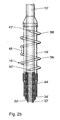
- FIG. 2a shows the area of the first electrode 14 and the first fastening element 16 of the electrode line 10 in detail.
- an inner wire coil 30 can be seen, which is from a hose-like silicone insulation 32 is surrounded and the tip electrode 20th leads and contacts them electrically.
- silicone insulation 32 is surrounded by a second wire coil 34, the inner wire coil 30 and the tubular silicone insulation 32 coaxial surrounds.
- the outer wire coil 34 contacts the first at its distal end Electrode 14, which is formed by a metal sleeve 36, which the inner wire coil 30 and coaxially encloses the hose-like silicone insulation 32.
- the metal sleeve 36 forming the first electrode 14 is corkscrew-like at one end spiral metal helix 38 firmly, for example by welding, with the distal end of the metal sleeve 36 connected.
- the corkscrew-like metal helix 38 forms the first fastener 16 and is shaped so that the coils of the Metal helix is spaced from each other and to the metal sleeve 36 these wind.
- the metal helix 38 has an essentially tangential orientation Pointed free end 40 protruding freely into the space, which by Rotate the entire electrode line 10 about its longitudinal axis into the adjacent one Body tissue can penetrate.
- the pointed free end 40 is in the Proximity of the proximal end of the first electrode 14.
- the metal helix 38 is designed so that the free end 40 by rotating the Counterclockwise electrode line 10 penetrates into adjacent myocardium and in this way the myocardium in close contact with the first electrode 14 brings. This includes, for example, two and a half revolutions of the electrode line required.
- the metal helix 38 accordingly has two courses and extends about 80% of the length of the first electrode 14.
- the chosen design and Attachment of the metal helix 38 also has the effect that the myocardium at Screwing in the first fastening element 16 in the direction of the tip electrode 22 is pushed that, if you will, the myocardium between the two Electrodes is slightly compressed. This reduces stress on the electrodes and the electrode lead during contraction of the myocardium.
- the outer wire coil 34 is of an outer tubular silicone insulation 44 surrounded.
- the electrode arrangement thus has exactly two on the outside electrically active components, on the one hand by the tip electrode 20 and the second fastener 22 are formed and the other from the metal sleeve 36 and the metal helix 38.
- Control or guide wires inside the electrode line are not shown, the control and routing of the electrode line in a known manner serve lateral deflection of the distal end 12 of the electrode line.
- FIG. 2b shows an embodiment 16 'of the first fastening element differs from the fastener 16 of Figure 2a in that the alternative fastening element 16'2 has pointed free ends 40 'and 42'.
- the two free ends 40 'and 42' are at the end of two opposite ends Metal helices 38r and 381, of which the metal helix 38r is clockwise while the metal helix 381 is left-turning.
- the two metal helices 38r and 381 start from a central portion 46 of the fastener 16 ', the for fastening the first fastening element 16 'in the electrode 14' with this is welded.
- the first fastening element 16 ' is thus in the middle between its two free ends 40 'and 42' connected to the electrode 14 '.
- Metal helices 381 and 38r of the metal helix 38 from FIG. 2a.
- Metal helices 381 and 38r against each other and thus ensure a secure fixation of the first fastening element 16 'in the body tissue.
- FIG. 3 shows a human heart 50 in the sectional view, in which the Electrode line 10 with the first electrode 14 and the second electrode 20 is inserted such that the tip electrode 20 abuts the high septum 52, and the first electrode 14 also on septum 52 at a predetermined distance from second electrode 20. Both fasteners 16 and 22 are by axial Rotation of the electrode line 10 is screwed into the septum 52 about its longitudinal axis.
- a particular advantage of the arrangement shown is biphasic stimulation of the high septum with overlapping impulses that a possible alternative to biventricular stimulation for patients with prolonged interventricular transition time.
- the electrode line is at its proximal end with a known per se implantable pacemaker connected to the inner and outer Coil 30 and 34 contacted separately, so that to the first electrode 14 and second electrode 20 emitted electrical pulses independently of one another can be.
- the special design of the two fastening elements 16 and 22 allow an active fixation of the electrode line at two locations on the septum 52, in which the distal end 12 of the electrode line 10 directly on the trunk of the right Pulmonary artery is fastened in the high septum while the first fastener 16 somewhat away from this but still engages in the high septum.
- the arrangement of the first and second electrodes 14, which can be seen in FIG. 3 and 20 and the first and second fasteners 16 and 22 is both the design of the fasteners 16 and 22 as well as the distance of the Electrodes 14 and 20 and the corresponding fastening elements 16 and 22 predefined on the electrode line 10.
- the depolarization follows the natural conduction paths, which run within the septum, so that a delay of the Interventricular activation is avoided, as with the usual stimulation occurs in the apex of the right ventricle. This way the natural physiological dynamics of the contraction of the heart restored.
Landscapes
- Health & Medical Sciences (AREA)
- Cardiology (AREA)
- Heart & Thoracic Surgery (AREA)
- Vascular Medicine (AREA)
- Engineering & Computer Science (AREA)
- Biomedical Technology (AREA)
- Nuclear Medicine, Radiotherapy & Molecular Imaging (AREA)
- Radiology & Medical Imaging (AREA)
- Life Sciences & Earth Sciences (AREA)
- Animal Behavior & Ethology (AREA)
- General Health & Medical Sciences (AREA)
- Public Health (AREA)
- Veterinary Medicine (AREA)
- Electrotherapy Devices (AREA)
- Surgical Instruments (AREA)
Applications Claiming Priority (2)
| Application Number | Priority Date | Filing Date | Title |
|---|---|---|---|
| DE10011572 | 2000-03-02 | ||
| DE10011572A DE10011572A1 (de) | 2000-03-02 | 2000-03-02 | Elektrodenanordnung |
Publications (3)
| Publication Number | Publication Date |
|---|---|
| EP1129745A2 true EP1129745A2 (fr) | 2001-09-05 |
| EP1129745A3 EP1129745A3 (fr) | 2001-11-07 |
| EP1129745B1 EP1129745B1 (fr) | 2005-07-20 |
Family
ID=7634147
Family Applications (1)
| Application Number | Title | Priority Date | Filing Date |
|---|---|---|---|
| EP01250066A Expired - Lifetime EP1129745B1 (fr) | 2000-03-02 | 2001-03-01 | Structure d'électrode |
Country Status (3)
| Country | Link |
|---|---|
| US (1) | US6556874B2 (fr) |
| EP (1) | EP1129745B1 (fr) |
| DE (2) | DE10011572A1 (fr) |
Cited By (1)
| Publication number | Priority date | Publication date | Assignee | Title |
|---|---|---|---|---|
| EP1243286B1 (fr) * | 2001-03-21 | 2014-03-05 | BIOTRONIK SE & Co. KG | Fil d'électrode intravasculaire |
Families Citing this family (41)
| Publication number | Priority date | Publication date | Assignee | Title |
|---|---|---|---|---|
| DE10162508A1 (de) * | 2001-12-19 | 2003-07-03 | Biotronik Mess & Therapieg | Epikardelektrodenleitung, Einführkatheter für eine solche und Elektrodenimplantationsbesteck |
| FR2841476B1 (fr) * | 2002-06-26 | 2005-03-11 | Ela Medical Sa | Sonde coronaire comprenant des moyens perfectionnes de retenue |
| US7082335B2 (en) * | 2002-09-30 | 2006-07-25 | Medtronic, Inc. | Multipolar pacing method and apparatus |
| SG171468A1 (en) * | 2002-12-10 | 2011-06-29 | Nikon Corp | Exposure apparatus and method for producing device |
| US7392094B2 (en) | 2002-12-19 | 2008-06-24 | Cardiac Pacemakers, Inc. | Implantable lead for septal placement of pacing electrodes |
| US20040147994A1 (en) * | 2003-01-28 | 2004-07-29 | Cardiac Pacemakers, Inc. | Tachy lead system optimized for septal placement |
| US20050055058A1 (en) * | 2003-09-08 | 2005-03-10 | Mower Morton M. | Method and apparatus for intrachamber resynchronization |
| US7251532B2 (en) * | 2003-10-17 | 2007-07-31 | Medtronic, Inc. | Medical lead fixation |
| US7647109B2 (en) * | 2004-10-20 | 2010-01-12 | Boston Scientific Scimed, Inc. | Leadless cardiac stimulation systems |
| US7532933B2 (en) * | 2004-10-20 | 2009-05-12 | Boston Scientific Scimed, Inc. | Leadless cardiac stimulation systems |
| CA2583404A1 (fr) | 2004-10-20 | 2006-04-27 | Boston Scientific Limited | Systemes de stimulation cardiaque sans fil |
| US7720550B2 (en) * | 2004-12-03 | 2010-05-18 | Medtronic, Inc. | High impedance active fixation electrode of an electrical medical lead |
| US8326423B2 (en) | 2004-12-20 | 2012-12-04 | Cardiac Pacemakers, Inc. | Devices and methods for steering electrical stimulation in cardiac rhythm management |
| US8290586B2 (en) | 2004-12-20 | 2012-10-16 | Cardiac Pacemakers, Inc. | Methods, devices and systems for single-chamber pacing using a dual-chamber pacing device |
| US8423139B2 (en) | 2004-12-20 | 2013-04-16 | Cardiac Pacemakers, Inc. | Methods, devices and systems for cardiac rhythm management using an electrode arrangement |
| US8050756B2 (en) | 2004-12-20 | 2011-11-01 | Cardiac Pacemakers, Inc. | Circuit-based devices and methods for pulse control of endocardial pacing in cardiac rhythm management |
| US8005544B2 (en) | 2004-12-20 | 2011-08-23 | Cardiac Pacemakers, Inc. | Endocardial pacing devices and methods useful for resynchronization and defibrillation |
| US8010191B2 (en) | 2004-12-20 | 2011-08-30 | Cardiac Pacemakers, Inc. | Systems, devices and methods for monitoring efficiency of pacing |
| US8014861B2 (en) | 2004-12-20 | 2011-09-06 | Cardiac Pacemakers, Inc. | Systems, devices and methods relating to endocardial pacing for resynchronization |
| AR047851A1 (es) | 2004-12-20 | 2006-03-01 | Giniger Alberto German | Un nuevo marcapasos que restablece o preserva la conduccion electrica fisiologica del corazon y un metodo de aplicacion |
| US8010192B2 (en) | 2004-12-20 | 2011-08-30 | Cardiac Pacemakers, Inc. | Endocardial pacing relating to conduction abnormalities |
| US7848823B2 (en) | 2005-12-09 | 2010-12-07 | Boston Scientific Scimed, Inc. | Cardiac stimulation system |
| US8050774B2 (en) * | 2005-12-22 | 2011-11-01 | Boston Scientific Scimed, Inc. | Electrode apparatus, systems and methods |
| US7937161B2 (en) * | 2006-03-31 | 2011-05-03 | Boston Scientific Scimed, Inc. | Cardiac stimulation electrodes, delivery devices, and implantation configurations |
| US7860580B2 (en) * | 2006-04-24 | 2010-12-28 | Medtronic, Inc. | Active fixation medical electrical lead |
| US8290600B2 (en) * | 2006-07-21 | 2012-10-16 | Boston Scientific Scimed, Inc. | Electrical stimulation of body tissue using interconnected electrode assemblies |
| US7840281B2 (en) | 2006-07-21 | 2010-11-23 | Boston Scientific Scimed, Inc. | Delivery of cardiac stimulation devices |
| WO2008034005A2 (fr) * | 2006-09-13 | 2008-03-20 | Boston Scientific Scimed, Inc. | Stimulation cardiaque utilisant des ensembles électrodes sans fil |
| US8738147B2 (en) | 2008-02-07 | 2014-05-27 | Cardiac Pacemakers, Inc. | Wireless tissue electrostimulation |
| EP2384222A2 (fr) | 2008-12-19 | 2011-11-09 | Cardiac Pacemakers, Inc. | Dispositifs, procédés et systèmes comprenant une stimulation cardiaque |
| US8565880B2 (en) | 2010-04-27 | 2013-10-22 | Cardiac Pacemakers, Inc. | His-bundle capture verification and monitoring |
| WO2012125273A2 (fr) | 2011-03-14 | 2012-09-20 | Cardiac Pacemakers, Inc. | Vérification de capture de his à l'aide de retard électro-mécanique |
| US8755909B2 (en) | 2012-06-01 | 2014-06-17 | Medtronic, Inc. | Active fixation medical electrical lead |
| US10315028B2 (en) | 2014-04-23 | 2019-06-11 | Medtronic, Inc. | Active fixation medical electrical lead |
| EP3100762B1 (fr) * | 2015-06-02 | 2020-04-01 | BIOTRONIK SE & Co. KG | Produit medical diagnostic comprenant une structure de surface adhesive |
| US10195421B2 (en) | 2015-08-12 | 2019-02-05 | Medtronic, Inc. | Epicardial defibrilation lead with side helix fixation and placement thereof |
| WO2018089311A1 (fr) | 2016-11-08 | 2018-05-17 | Cardiac Pacemakers, Inc | Dispositif médical implantable pour déploiement auriculaire |
| EP3950053B1 (fr) | 2017-11-06 | 2023-06-21 | Pacesetter, Inc. | Biostimulateur ayant un élément de fixation |
| US11577086B2 (en) | 2018-08-20 | 2023-02-14 | Pacesetter, Inc. | Fixation mechanisms for a leadless cardiac biostimulator |
| USD894396S1 (en) | 2019-03-08 | 2020-08-25 | Pacesetter, Inc. | Leadless biostimulator attachment feature |
| US11541243B2 (en) | 2019-03-15 | 2023-01-03 | Pacesetter, Inc. | Biostimulator having coaxial fixation elements |
Citations (7)
| Publication number | Priority date | Publication date | Assignee | Title |
|---|---|---|---|---|
| US5254088A (en) | 1990-02-02 | 1993-10-19 | Ep Technologies, Inc. | Catheter steering mechanism |
| US5364351A (en) | 1992-11-13 | 1994-11-15 | Ep Technologies, Inc. | Catheter steering mechanism |
| US5376109A (en) | 1992-06-16 | 1994-12-27 | Siemens Aktiengesellschaft | Medical electrode device |
| US5476500A (en) | 1993-12-20 | 1995-12-19 | Ventritex, Inc. | Endocardial lead system with defibrillation electrode fixation |
| DE19546941A1 (de) | 1995-12-15 | 1997-06-19 | Biotronik Mess & Therapieg | Einzel-Elektrode für Zweikammer-Herzschrittmachersysteme, insbesondere für DDD-Herzschrittmachersysteme |
| US5683447A (en) | 1995-12-19 | 1997-11-04 | Ventritex, Inc. | Lead with septal defibrillation and pacing electrodes |
| US5728140A (en) | 1996-06-17 | 1998-03-17 | Cardiac Pacemakers, Inc. | Method for evoking capture of left ventricle using transeptal pacing lead |
Family Cites Families (14)
| Publication number | Priority date | Publication date | Assignee | Title |
|---|---|---|---|---|
| DE3020587A1 (de) * | 1980-05-30 | 1981-12-03 | Hans-Jürgen Dipl.-Ing. 5100 Aachen Bisping | Elektrodenzuleitung fuer implantierbare herzschrittmacher |
| DE3027587A1 (de) | 1980-07-21 | 1982-02-25 | Klöckner-Humboldt-Deutz AG, 5000 Köln | Brenner fuer feste brennstoffe |
| DE3507119A1 (de) | 1985-02-28 | 1986-08-28 | Siemens AG, 1000 Berlin und 8000 München | Regelbare endokardiale elektrodenanordnung |
| DE3529578A1 (de) * | 1985-08-17 | 1987-02-19 | Bisping Hans Juergen | Implantierbare elektrode |
| US5409453A (en) | 1992-08-12 | 1995-04-25 | Vidamed, Inc. | Steerable medical probe with stylets |
| SE9202480D0 (sv) * | 1992-08-28 | 1992-08-28 | Siemens Elema Ab | Elektrodanordning |
| SE9304031D0 (sv) * | 1993-12-03 | 1993-12-03 | Siemens Elema Ab | Elektrodsystem |
| US5443492A (en) | 1994-02-02 | 1995-08-22 | Medtronic, Inc. | Medical electrical lead and introducer system for implantable pulse generator |
| US5628778A (en) * | 1994-11-21 | 1997-05-13 | Medtronic Inc. | Single pass medical electrical lead |
| US5531783A (en) * | 1995-01-17 | 1996-07-02 | Vitatron Medical, B.V. | Pacing lead with x-ray visible soluble covering and method of inserting same into a patient's heart |
| US5571162A (en) | 1995-06-07 | 1996-11-05 | Intermedics, Inc. | Transvenous defibrillation lead with side hooks |
| US5755764A (en) * | 1996-09-10 | 1998-05-26 | Sulzer Intermedics Inc. | Implantable cardiac stimulation catheter |
| US5871532A (en) * | 1997-05-22 | 1999-02-16 | Sulzer Intermedics Inc. | Epicardial lead for minimally invasive implantation |
| CA2328867A1 (fr) | 1998-04-17 | 1999-10-28 | Yayun Lin | Systeme de sonde endocavitaire |
-
2000
- 2000-03-02 DE DE10011572A patent/DE10011572A1/de not_active Withdrawn
-
2001
- 2001-02-27 US US09/794,110 patent/US6556874B2/en not_active Expired - Lifetime
- 2001-03-01 EP EP01250066A patent/EP1129745B1/fr not_active Expired - Lifetime
- 2001-03-01 DE DE50106746T patent/DE50106746D1/de not_active Expired - Lifetime
Patent Citations (8)
| Publication number | Priority date | Publication date | Assignee | Title |
|---|---|---|---|---|
| US5254088A (en) | 1990-02-02 | 1993-10-19 | Ep Technologies, Inc. | Catheter steering mechanism |
| US5376109A (en) | 1992-06-16 | 1994-12-27 | Siemens Aktiengesellschaft | Medical electrode device |
| US5364351A (en) | 1992-11-13 | 1994-11-15 | Ep Technologies, Inc. | Catheter steering mechanism |
| US5476500A (en) | 1993-12-20 | 1995-12-19 | Ventritex, Inc. | Endocardial lead system with defibrillation electrode fixation |
| US5693081A (en) | 1993-12-20 | 1997-12-02 | Pacesetter, Inc. | Endocardial lead system with defibrillation electrode fixation |
| DE19546941A1 (de) | 1995-12-15 | 1997-06-19 | Biotronik Mess & Therapieg | Einzel-Elektrode für Zweikammer-Herzschrittmachersysteme, insbesondere für DDD-Herzschrittmachersysteme |
| US5683447A (en) | 1995-12-19 | 1997-11-04 | Ventritex, Inc. | Lead with septal defibrillation and pacing electrodes |
| US5728140A (en) | 1996-06-17 | 1998-03-17 | Cardiac Pacemakers, Inc. | Method for evoking capture of left ventricle using transeptal pacing lead |
Cited By (1)
| Publication number | Priority date | Publication date | Assignee | Title |
|---|---|---|---|---|
| EP1243286B1 (fr) * | 2001-03-21 | 2014-03-05 | BIOTRONIK SE & Co. KG | Fil d'électrode intravasculaire |
Also Published As
| Publication number | Publication date |
|---|---|
| US20010020179A1 (en) | 2001-09-06 |
| DE10011572A1 (de) | 2001-09-06 |
| EP1129745B1 (fr) | 2005-07-20 |
| US6556874B2 (en) | 2003-04-29 |
| DE50106746D1 (de) | 2005-08-25 |
| EP1129745A3 (fr) | 2001-11-07 |
Similar Documents
| Publication | Publication Date | Title |
|---|---|---|
| EP1129745B1 (fr) | Structure d'électrode | |
| DE69826546T2 (de) | Medizinische elektrische Leitung | |
| DE60019908T2 (de) | Koronarsinusleitung | |
| EP0692221B1 (fr) | Cathéter avec électrodes | |
| DE19957241B4 (de) | Elektrische Leitung für medizinische Zwecke und System zur Einführung derselben | |
| DE60124948T2 (de) | Leitungen für die gerichtete Hirnstimulation und-aufzeichnung | |
| EP1691704B1 (fr) | Sonde-electrode pour l'electrotherapie de tissue | |
| DE69528508T2 (de) | Medizinisches Elektrodensystem mit drehbarem Übertragungswerkzeug | |
| DE69824258T2 (de) | Herzschrittmacherleitung mit poröser Elektrode | |
| DE69318659T2 (de) | Elektrodensystem für Herzschrittmachern | |
| DE602004006152T2 (de) | Fixierung für medizinische leitungen | |
| DE2652195B2 (de) | Herzschrittmacherelektrodenanordnung | |
| EP0009732A1 (fr) | Cathéter pour stimulateur cardiaque | |
| EP0563614A1 (fr) | Electrode de défibrillation | |
| DE3523226A1 (de) | Defibrillations-elektrode | |
| DE69921469T2 (de) | Medizinische elektrodenleitung | |
| EP2711046A1 (fr) | Ligne d'électrodes et élément de raccordement pour implants électromédicaux | |
| DE69211941T2 (de) | Elektrode mit einziehbarer Verankerung für Elektroden-Katheter | |
| EP2059296B1 (fr) | Dispositif de défibrillation du coeur | |
| DE2533766A1 (de) | Transvenoese, implantierbare herzschrittmacherelektrode | |
| EP2679275B1 (fr) | Électrode épicardique de cartographie | |
| EP1285678B1 (fr) | Sonde à électrode unique pour système de stimulation cardiaque | |
| EP2085113B1 (fr) | Electrode bipolaire implantable | |
| DE19959655B4 (de) | Chirurgische Elektrode | |
| DE10009830C2 (de) | Temporäre Herzschrittmacher-Leitung |
Legal Events
| Date | Code | Title | Description |
|---|---|---|---|
| PUAI | Public reference made under article 153(3) epc to a published international application that has entered the european phase |
Free format text: ORIGINAL CODE: 0009012 |
|
| AK | Designated contracting states |
Kind code of ref document: A2 Designated state(s): CH DE FR GB IT LI NL Kind code of ref document: A2 Designated state(s): AT BE CH CY DE DK ES FI FR GB GR IE IT LI LU MC NL PT SE TR |
|
| AX | Request for extension of the european patent |
Free format text: AL;LT;LV;MK;RO;SI |
|
| PUAL | Search report despatched |
Free format text: ORIGINAL CODE: 0009013 |
|
| AK | Designated contracting states |
Kind code of ref document: A3 Designated state(s): AT BE CH CY DE DK ES FI FR GB GR IE IT LI LU MC NL PT SE TR |
|
| AX | Request for extension of the european patent |
Free format text: AL;LT;LV;MK;RO;SI |
|
| 17P | Request for examination filed |
Effective date: 20020507 |
|
| AKX | Designation fees paid |
Free format text: CH DE FR GB IT LI NL |
|
| 17Q | First examination report despatched |
Effective date: 20040629 |
|
| GRAP | Despatch of communication of intention to grant a patent |
Free format text: ORIGINAL CODE: EPIDOSNIGR1 |
|
| GRAS | Grant fee paid |
Free format text: ORIGINAL CODE: EPIDOSNIGR3 |
|
| GRAA | (expected) grant |
Free format text: ORIGINAL CODE: 0009210 |
|
| AK | Designated contracting states |
Kind code of ref document: B1 Designated state(s): CH DE FR GB IT LI NL |
|
| REG | Reference to a national code |
Ref country code: GB Ref legal event code: FG4D Free format text: NOT ENGLISH |
|
| REG | Reference to a national code |
Ref country code: CH Ref legal event code: EP Ref country code: CH Ref legal event code: NV Representative=s name: BRAUNPAT BRAUN EDER AG |
|
| GBT | Gb: translation of ep patent filed (gb section 77(6)(a)/1977) |
Effective date: 20050720 |
|
| REF | Corresponds to: |
Ref document number: 50106746 Country of ref document: DE Date of ref document: 20050825 Kind code of ref document: P |
|
| ET | Fr: translation filed | ||
| PLBE | No opposition filed within time limit |
Free format text: ORIGINAL CODE: 0009261 |
|
| STAA | Information on the status of an ep patent application or granted ep patent |
Free format text: STATUS: NO OPPOSITION FILED WITHIN TIME LIMIT |
|
| 26N | No opposition filed |
Effective date: 20060421 |
|
| PGFP | Annual fee paid to national office [announced via postgrant information from national office to epo] |
Ref country code: NL Payment date: 20090324 Year of fee payment: 9 |
|
| PGFP | Annual fee paid to national office [announced via postgrant information from national office to epo] |
Ref country code: IT Payment date: 20090326 Year of fee payment: 9 |
|
| REG | Reference to a national code |
Ref country code: NL Ref legal event code: V1 Effective date: 20101001 |
|
| PG25 | Lapsed in a contracting state [announced via postgrant information from national office to epo] |
Ref country code: NL Free format text: LAPSE BECAUSE OF NON-PAYMENT OF DUE FEES Effective date: 20101001 |
|
| PG25 | Lapsed in a contracting state [announced via postgrant information from national office to epo] |
Ref country code: IT Free format text: LAPSE BECAUSE OF NON-PAYMENT OF DUE FEES Effective date: 20100301 |
|
| REG | Reference to a national code |
Ref country code: DE Ref legal event code: R082 Ref document number: 50106746 Country of ref document: DE Representative=s name: RANDOLL, SOEREN, DIPL.-CHEM. UNIV. DR. RER. NA, DE |
|
| REG | Reference to a national code |
Ref country code: DE Ref legal event code: R081 Ref document number: 50106746 Country of ref document: DE Owner name: BIOTRONIK SE & CO. KG, DE Free format text: FORMER OWNER: BIOTRONIK MESS- UND THERAPIEGERAETE GMBH & CO. INGENIEURBUERO BERLIN, 12359 BERLIN, DE Effective date: 20111219 |
|
| PGFP | Annual fee paid to national office [announced via postgrant information from national office to epo] |
Ref country code: FR Payment date: 20120403 Year of fee payment: 12 |
|
| PGFP | Annual fee paid to national office [announced via postgrant information from national office to epo] |
Ref country code: GB Payment date: 20120322 Year of fee payment: 12 |
|
| GBPC | Gb: european patent ceased through non-payment of renewal fee |
Effective date: 20130301 |
|
| REG | Reference to a national code |
Ref country code: FR Ref legal event code: ST Effective date: 20131129 |
|
| PG25 | Lapsed in a contracting state [announced via postgrant information from national office to epo] |
Ref country code: FR Free format text: LAPSE BECAUSE OF NON-PAYMENT OF DUE FEES Effective date: 20130402 Ref country code: GB Free format text: LAPSE BECAUSE OF NON-PAYMENT OF DUE FEES Effective date: 20130301 |
|
| PGFP | Annual fee paid to national office [announced via postgrant information from national office to epo] |
Ref country code: DE Payment date: 20160315 Year of fee payment: 16 Ref country code: CH Payment date: 20160322 Year of fee payment: 16 |
|
| REG | Reference to a national code |
Ref country code: DE Ref legal event code: R119 Ref document number: 50106746 Country of ref document: DE |
|
| REG | Reference to a national code |
Ref country code: CH Ref legal event code: PL |
|
| PG25 | Lapsed in a contracting state [announced via postgrant information from national office to epo] |
Ref country code: DE Free format text: LAPSE BECAUSE OF NON-PAYMENT OF DUE FEES Effective date: 20171003 |
|
| PG25 | Lapsed in a contracting state [announced via postgrant information from national office to epo] |
Ref country code: LI Free format text: LAPSE BECAUSE OF NON-PAYMENT OF DUE FEES Effective date: 20170331 Ref country code: CH Free format text: LAPSE BECAUSE OF NON-PAYMENT OF DUE FEES Effective date: 20170331 |