EP1129745B1 - Structure d'électrode - Google Patents
Structure d'électrode Download PDFInfo
- Publication number
- EP1129745B1 EP1129745B1 EP01250066A EP01250066A EP1129745B1 EP 1129745 B1 EP1129745 B1 EP 1129745B1 EP 01250066 A EP01250066 A EP 01250066A EP 01250066 A EP01250066 A EP 01250066A EP 1129745 B1 EP1129745 B1 EP 1129745B1
- Authority
- EP
- European Patent Office
- Prior art keywords
- electrode
- electrode line
- fixing element
- arrangement according
- line
- Prior art date
- Legal status (The legal status is an assumption and is not a legal conclusion. Google has not performed a legal analysis and makes no representation as to the accuracy of the status listed.)
- Expired - Lifetime
Links
- 210000004165 myocardium Anatomy 0.000 claims description 16
- 238000003780 insertion Methods 0.000 claims description 2
- 230000037431 insertion Effects 0.000 claims description 2
- 230000000149 penetrating effect Effects 0.000 claims 1
- 239000002184 metal Substances 0.000 description 22
- 230000000638 stimulation Effects 0.000 description 9
- 230000002051 biphasic effect Effects 0.000 description 5
- 238000009413 insulation Methods 0.000 description 5
- 229920001296 polysiloxane Polymers 0.000 description 5
- 230000028161 membrane depolarization Effects 0.000 description 4
- 230000008602 contraction Effects 0.000 description 3
- 210000001147 pulmonary artery Anatomy 0.000 description 2
- 210000005241 right ventricle Anatomy 0.000 description 2
- 230000004913 activation Effects 0.000 description 1
- 238000004873 anchoring Methods 0.000 description 1
- 230000002146 bilateral effect Effects 0.000 description 1
- 230000000694 effects Effects 0.000 description 1
- 239000004615 ingredient Substances 0.000 description 1
- 210000005240 left ventricle Anatomy 0.000 description 1
- 230000035515 penetration Effects 0.000 description 1
- 238000003466 welding Methods 0.000 description 1
Images

Classifications
-
- A—HUMAN NECESSITIES
- A61—MEDICAL OR VETERINARY SCIENCE; HYGIENE
- A61N—ELECTROTHERAPY; MAGNETOTHERAPY; RADIATION THERAPY; ULTRASOUND THERAPY
- A61N1/00—Electrotherapy; Circuits therefor
- A61N1/02—Details
- A61N1/04—Electrodes
- A61N1/05—Electrodes for implantation or insertion into the body, e.g. heart electrode
- A61N1/056—Transvascular endocardial electrode systems
- A61N1/057—Anchoring means; Means for fixing the head inside the heart
- A61N1/0573—Anchoring means; Means for fixing the head inside the heart chacterised by means penetrating the heart tissue, e.g. helix needle or hook
Definitions
- the invention relates to an electrode arrangement with an electrode line, which carries at least a first fastener, which is used to attach the electrode line formed on body tissue, in particular the myocardium of a heart and is arranged at a distance from the distal end of the electrode line.
- the invention particularly relates to an electrode lead with electrodes for Stimulation of the myocardium of a human heart or for recording electrical signals from a human heart.
- Such electrode lines are mainly used in conjunction with an implanted pacemaker, which artificially stimulated via the electrodes of the electrode line.
- Electrode arrangements for Stimulation of the septum are known for example from DE 195 46 941, the US 5,728,140, US 5,683,447, US 5,476,500 and US 5,693,081. None of these electrode lines satisfactorily allows a biphasic Stimulation of the upper septum. Also, the anchoring of the electrode line not satisfactorily resolved in the septum in the known electrode arrangements. US 5,693,081 discloses the features of the preamble of claim 1.
- the invention is the task Basically, to provide an alternative electrode arrangement, the disadvantages described as far as possible avoids the prior art.
- Electrode lead movable fasteners as disclosed in the US patents 5,476,500, 5,683,447 and 5,693,081 are known.
- the first fastening element is as Helix coil formed which is rigidly connected to the electrode line, so that the helix helix substantially coaxially distances the electrode lead from the electrode lead Wraps around electrode lead.
- the first fastening element is thus corkscrew-like trained and rigidly connected to the electrode line.
- the free end of the fastener hooked by turning the electrode line to the Longitudinal axis in adjacent body tissue and thus ensures a safe Attachment of the electrode lead to the body tissue. This allows in particular an active fixation on the septum of a heart.
- the corridors of Coils preferably have a constant distance from each other, like the corridors of a corkscrew.
- the free end is preferably sharpened the fastener.
- the first attachment means is preferably with its distal end on the Attached electrode lead, so that the free end of the first fastener closer to the proximal end of the electrode lead. Together with a corkscrew wound second fastener with opposite Direction of rotation at the distal end of the electrode lead, as described below, avoiding stress on the electrode lead in a contracting myocardium become.
- the first fastening element a second free end, which with respect to the electrode line but has the same tangential orientation as the first free end an opposite axial orientation, wherein the first fastening element is attached between the two free ends on the electrode line.
- Such central attachment of the first Befest Trentselemntes on the electrode line with has two free ends because of the opposite direction of rotation of the two resulting Helix sections the advantage that when screwing the Helix sections in adjacent tissue a certain tension of the two free ends against each other sets. This tension leads to a safe Fixation of the otherwise rather by unintentional rotational movements solvable Mounting.
- the electrode arrangement according to the invention contributes to a second fastening element her distal end.
- Such an electrode arrangement can be arranged in two places, namely at its distal end and at a distance actively on the body tissue be fastened, so that the two fastening elements also with respect to Body tissue take a fixed position to each other.
- the second fastener after Korkenzieherart formed as helical coil with a free end, wherein the second fastening element a direction of rotation opposite to the first fastening element has.
- the electrode line can from its proximal end to their Longitudinal axis to be rotated in this way both fasteners in the same sense to penetrate into adjacent body tissue.
- the first fastener With its distal end to attach to the electrode line, the Myocardium compressed when screwing in the fasteners between the two. In this way, high loads on the electrode line in the case of Contraction of the myocardium avoided.
- the second fastener so rigidly connected to the Elektoden
- a drive for the second fastener be that allows the second fastener regardless of the Electrode line to drive rotating about its longitudinal axis, preferably from the proximal end of the electrode line.
- first fastener connected to the electrode line while the second Befest Trentselemnt by a guided in the electrode lead stylet is rotatable relative to the electrode line.
- This type of drive is for active fixable screw electrodes at the distal end of the electrode line known per se.
- an electrode assembly which has a first electrode an electrically conductive surface on the free end of the first fastener having adjacent surface of the electrode line.
- the electrode arrangement preferably has at least one second electrode at its distal end.
- a second electrode in particular in the immediate Neighborhood to the second fastener, which preferably Part of the second electrode, allows the delivery of bipolar, especially biphasic Stimulation impulses to the body tissue.
- the biphasic stimulation pulses can overlap in time.
- an electrode assembly which exactly two fasteners which are designed as corkscrew-like helix spirals, each provided with a free, designed for penetration into tissue end and on the one hand at the distal end of the electrode lead and on the other thereof are arranged, as well as at least two electrodes with electrically conductive Surface, each in the immediate vicinity of the fasteners are arranged.
- Such an electrode arrangement allows advantageously the biphasic stimulation of the high septum of a heart.
- the electrode line preferably further comprises two coaxial, electrically conductive coils which face each other and to the outside of the electrode line are electrically insulated and of which the outer coil of the distal end of the Electrode lead removed first electrode contacted while the inner coil contacted the electrode at the distal end of the electrode lead.
- Such Electrode line has a high flexibility, without the risk of breakage consists of electrically conductive coils.
- such an electrode line a secure contacting of the electrodes.
- the electrode line also preferably has control means with which deflected the distal end in a known manner in the bilateral direction can be. This allows a targeted guidance of the electrode line to her Destination.
- control means are known for example from US patents 5,254,088, 5,364,351, 5,376,109 and 5,423,884 and EP 0 667 126 and DE 35 07 119 known.
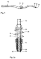
- FIG. 1 shows that part of an electrode line 10 which is at its distal end 12 connects.
- a first electrode 14 and a first fastening element 16 are provided.
- the first fastening element 16 is rigidly attached to the electrode line 10 and wraps around the electrode line 10 in a corkscrew fashion at a distance to the electrode line 10.
- the looped region of the electrode line 10 is formed as a first electrode 14 and has an electrically conductive surface.
- the first fastening element 16 is at the distal end of the first electrode 14 attached so that a sharpened free end 40 of the first fastener 16 is located near the proximal end of the first electrode 14.
- This arrangement has the advantage of problems such as catching the free end 40 of the first fastening element 16 during insertion of the electrode line 10th for example, in a human heart.
- a second electrode 20 as Tip electrode provided.
- a second fastener 22 attached, which also of a corkscrew-shaped Metal wire is formed, whose free end for active attachment in one Heart in which myocardium can be screwed. This is the whole Electrode line 10 is rotated about its longitudinal axis.
- the second fastener 22 is connected to the second electrode 20 such that the second Fastener 22 becomes part of the second electrode.
- electrode 20 becomes an electrically conductive surface of the electrode line 10 formed at the distal end 12.
- FIG. 2a shows the region of the first electrode 14 and of the first fastening element 16 of the electrode line 10 in detail.
- the electrode line 10 is an inner wire helix 30 can be seen, which from a tubular silicone insulation 32 is surrounded and to the tip electrode 20th leads and electrically contacted.
- the silicone insulation 32 is surrounded by a second wire coil 34, the inner wire coil 30 and the tubular silicone insulation 32 coaxial surrounds.
- the outer wire coil 34 contacts the first at its distal end Electrode 14, which is formed by a metal sleeve 36 which the inner wire helix 30 and the tubular silicone insulation 32 coaxially encloses.
- the first electrode 14 forming metal sleeve 36 is corkscrewed with one end wound metal helix 38 fixed, for example by welding, with the distal end of the metal sleeve 36 connected.
- the corkscrew-like metal helix 38 forms the first fastening element 16 and is shaped so that the helices of the Metal helix at a distance from each other and to the metal sleeve 36 um these wind.
- the metal helix 38 has a substantially tangentially aligned, cantilevered free end 40 projecting into space, passing through Turning the entire electrode line 10 into its adjacent longitudinal axis Body tissue can penetrate.
- the sharpened free end 40 is located in the Near the proximal end of the first electrode 14th
- the metal helix 38 is designed so that the free end 40 by turning the Lead electrode 10 counterclockwise penetrates into adjacent myocardium and in this way the myocardium is in close contact with the first electrode 14 brings. These are, for example, two and a half revolutions of the electrode line required.
- the metal helix 38 has two courses and extends about 80% of the length of the first electrode 14.
- the chosen design and Attachment of the metal helix 38 has the further effect that the myocardium Screwing the first fastening element 16 in the direction of the tip electrode 22nd it is postponed that, if you like, myocardium between the two Electrodes slightly compressed. This reduces stress on the electrodes and the electrode lead during contraction of the myocardium.
- the outer wire coil 34 is of an outer tubular silicone insulation 44 surrounded.
- the electrode assembly has exactly two outward electrically effective components, on the one hand by the tip electrode 20 and the second fastening element 22 are formed and the other of the metal sleeve 36 and the metal helix 38.
- control or guide wires inside the electrode lead in a known manner the controlling and guiding the electrode line lateral deflection of the distal end 12 serve the electrode line.
- FIG. 2b shows an embodiment 16 'of the first fastening element which differs from the fastener 16 of Figure 2a differs in that the alternative fastening element 16'2 pointed free ends 40 'and 42' has.
- the two free ends 40 'and 42' are at the end of two opposing Metal helices 38r and 38l, of which the metal helix 38r is dextrorotatory, while the metal helix 38l is left-handed.
- the two metal helices 38r and 38l emanate from a central portion 46 of the fastener 16 ', the for fixing the first fastening element 16 'in the electrode 14' with this is welded.
- the first fastening element 16 ' is thus centrally between its two free ends 40 'and 42' connected to the electrode 14 '.
- the correspond Metallhelices 38l and 38r of the metal helix 38 of Figure 2a When screwing the Metal helices 38l and 38r in adjacent body tissue tense the Metal helices 38l and 38r against each other and thus provide a secure fixation of the first fastener 16 'in the body tissue ago.
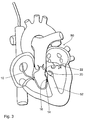
- FIG. 3 shows a human heart 50 in the sectional view into which the Electrode line 10 with the first electrode 14 and the second electrode 20th is inserted so that the tip electrode 20 rests against the high septum 52, and the first electrode 14 also at the septum 52 at a predetermined distance from second electrode 20. Both fasteners 16 and 22 are by axial Turning the electrode line 10 is screwed about its longitudinal axis in the septum 52.
- a particular advantage of the arrangement shown is a biphasic stimulation of the high septum with temporally overlapping impulses that allow a possible alternative to biventricular pacing for patients with extended interventricular conduction time is.
- the electrode line is at its proximal end with a known per se implantable pacemaker connected to the inner and the outer Spiral 30 and 34 separately contacted so that the first electrode 14 and the second electrode 20 independently of each other electrical impulses can be.
- the special configuration of the two fastening elements 16 and 22 allow an active fixation of the electrode line at two locations of the septum 52, in the the distal end 12 of the electrode line 10 directly on the trunk of the right Pulmonary artery is fixed in the high septum while the first fastener 16 away from it but still intervening in the high septum.
- removable arrangement of the first and second electrodes 14th and 20 and the first and second fastener 16 and 22 is both the design of the fasteners 16 and 22 and the distance of Electrodes 14 and 20 and the corresponding fasteners 16 and 22nd predetermined on the electrode line 10.
- the depolarization follows the natural conduction paths, which run within the septum, so that a delay of the interventricular activation is avoided, as in the usual stimulation occurs in the apex of the right ventricle. In this way, the natural becomes physiological dynamics of the contraction of the heart restored.
Landscapes
- Health & Medical Sciences (AREA)
- Cardiology (AREA)
- Heart & Thoracic Surgery (AREA)
- Vascular Medicine (AREA)
- Engineering & Computer Science (AREA)
- Biomedical Technology (AREA)
- Nuclear Medicine, Radiotherapy & Molecular Imaging (AREA)
- Radiology & Medical Imaging (AREA)
- Life Sciences & Earth Sciences (AREA)
- Animal Behavior & Ethology (AREA)
- General Health & Medical Sciences (AREA)
- Public Health (AREA)
- Veterinary Medicine (AREA)
- Electrotherapy Devices (AREA)
- Surgical Instruments (AREA)
Claims (15)
- Dispositif d'électrode équipé d'un fil d'électrode (10), qui comporte au moins un premier élément de fixation (16) et un second élément de fixation (22), qui sont réalisés en vue de la fixation d'un fil d'électrode à un tissu corporel, en particulier au myocarde du coeur,
dans lequel le premier élément de fixation (16) est disposé éloigné de l'extrémité distale (12) du fil d'électrode (10) et le second élément de fixation (22) est disposé à l'extrémité distale (12) du fil d'électrode (10),
caractérisé en ce que le premier élément de fixation (16) présente au moins un tronçon enroulé hélicoidalement, qui est relié de façon rigide au fil d'électrode (10), de sorte que le tronçon enroulé hélicoïdalement entoure le fil d'électrode (10) de façon sensiblement coaxiale éloigné du fil d'électrode (10) et présente une extrémité libre allant dans une direction proximale, qui présente un composant longitudinal par rapport à la direction tangentielle du fil d'électrode (10) et est réalisée de sorte que le premier élément de fixation (16) pénètre le tissu corporel voisin par un mouvement de rotation du fil d'électrode (10) autour de son axe longitudinal selon l'application,
et en ce que le second élément de fixation (22) est réalisé sous la forme d'une hélice avec une extrémité libre (40) selon la technique du tire-bouchon et le sens de rotation du second élément de fixation (22) est inversé par rapport à celui du premier élément de fixation. - Dispositif d'électrode selon la revendication 1, caractérisé en ce que les spires de l'hélice du tronçon enroulé en hélice du premier élément de fixation (16) sont éloignées les unes des autres dans la direction longitudinale du fil d'électrode (10).
- Dispositif d'électrode selon l'une des revendications 1 à 2, caractérisé en ce que la première extrémité libre du premier élément de fixation (40) est affûtée.
- Dispositif d'électrode selon l'une des revendications 1 à 3, caractérisé en ce que le premier élément de fixation (16) présente une seconde extrémité libre, laquelle possède la même direction tangentielle que la première extrémité libre par rapport au fil d'électrode (10) mais une direction axiale inversée, et en ce que le premier élément de fixation (16) est fixé entre deux extrémités libres au fil d'électrode (10).
- Dispositif d'électrode selon l'une des revendications 1 à 4, caractérisé en ce que le second élément de fixation (22) est relié au fil d'électrode (10) de sorte qu'il est entraíné en rotation conjointement avec le fil d'électrode par rotation du fil d'électrode autour de son axe longitudinal.
- Dispositif d'électrode selon la revendication 4, caractérisé par un entraínement, qui est relié au second élément de fixation (22) et est réalisé de sorte que le second élément de fixation (22) peut être entraíné à rotation indépendamment du fil d'électrode (10) autour de son axe longitudinal.
- Dispositif d'électrode selon la revendication 6, caractérisé en ce que l'entraínement est réalisé de sorte que le second élément de fixation (22) peut être entraíné à rotation depuis l'extrémité proximale du fil d'électrode (10) par rapport au reste du fil d'électrode (10).
- Dispositif d'électrode selon l'une des revendications 1 à 7, caractérisé par une première électrode (14) munie d'une surface électriquement conductrice sur la surface adjacente à l'extrémité libre (40) du premier élément de fixation (16) du fil d'électrode (10).
- Dispositif d'électrode selon la revendication 8, caractérisé en ce que la première électrode (14) est formée par la surface entourant le premier élément de fixation (16) du fil d'électrode (10).
- Dispositif d'électrode selon la revendication 8 ou 9, caractérisé en ce que le premier élément de fixation (16) est réalisé électriquement conducteur et est relié électriquement à la première électrode (14) de sorte que la première électrode (14) et le premier élément de fixation (16) fonctionnent conjointement comme une électrode destinée à délivrer des impulsions électriques ou à recevoir des signaux électriques.
- Dispositif d'électrode selon l'une des revendications 8 à 10, caractérisé en ce que le premier élément de fixation (16) est fixé au fil d'électrode (10) dans la zone de l'extrémité distale de la première électrode (14), tandis que la première extrémité libre (40) du premier élément de fixation (16) se trouve dans le voisinage de l'extrémité proximale de la première électrode (14).
- Dispositif d'électrode selon l'une des revendications 1 à 11, caractérisé par une seconde électrode (20) disposée à l'extrémité distale (12) du fil d'électrode (10).
- Dispositif d'électrode selon l'une des revendications 1 à 12, caractérisé par exactement deux éléments de fixation (16, 22), qui sont réalisés sous la forme d'hélices selon la technique du tire-bouchon avec respectivement une extrémité libre réalisée en vue de pénétrer dans un tissu et sont disposés d'une part à l'extrémité distale (12) du fil d'électrode (10) et d'autre part éloignés de celle-ci, ainsi que par au moins deux électrodes (14, 20) avec une surface électriquement conductrice, qui sont disposées respectivement au voisinage immédiat des moyens de fixation.
- Dispositif d'électrode selon l'une des revendications 11 et 12 ou 13, caractérisé en ce que le fil d'électrode (10) comprend deux hélices coaxiales électriquement conductrices, qui sont électriquement isolées l'une de l'autre et grâce auxquelles l'hélice externe vient en contact de la première électrode éloignée de l'extrémité distale du fil d'électrode (10), tandis que l'hélice interne vient en contact de l'électrode à l'extrémité distale du fil d'électrode (10).
- Dispositif d'électrode selon l'une des revendications 1 à 14, caractérisé par des moyens de commande à l'intérieur du fil d'électrode (10), qui sont réalisés de telle sorte que l'extrémité distale (12) du fil d'électrode (10) est déviée de l'extrémité proximale du fil d'électrode (10) latéralement dans une direction au choix.
Applications Claiming Priority (2)
| Application Number | Priority Date | Filing Date | Title |
|---|---|---|---|
| DE10011572 | 2000-03-02 | ||
| DE10011572A DE10011572A1 (de) | 2000-03-02 | 2000-03-02 | Elektrodenanordnung |
Publications (3)
| Publication Number | Publication Date |
|---|---|
| EP1129745A2 EP1129745A2 (fr) | 2001-09-05 |
| EP1129745A3 EP1129745A3 (fr) | 2001-11-07 |
| EP1129745B1 true EP1129745B1 (fr) | 2005-07-20 |
Family
ID=7634147
Family Applications (1)
| Application Number | Title | Priority Date | Filing Date |
|---|---|---|---|
| EP01250066A Expired - Lifetime EP1129745B1 (fr) | 2000-03-02 | 2001-03-01 | Structure d'électrode |
Country Status (3)
| Country | Link |
|---|---|
| US (1) | US6556874B2 (fr) |
| EP (1) | EP1129745B1 (fr) |
| DE (2) | DE10011572A1 (fr) |
Families Citing this family (42)
| Publication number | Priority date | Publication date | Assignee | Title |
|---|---|---|---|---|
| DE10114725A1 (de) * | 2001-03-21 | 2002-09-26 | Biotronik Mess & Therapieg | Intravaskuläre Elektrodenleitung |
| DE10162508A1 (de) * | 2001-12-19 | 2003-07-03 | Biotronik Mess & Therapieg | Epikardelektrodenleitung, Einführkatheter für eine solche und Elektrodenimplantationsbesteck |
| FR2841476B1 (fr) * | 2002-06-26 | 2005-03-11 | Ela Medical Sa | Sonde coronaire comprenant des moyens perfectionnes de retenue |
| US7082335B2 (en) * | 2002-09-30 | 2006-07-25 | Medtronic, Inc. | Multipolar pacing method and apparatus |
| SG171468A1 (en) * | 2002-12-10 | 2011-06-29 | Nikon Corp | Exposure apparatus and method for producing device |
| US7392094B2 (en) | 2002-12-19 | 2008-06-24 | Cardiac Pacemakers, Inc. | Implantable lead for septal placement of pacing electrodes |
| US20040147994A1 (en) * | 2003-01-28 | 2004-07-29 | Cardiac Pacemakers, Inc. | Tachy lead system optimized for septal placement |
| US20050055058A1 (en) | 2003-09-08 | 2005-03-10 | Mower Morton M. | Method and apparatus for intrachamber resynchronization |
| US7251532B2 (en) * | 2003-10-17 | 2007-07-31 | Medtronic, Inc. | Medical lead fixation |
| US7532933B2 (en) | 2004-10-20 | 2009-05-12 | Boston Scientific Scimed, Inc. | Leadless cardiac stimulation systems |
| CA2583404A1 (fr) | 2004-10-20 | 2006-04-27 | Boston Scientific Limited | Systemes de stimulation cardiaque sans fil |
| US7650186B2 (en) * | 2004-10-20 | 2010-01-19 | Boston Scientific Scimed, Inc. | Leadless cardiac stimulation systems |
| US7720550B2 (en) * | 2004-12-03 | 2010-05-18 | Medtronic, Inc. | High impedance active fixation electrode of an electrical medical lead |
| US8010191B2 (en) | 2004-12-20 | 2011-08-30 | Cardiac Pacemakers, Inc. | Systems, devices and methods for monitoring efficiency of pacing |
| US8014861B2 (en) | 2004-12-20 | 2011-09-06 | Cardiac Pacemakers, Inc. | Systems, devices and methods relating to endocardial pacing for resynchronization |
| US8326423B2 (en) | 2004-12-20 | 2012-12-04 | Cardiac Pacemakers, Inc. | Devices and methods for steering electrical stimulation in cardiac rhythm management |
| US8423139B2 (en) | 2004-12-20 | 2013-04-16 | Cardiac Pacemakers, Inc. | Methods, devices and systems for cardiac rhythm management using an electrode arrangement |
| US8050756B2 (en) | 2004-12-20 | 2011-11-01 | Cardiac Pacemakers, Inc. | Circuit-based devices and methods for pulse control of endocardial pacing in cardiac rhythm management |
| AR047851A1 (es) | 2004-12-20 | 2006-03-01 | Giniger Alberto German | Un nuevo marcapasos que restablece o preserva la conduccion electrica fisiologica del corazon y un metodo de aplicacion |
| US8010192B2 (en) * | 2004-12-20 | 2011-08-30 | Cardiac Pacemakers, Inc. | Endocardial pacing relating to conduction abnormalities |
| US8290586B2 (en) | 2004-12-20 | 2012-10-16 | Cardiac Pacemakers, Inc. | Methods, devices and systems for single-chamber pacing using a dual-chamber pacing device |
| US8005544B2 (en) | 2004-12-20 | 2011-08-23 | Cardiac Pacemakers, Inc. | Endocardial pacing devices and methods useful for resynchronization and defibrillation |
| WO2007067231A1 (fr) * | 2005-12-09 | 2007-06-14 | Boston Scientific Scimed, Inc. | Systeme de stimulation cardiaque |
| US8050774B2 (en) * | 2005-12-22 | 2011-11-01 | Boston Scientific Scimed, Inc. | Electrode apparatus, systems and methods |
| US7937161B2 (en) * | 2006-03-31 | 2011-05-03 | Boston Scientific Scimed, Inc. | Cardiac stimulation electrodes, delivery devices, and implantation configurations |
| US7860580B2 (en) * | 2006-04-24 | 2010-12-28 | Medtronic, Inc. | Active fixation medical electrical lead |
| US7840281B2 (en) * | 2006-07-21 | 2010-11-23 | Boston Scientific Scimed, Inc. | Delivery of cardiac stimulation devices |
| US8290600B2 (en) * | 2006-07-21 | 2012-10-16 | Boston Scientific Scimed, Inc. | Electrical stimulation of body tissue using interconnected electrode assemblies |
| US8644934B2 (en) * | 2006-09-13 | 2014-02-04 | Boston Scientific Scimed Inc. | Cardiac stimulation using leadless electrode assemblies |
| US8738147B2 (en) * | 2008-02-07 | 2014-05-27 | Cardiac Pacemakers, Inc. | Wireless tissue electrostimulation |
| AU2009327369B2 (en) | 2008-12-19 | 2012-10-11 | Cardiac Pacemakers, Inc. | Devices, methods, and systems including cardiac pacing |
| US8565880B2 (en) | 2010-04-27 | 2013-10-22 | Cardiac Pacemakers, Inc. | His-bundle capture verification and monitoring |
| US8761880B2 (en) | 2011-03-14 | 2014-06-24 | Cardiac Pacemakers, Inc. | His capture verification using electro-mechanical delay |
| US8755909B2 (en) | 2012-06-01 | 2014-06-17 | Medtronic, Inc. | Active fixation medical electrical lead |
| US10315028B2 (en) | 2014-04-23 | 2019-06-11 | Medtronic, Inc. | Active fixation medical electrical lead |
| EP3100763A1 (fr) * | 2015-06-02 | 2016-12-07 | BIOTRONIK SE & Co. KG | Électrode implantable comprenant une structure de surface adhesive |
| US10195421B2 (en) | 2015-08-12 | 2019-02-05 | Medtronic, Inc. | Epicardial defibrilation lead with side helix fixation and placement thereof |
| US10583301B2 (en) | 2016-11-08 | 2020-03-10 | Cardiac Pacemakers, Inc. | Implantable medical device for atrial deployment |
| CN111601640B (zh) | 2017-11-06 | 2024-04-09 | 先导者股份有限公司 | 具有固定元件的生物刺激器 |
| US11577086B2 (en) | 2018-08-20 | 2023-02-14 | Pacesetter, Inc. | Fixation mechanisms for a leadless cardiac biostimulator |
| USD894396S1 (en) | 2019-03-08 | 2020-08-25 | Pacesetter, Inc. | Leadless biostimulator attachment feature |
| US11541243B2 (en) | 2019-03-15 | 2023-01-03 | Pacesetter, Inc. | Biostimulator having coaxial fixation elements |
Family Cites Families (21)
| Publication number | Priority date | Publication date | Assignee | Title |
|---|---|---|---|---|
| DE3020587A1 (de) * | 1980-05-30 | 1981-12-03 | Hans-Jürgen Dipl.-Ing. 5100 Aachen Bisping | Elektrodenzuleitung fuer implantierbare herzschrittmacher |
| DE3027587A1 (de) | 1980-07-21 | 1982-02-25 | Klöckner-Humboldt-Deutz AG, 5000 Köln | Brenner fuer feste brennstoffe |
| DE3507119A1 (de) | 1985-02-28 | 1986-08-28 | Siemens AG, 1000 Berlin und 8000 München | Regelbare endokardiale elektrodenanordnung |
| DE3529578A1 (de) * | 1985-08-17 | 1987-02-19 | Bisping Hans Juergen | Implantierbare elektrode |
| US5254088A (en) | 1990-02-02 | 1993-10-19 | Ep Technologies, Inc. | Catheter steering mechanism |
| US5409453A (en) | 1992-08-12 | 1995-04-25 | Vidamed, Inc. | Steerable medical probe with stylets |
| SE9201846D0 (sv) | 1992-06-16 | 1992-06-16 | Siemens Elema Ab | Elektrodanordning |
| SE9202480D0 (sv) * | 1992-08-28 | 1992-08-28 | Siemens Elema Ab | Elektrodanordning |
| US5364351A (en) | 1992-11-13 | 1994-11-15 | Ep Technologies, Inc. | Catheter steering mechanism |
| SE9304031D0 (sv) * | 1993-12-03 | 1993-12-03 | Siemens Elema Ab | Elektrodsystem |
| US5476500A (en) | 1993-12-20 | 1995-12-19 | Ventritex, Inc. | Endocardial lead system with defibrillation electrode fixation |
| US5443492A (en) | 1994-02-02 | 1995-08-22 | Medtronic, Inc. | Medical electrical lead and introducer system for implantable pulse generator |
| US5628778A (en) * | 1994-11-21 | 1997-05-13 | Medtronic Inc. | Single pass medical electrical lead |
| US5531783A (en) * | 1995-01-17 | 1996-07-02 | Vitatron Medical, B.V. | Pacing lead with x-ray visible soluble covering and method of inserting same into a patient's heart |
| US5571162A (en) | 1995-06-07 | 1996-11-05 | Intermedics, Inc. | Transvenous defibrillation lead with side hooks |
| DE19546941A1 (de) | 1995-12-15 | 1997-06-19 | Biotronik Mess & Therapieg | Einzel-Elektrode für Zweikammer-Herzschrittmachersysteme, insbesondere für DDD-Herzschrittmachersysteme |
| US5683447A (en) * | 1995-12-19 | 1997-11-04 | Ventritex, Inc. | Lead with septal defibrillation and pacing electrodes |
| US5728140A (en) | 1996-06-17 | 1998-03-17 | Cardiac Pacemakers, Inc. | Method for evoking capture of left ventricle using transeptal pacing lead |
| US5755764A (en) * | 1996-09-10 | 1998-05-26 | Sulzer Intermedics Inc. | Implantable cardiac stimulation catheter |
| US5871532A (en) * | 1997-05-22 | 1999-02-16 | Sulzer Intermedics Inc. | Epicardial lead for minimally invasive implantation |
| CA2328867A1 (fr) | 1998-04-17 | 1999-10-28 | Yayun Lin | Systeme de sonde endocavitaire |
-
2000
- 2000-03-02 DE DE10011572A patent/DE10011572A1/de not_active Withdrawn
-
2001
- 2001-02-27 US US09/794,110 patent/US6556874B2/en not_active Expired - Lifetime
- 2001-03-01 EP EP01250066A patent/EP1129745B1/fr not_active Expired - Lifetime
- 2001-03-01 DE DE50106746T patent/DE50106746D1/de not_active Expired - Lifetime
Also Published As
| Publication number | Publication date |
|---|---|
| EP1129745A2 (fr) | 2001-09-05 |
| US6556874B2 (en) | 2003-04-29 |
| DE50106746D1 (de) | 2005-08-25 |
| EP1129745A3 (fr) | 2001-11-07 |
| DE10011572A1 (de) | 2001-09-06 |
| US20010020179A1 (en) | 2001-09-06 |
Similar Documents
| Publication | Publication Date | Title |
|---|---|---|
| EP1129745A2 (fr) | Structure d'électrode | |
| DE69826546T2 (de) | Medizinische elektrische Leitung | |
| DE60019908T2 (de) | Koronarsinusleitung | |
| DE19957241B4 (de) | Elektrische Leitung für medizinische Zwecke und System zur Einführung derselben | |
| EP0692221B1 (fr) | Cathéter avec électrodes | |
| DE69528508T2 (de) | Medizinisches Elektrodensystem mit drehbarem Übertragungswerkzeug | |
| DE69824258T2 (de) | Herzschrittmacherleitung mit poröser Elektrode | |
| DE69603191T2 (de) | Transvenöse defibrillierungsleitung mit seitenhaken | |
| DE602004006152T2 (de) | Fixierung für medizinische leitungen | |
| EP1062971A1 (fr) | Cathéter muni d'un port distal pour un fil | |
| EP0009732A1 (fr) | Cathéter pour stimulateur cardiaque | |
| EP3328482B1 (fr) | Systeme d'electrode a courant continu implantable | |
| DE19800697A1 (de) | Einzel-Elektrodensonde, insbesondere für implantierbare Defibrillatoren | |
| DE2533766C2 (de) | Implantierbare transvenös einführbare Herzschrittmacherleitung | |
| EP2059296B1 (fr) | Dispositif de défibrillation du coeur | |
| EP1285678B1 (fr) | Sonde à électrode unique pour système de stimulation cardiaque | |
| EP2085113B1 (fr) | Electrode bipolaire implantable | |
| DE19959655B4 (de) | Chirurgische Elektrode | |
| DE19963602A1 (de) | Zwei-Kammer Single-Pass Elektroden-Anordnung | |
| DE3304506A1 (de) | Elektrodenstecker fuer herzschrittmacher-elektrode | |
| DE10302319B4 (de) | Bipolare Stimulationselektrode | |
| DE2347720A1 (de) | Elektrische anordnung zum gebrauch als prothese | |
| EP2478933A2 (fr) | Appareil implantable | |
| EP2283894B1 (fr) | Conduite d'électrodes de stimulation | |
| DE10118797A1 (de) | Elektrodenleitung |
Legal Events
| Date | Code | Title | Description |
|---|---|---|---|
| PUAI | Public reference made under article 153(3) epc to a published international application that has entered the european phase |
Free format text: ORIGINAL CODE: 0009012 |
|
| AK | Designated contracting states |
Kind code of ref document: A2 Designated state(s): CH DE FR GB IT LI NL Kind code of ref document: A2 Designated state(s): AT BE CH CY DE DK ES FI FR GB GR IE IT LI LU MC NL PT SE TR |
|
| AX | Request for extension of the european patent |
Free format text: AL;LT;LV;MK;RO;SI |
|
| PUAL | Search report despatched |
Free format text: ORIGINAL CODE: 0009013 |
|
| AK | Designated contracting states |
Kind code of ref document: A3 Designated state(s): AT BE CH CY DE DK ES FI FR GB GR IE IT LI LU MC NL PT SE TR |
|
| AX | Request for extension of the european patent |
Free format text: AL;LT;LV;MK;RO;SI |
|
| 17P | Request for examination filed |
Effective date: 20020507 |
|
| AKX | Designation fees paid |
Free format text: CH DE FR GB IT LI NL |
|
| 17Q | First examination report despatched |
Effective date: 20040629 |
|
| GRAP | Despatch of communication of intention to grant a patent |
Free format text: ORIGINAL CODE: EPIDOSNIGR1 |
|
| GRAS | Grant fee paid |
Free format text: ORIGINAL CODE: EPIDOSNIGR3 |
|
| GRAA | (expected) grant |
Free format text: ORIGINAL CODE: 0009210 |
|
| AK | Designated contracting states |
Kind code of ref document: B1 Designated state(s): CH DE FR GB IT LI NL |
|
| REG | Reference to a national code |
Ref country code: GB Ref legal event code: FG4D Free format text: NOT ENGLISH |
|
| REG | Reference to a national code |
Ref country code: CH Ref legal event code: EP Ref country code: CH Ref legal event code: NV Representative=s name: BRAUNPAT BRAUN EDER AG |
|
| GBT | Gb: translation of ep patent filed (gb section 77(6)(a)/1977) |
Effective date: 20050720 |
|
| REF | Corresponds to: |
Ref document number: 50106746 Country of ref document: DE Date of ref document: 20050825 Kind code of ref document: P |
|
| ET | Fr: translation filed | ||
| PLBE | No opposition filed within time limit |
Free format text: ORIGINAL CODE: 0009261 |
|
| STAA | Information on the status of an ep patent application or granted ep patent |
Free format text: STATUS: NO OPPOSITION FILED WITHIN TIME LIMIT |
|
| 26N | No opposition filed |
Effective date: 20060421 |
|
| PGFP | Annual fee paid to national office [announced via postgrant information from national office to epo] |
Ref country code: NL Payment date: 20090324 Year of fee payment: 9 |
|
| PGFP | Annual fee paid to national office [announced via postgrant information from national office to epo] |
Ref country code: IT Payment date: 20090326 Year of fee payment: 9 |
|
| REG | Reference to a national code |
Ref country code: NL Ref legal event code: V1 Effective date: 20101001 |
|
| PG25 | Lapsed in a contracting state [announced via postgrant information from national office to epo] |
Ref country code: NL Free format text: LAPSE BECAUSE OF NON-PAYMENT OF DUE FEES Effective date: 20101001 |
|
| PG25 | Lapsed in a contracting state [announced via postgrant information from national office to epo] |
Ref country code: IT Free format text: LAPSE BECAUSE OF NON-PAYMENT OF DUE FEES Effective date: 20100301 |
|
| REG | Reference to a national code |
Ref country code: DE Ref legal event code: R082 Ref document number: 50106746 Country of ref document: DE Representative=s name: RANDOLL, SOEREN, DIPL.-CHEM. UNIV. DR. RER. NA, DE |
|
| REG | Reference to a national code |
Ref country code: DE Ref legal event code: R081 Ref document number: 50106746 Country of ref document: DE Owner name: BIOTRONIK SE & CO. KG, DE Free format text: FORMER OWNER: BIOTRONIK MESS- UND THERAPIEGERAETE GMBH & CO. INGENIEURBUERO BERLIN, 12359 BERLIN, DE Effective date: 20111219 |
|
| PGFP | Annual fee paid to national office [announced via postgrant information from national office to epo] |
Ref country code: FR Payment date: 20120403 Year of fee payment: 12 |
|
| PGFP | Annual fee paid to national office [announced via postgrant information from national office to epo] |
Ref country code: GB Payment date: 20120322 Year of fee payment: 12 |
|
| GBPC | Gb: european patent ceased through non-payment of renewal fee |
Effective date: 20130301 |
|
| REG | Reference to a national code |
Ref country code: FR Ref legal event code: ST Effective date: 20131129 |
|
| PG25 | Lapsed in a contracting state [announced via postgrant information from national office to epo] |
Ref country code: FR Free format text: LAPSE BECAUSE OF NON-PAYMENT OF DUE FEES Effective date: 20130402 Ref country code: GB Free format text: LAPSE BECAUSE OF NON-PAYMENT OF DUE FEES Effective date: 20130301 |
|
| PGFP | Annual fee paid to national office [announced via postgrant information from national office to epo] |
Ref country code: DE Payment date: 20160315 Year of fee payment: 16 Ref country code: CH Payment date: 20160322 Year of fee payment: 16 |
|
| REG | Reference to a national code |
Ref country code: DE Ref legal event code: R119 Ref document number: 50106746 Country of ref document: DE |
|
| REG | Reference to a national code |
Ref country code: CH Ref legal event code: PL |
|
| PG25 | Lapsed in a contracting state [announced via postgrant information from national office to epo] |
Ref country code: DE Free format text: LAPSE BECAUSE OF NON-PAYMENT OF DUE FEES Effective date: 20171003 |
|
| PG25 | Lapsed in a contracting state [announced via postgrant information from national office to epo] |
Ref country code: LI Free format text: LAPSE BECAUSE OF NON-PAYMENT OF DUE FEES Effective date: 20170331 Ref country code: CH Free format text: LAPSE BECAUSE OF NON-PAYMENT OF DUE FEES Effective date: 20170331 |