EP1129837A2 - Antriebsvorrichtung für Spritzgiessmaschine - Google Patents
Antriebsvorrichtung für Spritzgiessmaschine Download PDFInfo
- Publication number
- EP1129837A2 EP1129837A2 EP01104913A EP01104913A EP1129837A2 EP 1129837 A2 EP1129837 A2 EP 1129837A2 EP 01104913 A EP01104913 A EP 01104913A EP 01104913 A EP01104913 A EP 01104913A EP 1129837 A2 EP1129837 A2 EP 1129837A2
- Authority
- EP
- European Patent Office
- Prior art keywords
- screw shaft
- rotation
- shaft
- rotation transmission
- transmission shaft
- Prior art date
- Legal status (The legal status is an assumption and is not a legal conclusion. Google has not performed a legal analysis and makes no representation as to the accuracy of the status listed.)
- Granted
Links
Images

Classifications
-
- B—PERFORMING OPERATIONS; TRANSPORTING
- B29—WORKING OF PLASTICS; WORKING OF SUBSTANCES IN A PLASTIC STATE IN GENERAL
- B29C—SHAPING OR JOINING OF PLASTICS; SHAPING OF MATERIAL IN A PLASTIC STATE, NOT OTHERWISE PROVIDED FOR; AFTER-TREATMENT OF THE SHAPED PRODUCTS, e.g. REPAIRING
- B29C45/00—Injection moulding, i.e. forcing the required volume of moulding material through a nozzle into a closed mould; Apparatus therefor
- B29C45/17—Component parts, details or accessories; Auxiliary operations
- B29C45/76—Measuring, controlling or regulating
-
- B—PERFORMING OPERATIONS; TRANSPORTING
- B29—WORKING OF PLASTICS; WORKING OF SUBSTANCES IN A PLASTIC STATE IN GENERAL
- B29C—SHAPING OR JOINING OF PLASTICS; SHAPING OF MATERIAL IN A PLASTIC STATE, NOT OTHERWISE PROVIDED FOR; AFTER-TREATMENT OF THE SHAPED PRODUCTS, e.g. REPAIRING
- B29C45/00—Injection moulding, i.e. forcing the required volume of moulding material through a nozzle into a closed mould; Apparatus therefor
- B29C45/17—Component parts, details or accessories; Auxiliary operations
- B29C45/64—Mould opening, closing or clamping devices
- B29C45/66—Mould opening, closing or clamping devices mechanical
-
- B—PERFORMING OPERATIONS; TRANSPORTING
- B29—WORKING OF PLASTICS; WORKING OF SUBSTANCES IN A PLASTIC STATE IN GENERAL
- B29C—SHAPING OR JOINING OF PLASTICS; SHAPING OF MATERIAL IN A PLASTIC STATE, NOT OTHERWISE PROVIDED FOR; AFTER-TREATMENT OF THE SHAPED PRODUCTS, e.g. REPAIRING
- B29C45/00—Injection moulding, i.e. forcing the required volume of moulding material through a nozzle into a closed mould; Apparatus therefor
- B29C45/17—Component parts, details or accessories; Auxiliary operations
- B29C2045/1784—Component parts, details or accessories not otherwise provided for; Auxiliary operations not otherwise provided for
- B29C2045/1792—Machine parts driven by an electric motor, e.g. electric servomotor
- B29C2045/1794—Machine parts driven by an electric motor, e.g. electric servomotor by a rotor or directly coupled electric motor, e.g. using a tubular shaft motor
-
- Y—GENERAL TAGGING OF NEW TECHNOLOGICAL DEVELOPMENTS; GENERAL TAGGING OF CROSS-SECTIONAL TECHNOLOGIES SPANNING OVER SEVERAL SECTIONS OF THE IPC; TECHNICAL SUBJECTS COVERED BY FORMER USPC CROSS-REFERENCE ART COLLECTIONS [XRACs] AND DIGESTS
- Y10—TECHNICAL SUBJECTS COVERED BY FORMER USPC
- Y10T—TECHNICAL SUBJECTS COVERED BY FORMER US CLASSIFICATION
- Y10T74/00—Machine element or mechanism
- Y10T74/18—Mechanical movements
- Y10T74/18568—Reciprocating or oscillating to or from alternating rotary
- Y10T74/18576—Reciprocating or oscillating to or from alternating rotary including screw and nut
Definitions
- the invention relates to a drive apparatus for an injection molding machine.
- the mold apparatus comprises a stationary mold and a movable mold.
- the movable mold is advanced and retracted by a mold clamping apparatus so that the movable mold is attached to and separated from the stationary mold, to thereby perform mold closing, mold clamping and mold opening.
- the mold clamping apparatus has a toggle mechanism to advance and retract the movable mold.
- the toggle mechanism is driven by an electric motor or a servomotor in a drive section.
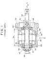
- Fig. 1 is a sectional view of a drive section of a conventional mold clamping apparatus.
- the servomotor 31 as a drive means has a motor case which comprises a plate-shaped first flange 54 to attach the servomotor 31 to a toggle support not illustrated, a plate-shaped second flange 55 spaced apart from the first flange 54, and a cylindrical frame 62 disposed between the first flange 54 and the second flange 55.
- a rotor 60 and a stator 61 are disposed inside the motor case.
- a hollow output shaft 50 is rotatably disposed relative to the motor case. Its rear end (leftward end in Fig. 1) is supported by a thrust bearing 57 while its front end (rightward end in Fig. 1) is supported by a thrust bearing 58. By these thrust bearings 57 and 58, the output shaft 50 is supported in a thrust direction and is rotatably supported in a radial direction.
- the stator 61 is fixed to the frame 62 and the rotor 60 is fixed to the output shaft 50.
- a coil 45 is mounted to the stator 61.
- Bolts 59 connect the first flange 54 and the second flange 55. By tightening the bolts 59, the frame 62 is pressed against the first flange 54 by the second flange 55.
- An encoder 48 is attached to the second flange 55 via a bracket 47.
- a fixing nut 46 is threadably engaged with it.
- a nut 51 is fixed to it by bolts 53. Therefore, by tightening the bolts 53, the thrust bearings 57 and 58 are pressed by the fixing nut 46 and the nut 51.
- a screw shaft 63 extends inside the output shaft 50, engages threadably with the nut 51, and then further extends forward (rightward in Fig. 1) to a cross head not illustrated. Its front end is connected to the cross head on which a toggle mechanism is disposed. The cross head is prevented from rotating by a guide bar not illustrated.
- a drive section comprises the servomotor 31, the output shaft 50, the nut 51, the screw shaft 63 and the cross head.
- the cross head When the screw shaft 63 is advanced (moved rightward in Fig. 1), the cross head is also advanced so that the toggle mechanism extends and advances the movable platen not illustrated, to thereby perform mold closing and mold clamping. When the screw shaft 63 is retracted (moved leftward in Fig. 1), the cross head is also retracted so that the toggle mechanism contracts the movable platen, to thereby perform mold opening.
- a mold clamping apparatus with a fixed nut and a rotated screw shaft is provided.
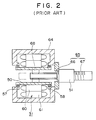
- Fig. 2 is a sectional view of a drive section of another conventional mold apparatus. With respect to the elements which have the same structure as the mold clamping apparatus in Fig. 1, the explanations of them are omitted by giving the same numeral to them.
- the hollow output shaft 50 is rotatably disposed relative to a motor case 64.
- a spline nut 68 is disposed about the center of an inner cylindrical surface of the output shaft 50.
- the nut 51 is fixed to a front end (rightward end in Fig. 2) of the motor case 64.
- a screw shaft unit 65 extends inside the output shaft 50 and the nut 51.
- a cross head not illustrated is attached to the screw shaft unit 65 at its front end (rightward end in Fig. 2) via bearings not illustrated.
- a spline portion 66 is formed in its rear (leftward in Fig. 2) while a screw shaft portion 67 is formed in its front (rightward in Fig. 2).
- the spline portion 66 engages slidably and matably with the spline nut 68.
- the screw shaft portion 67 engages threadably with the nut 51.
- a drive section comprises the servomotor 31, the output shaft 50, the nut 51, the screw shaft unit 65 and the cross head.
- the inertia of the drive section becomes small because the nut 51 is not rotated to advance and retract the screw shaft unit 65. Therefore, when the servomotor 31 is driven, the response of mold opening/closing becomes rapid so that molding cycle becomes short. Further, the vibration in the drive section is prevented when the servomotor 31 is started and stopped.
- the spline portion 66 and the screw shaft portion 67 are disposed in series along the screw shaft unit 65 in an axial direction to transmit the rotation of the output shaft 50 to the screw shaft portion 67. Therefore, the spline portion 66 makes the size of the drive section large.
- the object of the invention is to provide a drive apparatus which can make a molding cycle short, which can prevent vibration when a drive means is started and stopped, and which can make the size of the drive section small.
- a drive apparatus for an injection molding machine of the invention comprises a drive means, a rotation transmission shaft, a screw shaft, a nut and a driven member.
- the rotation transmission shaft is connected to the drive means and rotated by the drive means.
- the screw shaft is rectilinearly movably disposed surrounding the rotation transmission shaft, and engaged with an outer cylindrical surface of the rotation transmission shaft on an inner cylindrical surface of the screw shaft.
- the nut is threadably engaged with the screw shaft.
- the driven member is disposed on the screw shaft.
- the rotation generated by the drive means is transmitted to the screw shaft so that the screw shaft is advanced and retracted, and the nut is not rotated to advance and retract the screw shaft. Therefore, the inertia of the drive apparatus becomes small.
- the spline portion and the screw shaft portion are not disposed in series along the screw shaft in an axial direction to transmit the rotation to the screw shaft so that the length of the screw shaft in the axial direction becomes short. Therefore, the size of the drive apparatus becomes small.
- the drive member further supports the screw shaft rotatably.
- a further drive apparatus for an injection molding machine of the invention further comprises a hollow output shaft which transmits rotation generated by the drive means.
- the output shaft surrounds the rotation transmission shaft and the screw shaft.
- Another drive apparatus for an injection molding machine of the invention comprises a drive means, a first rotation member, a second rotation member, a nut and a driven member.
- the first rotation member is connected to the drive means and rotated by the drive means.
- the second rotation member is disposed rectilinearly movably.
- a nut is threadably engaged with a screw shaft portion of the second rotation member.
- the driven member is disposed on the second rotation member.
- An inner cylindrical surface of the second rotation member is engaged with an outer cylindrical surface of the first rotation member.
- the rotation generated by the drive means is transmitted to the first rotation member so that the first rotation member is advanced and retracted, and the nut is not rotated to advance and retract the first rotation member. Therefore, the inertia of the drive apparatus becomes small.
- the spline nut portion and the screw shaft portion are not disposed in series along the second rotation member in an axial direction of to transmit the rotation to the first rotation member so that the length of the screw shaft in the axial direction becomes short. Therefore, the size of the drive apparatus becomes small.
- Another drive apparatus for an injection molding machine of the invention further comprises a hollow output shaft which transmits rotation generated by the drive means and which surrounds the first and second rotation members.
- Another drive apparatus for an injection molding machine of the invention comprises a drive means, a first rotation member, a second rotation member, a nut and a driven member.
- the first rotation member is connected to the drive means and rotated by the drive means.
- the second rotation member is disposed rectilinearly movably.
- a nut is threadably engaged with a screw shaft portion of the second rotation member.
- the driven member is disposed on the second rotation member.
- An inner cylindrical surface of the first rotation member is engaged with an outer cylindrical surface of the second rotation member at the screw shaft portion of the second rotation member.
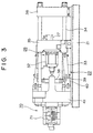
- Fig. 3 is a schematic view of a mold clamping apparatus according to the first embodiment of the invention.
- a toggle support 41 as a base plate is movable relative to the frame 21 and spaced apart from the stationary platen 36.
- Tie rods 34 connect the stationary platen 36 and the toggle support 41.
- a movable platen 35 faces on the stationary platen 36 and is movable rectilinearly along the tie rods 34.
- a stationary mold not illustrated can be attached to the stationary platen 36 on a side which faces on the movable platen 35.
- a movable mold not illustrated can be attached to the movable platen 35 on a side which faces on the stationary platen 36.
- a mold apparatus comprises the stationary mold and the movable mold.
- an ejector pin feed apparatus 26 is disposed to project ejector pins not illustrated when ejecting a molded article from the mold.
- a servomotor 32 is disposed as a drive means for the ejector pins.
- An ejector rod 27 is advanced and retracted (moved rightward and leftward in Fig. 3) along a stroke Sa by the servomotor 32.
- a toggle mechanism 22 is disposed between the movable platen 35 and the toggle support 41.
- a drive section 70 is disposed as a drive apparatus for an injection molding machine.
- a servomotor 71 is disposed as a drive means for mold clamping.
- a cross head 38 as a driven member is advanced and retracted (moved rightward and leftward in Fig. 3) so that the toggle mechanism 22 is operated and the movable platen 35 is sequentially advanced (moved rightward in Fig. 3) to thereby perform mold closing and mold clamping of the mold apparatus.
- a clamping force is a product of a thrust force generated by the servomotor 71 and toggle magnification.
- the clamping force is generated by the toggle mechanism 22.
- the thrust force generated by the servomotor 71 can be directly transmitted to the movable platen 35 for a clamping force without the toggle mechanism 22.
- the toggle mechanism 22 comprises toggle levers 39, toggle levers 40 and toggle arms 33.
- the toggle levers 39 are swingably supported relative to the cross head 38.
- the toggle levers 40 are swingably supported relative to the toggle support 41.
- the toggle levers 39 are linked with the toggle levers 40.
- the toggle arms 33 are swingably supported relative to the movable platen 35.
- the toggle levers 40 are linked with the toggle arms 33.
- the drive section 70 is explained next.
- Fig. 4 is a sectional view of the drive section 70 of the mold clamping apparatus according to the first embodiment of the invention.
- the servomotor 71 comprises a motor case 72, a rotor 77 and a stator 78 disposed inside the motor case 72.
- the motor case 72 comprises a plate-shaped first flange 74 to attach the servomotor 71 to the toggle support 41, a plate-shaped second flange 75 spaced apart from the first flange 74, and a cylindrical frame 76 disposed between the first flange 74 and the second flange 75.
- An electric motor can be served as a drive means instead of the servomotor 71.
- a hollow output shaft 80 is rotatably disposed relative to the motor case 72. Its rear end (leftward end in Fig. 4) is supported by a thrust bearing 81 while its front end (rightward end in Fig. 4) is supported by a thrust bearing 82. By these thrust bearings 81 and 82, the output shaft 80 is supported in a thrust direction and is rotatably supported in a radial direction.
- the stator 78 is fixed to the frame 76 and the rotor 77 is fixed to the output shaft 80.
- a coil 83 is mounted to the stator 78.
- Bolts not illustrated connect the first flange 74 and the second flange 75. By tightening the bolts, the frame 76 is pressed against the first flange 74 by the second flange 75.
- a spline flange 84 is fixed at the rear end (leftward end in Fig. 4) of the output shaft 80.
- a spline shaft 88 as a rotation transmission shaft and a first rotation member projects from the spline flange 84 and extends forward (rightward in Fig. 4) to the front end of the output shaft 80.
- the spline shaft 88 is as long as the output shaft 80.
- the output shaft 80 surrounds the spline shaft 88.
- a shaft 86 also projects from the spline flange 84.
- the shaft 86 is surrounded by an encoder 85 as a means for detecting rotation speed.
- the encoder 88 detects rotation speed of the spline shaft 88. The rotation speed is transmitted to a control apparatus not illustrated.
- a hole 91 is disposed at a correspondent position with the output shaft 80.
- a nut 92 is fixedly fitted into the hole 91.
- the nut 92 threadably engages with a cylindrical screw shaft 93 as a second rotation member.
- the screw shaft 93 including a screw shaft portion 93a is rotatably disposed inside the output shaft 80 and movable rectilinearly.
- the screw shaft 93 is as long as the output shaft 80 and extends throughout the output shaft 80 when the screw shaft 93 is located at the most rear position (at the most leftward position in Fig. 4).
- the screw shaft 93 surrounds the spline shaft 88. At a rear portion (leftward portion in Fig.
- a spline nut portion 96 is formed at a predetermined area along an axis of the screw shaft 93.
- An inner cylindrical surface of the spline nut portion 96 is slidably and matably engaged with an outer cylindrical surface of the spline shaft 88.
- a rotation transmission section comprises the spline shaft 88 and the spline nut portion 96.
- the cross head 38 is disposed at a front end (rightward in Fig. 4) of the screw shaft 93.
- the front end of the screw shaft 93 is rotatably supported by a pair of bearings 95 inside of a bearing housing 94 in the center of the cross head 38.
- the cross head 38 is prevented from rotating by guide bars 98.
- the drive section comprises the cross head 38, the servomotor 71, the output shaft 80, the spline flange 84, the spline shaft 88, the nut 92 and the screw shaft 93.
- a motion transformation section comprises the nut 92 and the screw shaft 93.
- the cross head 38 When the screw shaft 93 is advanced (moved rightward in Fig. 4), the cross head 38 is also advanced so that the toggle mechanism 22 illustrated in Fig. 3 extends and advances the movable platen 35, to thereby perform mold closing and mold clamping of the mold apparatus.
- the screw shaft 93 When the screw shaft 93 is retracted (moved leftward in Fig. 4), the cross head 38 is also retracted so that the toggle mechanism 22 contracts the movable platen 35, to thereby perform mold opening of the mold apparatus.
- the servomotor 71 surrounds the spline shaft 88.
- a servomotor as a drive means disposed on a lateral side of the toggle support 41 and a pulley disposed at a rear end of the spline shaft 88 can also be applied. Rotation generated by the servomotor is transmitted to the spline shaft 88 via a belt and the pulley.
- the inertia of the drive section 70 becomes small.
- the spline flange 84, the shaft 86, the spline shaft 88 and the screw shaft 93 are rotated while the output shaft 80 is rotated. With these rotating elements, the inertia of the drive section 70 is sufficiently small because the diameter of the above rotating elements is smaller than the nut 92.
- the spline nut portion 96 and the screw shaft portion 93a are not disposed in series along the screw shaft 93 in an axial direction to transmit the rotation of the output shaft 80 to the screw shaft portion 93a so that the length of the screw shaft 93 in the axial direction becomes short. Therefore, the size of the drive section 70 becomes small. Moreover, because the output shaft 80 surrounds the spline shaft 88 and the screw shaft 93 so that the output shaft 80, the spline shaft 88 and the screw shaft 93 are overlapped when the screw shaft 93 is located at the most rear position. Therefore, the size of the drive section 70 becomes small. Furthermore, sufficient room for the ejector pin feed apparatus 26 is made.
- the spline nut portion 96 is formed at the rear of the screw shaft 93.
- the spline nut potion 96 can also be formed over the entire length of the screw shaft 93.
- the spline shaft 88 and the spline nut portion 96 used as a rotation transmission section.
- a key engagement can also be used.
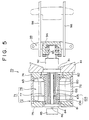
- Fig. 5 is a sectional view of a drive section of a mold clamping apparatus according to the second embodiment of the invention.
- a spline shaft 88 as a first rotation member and a rotation transmission shaft projects forward (rightward in Fig. 5) from a spline flange 84 and extends inside an output shaft 80.
- a screw shaft unit 103 as a second rotation member is rotatably and rectilinearly movably (leftward and rightward movably in Fig. 5) disposed extending inside the output shaft 80.
- the screw shaft unit 103 comprises a cylindrical screw shaft portion 105 and a spline nut 106 as an annular member.
- the spline nut 106 is attached to a rear end (left end in Fig. 5) of the screw shaft portion 105 by a means for fixing not illustrated such as bolts.
- a rotation transmission section comprises the spline shaft 88 and the spline nut 106.
- the output shaft 80 surrounds the spline shaft 88 and the screw shaft unit 103 so that the output shaft 80, the spline shaft 88 and the screw shaft unit 103 are overlapped when the screw shaft unit 103 is located at the most rear position. Therefore, the size of the drive section 70 becomes small.
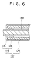
- Fig. 6 is a partial sectional view of a drive section of a mold clamping apparatus according to the third embodiment of the invention.
- a screw shaft unit 107 as a second rotation member is rotatably and rectilinearly movably disposed extending inside the output shaft.
- the screw shaft unit 107 comprises a cylindrical screw portion 105 and a spline nut 108 as an annular member.
- the spline nut 108 is attached to a rear end (left end in Fig. 6) of the screw shaft portion 105 by a means for fixing not illustrated such as bolts.
- An inner cylindrical surface of the spline nut 108 and an outer cylindrical surface of the spline shaft 88 are in slidable and matable engagement, namely, spline-engagement. Therefore, the screw shaft unit 107 is advanced and retracted upon rotation of the spline shaft 88.
- a rotation transmission section comprises the spline shaft 88 and the spline nut 108.
- the spline nut 108 comprises a cylindrical part 109 extending inside the screw shaft portion 105 and a flange part 110 which outward radially projects from a rear end of the cylindrical part 109. Because the screw shaft portion 105 and the engagement of the spline shaft 88 and the spline nut 108 are overlapped at the cylindrical part 109 in an axial direction, the length of the screw shaft unit 107 becomes short.
- the output shaft 80 surrounds the spline shaft 88 and the screw shaft unit 107 so that the output shaft 80, the spline shaft 88 and the screw shaft unit 107 are overlapped when the screw shaft unit 103 is located at the most rear position. Therefore, the size of the drive section 70 becomes small.
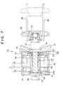
- Fig. 7 is a sectional view of a drive section of a mold clamping apparatus according to the forth embodiment of the invention.
- a spline nut 118 as a first rotation member and a rotation transmission shaft is attached to a front end (right end in Fig. 7) of the output shaft 80 by a means for fixing not illustrated such as bolts.
- a solid screw shaft 115 with a screw shaft portion 115a as a second rotation member is rotatably and rectilinearly movably (leftward and rightward movably in Fig. 7) disposed extending inside the output shaft 80.
- the screw shaft 115 extends through the spline nut 118.
- An inner cylindrical surface of the spline nut 118 and an outer cylindrical surface of the screw shaft 115 are in slidable and matable engagement, namely, spline-engagement on the screw shaft portion 115a.
- a rotation transmission section comprises the screw shaft 115 and the spline nut 118.
- the spline nut 118 comprises a cylindrical part 119 extending inside the output shaft 80 and a flange part 120 which outward radially projects from a front end of the cylindrical part 119. Because the screw shaft portion 115a and the engagement of the screw shaft 115 and the spline nut 118 are overlapped at the cylindrical part 119 in an axial direction, the length of the drive section 70 becomes short.
- the size of the drive section 70 becomes small.
- the drive section of the mold clamping apparatus is explained.
- the invention can also be applied to a drive section of an injection apparatus, a drive section of an ejector apparatus and so on.
- the invention relates to a drive apparatus for an injection molding machine comprising: (a) a drive means; (b) a rotation transmission shaft connected to the drive means and rotated by the drive means; (c) a screw shaft; (d) a nut threadably engaged with the screw shaft; and (e) a drive member disposed on the screw shaft.
Landscapes
- Engineering & Computer Science (AREA)
- Manufacturing & Machinery (AREA)
- Mechanical Engineering (AREA)
- Moulds For Moulding Plastics Or The Like (AREA)
- Injection Moulding Of Plastics Or The Like (AREA)
- Transmission Devices (AREA)
Applications Claiming Priority (2)
| Application Number | Priority Date | Filing Date | Title |
|---|---|---|---|
| JP2000050756 | 2000-02-28 | ||
| JP2000050756 | 2000-02-28 |
Publications (3)
| Publication Number | Publication Date |
|---|---|
| EP1129837A2 true EP1129837A2 (de) | 2001-09-05 |
| EP1129837A3 EP1129837A3 (de) | 2002-04-03 |
| EP1129837B1 EP1129837B1 (de) | 2005-01-19 |
Family
ID=18572508
Family Applications (1)
| Application Number | Title | Priority Date | Filing Date |
|---|---|---|---|
| EP01104913A Expired - Lifetime EP1129837B1 (de) | 2000-02-28 | 2001-02-28 | Antriebsvorrichtung für Spritzgiessmaschine |
Country Status (8)
| Country | Link |
|---|---|
| US (1) | US6916169B2 (de) |
| EP (1) | EP1129837B1 (de) |
| KR (1) | KR100408887B1 (de) |
| CN (1) | CN1226125C (de) |
| AT (1) | ATE287326T1 (de) |
| DE (1) | DE60108432T2 (de) |
| SG (1) | SG94769A1 (de) |
| TW (1) | TW504447B (de) |
Families Citing this family (8)
| Publication number | Priority date | Publication date | Assignee | Title |
|---|---|---|---|---|
| JP2004001279A (ja) * | 2002-05-31 | 2004-01-08 | Toshiba Mach Co Ltd | 射出成形機 |
| DE10230876C5 (de) * | 2002-07-09 | 2009-09-10 | Siemens Ag | Antriebsvorrichtung für eine Kunststoffverarbeitungsmaschine |
| DE102004033690A1 (de) * | 2004-07-09 | 2006-02-16 | Demag Ergotech Gmbh | Spritzgiessmaschine |
| DE102005012337B3 (de) * | 2005-03-17 | 2006-03-16 | Mannesmann Plastics Machinery Gmbh | Antriebssystem für eine Plastifiziereinheit einer Spritzgießmaschine |
| DE102006014087A1 (de) * | 2006-03-24 | 2007-09-27 | Demag Ergotech Gmbh | Spritzgießmaschine |
| JP5463007B2 (ja) * | 2008-03-18 | 2014-04-09 | 東洋機械金属株式会社 | 成形機 |
| US10449306B2 (en) | 2015-11-25 | 2019-10-22 | Medtronics Minimed, Inc. | Systems for fluid delivery with wicking membrane |
| JP6753732B2 (ja) * | 2016-08-26 | 2020-09-09 | 住友重機械工業株式会社 | 射出成形機 |
Family Cites Families (11)
| Publication number | Priority date | Publication date | Assignee | Title |
|---|---|---|---|---|
| DE2264315A1 (de) * | 1972-12-30 | 1974-07-04 | Krauss Maffei Ag | Rotations- und vorschubantriebsvorrichtung fuer eine spritzgiessmaschine |
| CA1196458A (en) * | 1981-10-08 | 1985-11-12 | Yoshihiko Yamazaki | Injection molding machine |
| JPS62128722A (ja) | 1985-11-29 | 1987-06-11 | Nissei Plastics Ind Co | 突出機構を有する型締装置 |
| JP2809347B2 (ja) | 1989-09-04 | 1998-10-08 | 住友重機械工業株式会社 | 射出成形機の射出機構 |
| JPH04113821A (ja) | 1990-09-04 | 1992-04-15 | Amada Co Ltd | 射出成形装置における射出装置 |
| JP2627235B2 (ja) | 1992-01-25 | 1997-07-02 | オークマ株式会社 | 型締駆動装置 |
| DE4344335C2 (de) | 1993-12-23 | 1996-02-01 | Krauss Maffei Ag | Einspritzaggregat für eine Spritzgießmaschine |
| US5645868A (en) | 1995-11-17 | 1997-07-08 | Cincinnati Milacron Inc. | Drive apparatus for an injection unit |
| AT404996B (de) | 1995-12-27 | 1999-04-26 | Engel Gmbh Maschbau | Verfahren zum betreiben eines antriebes |
| JP3235058B2 (ja) | 1998-06-19 | 2001-12-04 | 住友重機械工業株式会社 | 電動式型締装置 |
| JP3502545B2 (ja) * | 1998-06-26 | 2004-03-02 | 住友重機械工業株式会社 | 射出装置 |
-
2001
- 2001-02-20 TW TW090103786A patent/TW504447B/zh not_active IP Right Cessation
- 2001-02-23 SG SG200101064A patent/SG94769A1/en unknown
- 2001-02-23 US US09/790,729 patent/US6916169B2/en not_active Expired - Fee Related
- 2001-02-26 KR KR10-2001-0009543A patent/KR100408887B1/ko not_active Expired - Fee Related
- 2001-02-27 CN CNB011043423A patent/CN1226125C/zh not_active Expired - Fee Related
- 2001-02-28 AT AT01104913T patent/ATE287326T1/de not_active IP Right Cessation
- 2001-02-28 EP EP01104913A patent/EP1129837B1/de not_active Expired - Lifetime
- 2001-02-28 DE DE60108432T patent/DE60108432T2/de not_active Expired - Lifetime
Also Published As
| Publication number | Publication date |
|---|---|
| DE60108432T2 (de) | 2006-03-30 |
| EP1129837B1 (de) | 2005-01-19 |
| ATE287326T1 (de) | 2005-02-15 |
| KR20010085585A (ko) | 2001-09-07 |
| EP1129837A3 (de) | 2002-04-03 |
| US20010018079A1 (en) | 2001-08-30 |
| US6916169B2 (en) | 2005-07-12 |
| CN1311091A (zh) | 2001-09-05 |
| TW504447B (en) | 2002-10-01 |
| SG94769A1 (en) | 2003-03-18 |
| CN1226125C (zh) | 2005-11-09 |
| DE60108432D1 (de) | 2005-02-24 |
| KR100408887B1 (ko) | 2003-12-11 |
Similar Documents
| Publication | Publication Date | Title |
|---|---|---|
| US7234928B2 (en) | Injection molding machine | |
| US20090017151A1 (en) | Drive apparatus for injection molding machine, injection apparatus, and mold clamping apparatus | |
| US6364650B1 (en) | Injection apparatus with load detection between support members | |
| EP0724944B1 (de) | Auswurfvorrichtung | |
| US20070009630A1 (en) | Electric injection molding device and molding method using the same | |
| US6916169B2 (en) | Drive apparatus for injection molding machine | |
| US6796787B2 (en) | Product ejecting apparatus and method for an injection molding machine | |
| JP3335960B2 (ja) | 射出成形機におけるエジェクター装置 | |
| JP3256785B2 (ja) | 射出成形機のエジェクタ装置 | |
| JP4035123B2 (ja) | 射出成形機 | |
| JP3578997B2 (ja) | 射出成形機の駆動装置 | |
| JP3338651B2 (ja) | エジェクタ装置 | |
| JP3581088B2 (ja) | 型締駆動装置 | |
| JP2002337184A (ja) | 射出成形機の駆動源支持装置 | |
| JP3130824B2 (ja) | エジェクタ装置 | |
| JP2003145592A (ja) | エジェクタ装置 | |
| JPH10225964A (ja) | エジェクタ装置 | |
| JP2003011195A (ja) | 射出成形機の駆動装置 | |
| JP2004098703A (ja) | 電動射出成形機の射出装置及び射出成形方法 | |
| JP2001121593A (ja) | 電動式型締装置 | |
| JP2002301747A (ja) | 射出成形機の駆動装置 |
Legal Events
| Date | Code | Title | Description |
|---|---|---|---|
| PUAI | Public reference made under article 153(3) epc to a published international application that has entered the european phase |
Free format text: ORIGINAL CODE: 0009012 |
|
| AK | Designated contracting states |
Kind code of ref document: A2 Designated state(s): AT BE CH CY DE DK ES FI FR GB GR IE IT LI LU MC NL PT SE TR Kind code of ref document: A2 Designated state(s): AT CH DE FR GB IT LI |
|
| AX | Request for extension of the european patent |
Free format text: AL;LT;LV;MK;RO;SI |
|
| PUAL | Search report despatched |
Free format text: ORIGINAL CODE: 0009013 |
|
| AK | Designated contracting states |
Kind code of ref document: A3 Designated state(s): AT BE CH CY DE DK ES FI FR GB GR IE IT LI LU MC NL PT SE TR |
|
| AX | Request for extension of the european patent |
Free format text: AL;LT;LV;MK;RO;SI |
|
| 17P | Request for examination filed |
Effective date: 20021002 |
|
| AKX | Designation fees paid |
Free format text: AT CH DE FR GB IT LI |
|
| 17Q | First examination report despatched |
Effective date: 20021127 |
|
| GRAP | Despatch of communication of intention to grant a patent |
Free format text: ORIGINAL CODE: EPIDOSNIGR1 |
|
| GRAS | Grant fee paid |
Free format text: ORIGINAL CODE: EPIDOSNIGR3 |
|
| GRAA | (expected) grant |
Free format text: ORIGINAL CODE: 0009210 |
|
| AK | Designated contracting states |
Kind code of ref document: B1 Designated state(s): AT CH DE FR GB IT LI |
|
| PG25 | Lapsed in a contracting state [announced via postgrant information from national office to epo] |
Ref country code: IT Free format text: LAPSE BECAUSE OF FAILURE TO SUBMIT A TRANSLATION OF THE DESCRIPTION OR TO PAY THE FEE WITHIN THE PRESCRIBED TIME-LIMIT;WARNING: LAPSES OF ITALIAN PATENTS WITH EFFECTIVE DATE BEFORE 2007 MAY HAVE OCCURRED AT ANY TIME BEFORE 2007. THE CORRECT EFFECTIVE DATE MAY BE DIFFERENT FROM THE ONE RECORDED. Effective date: 20050119 Ref country code: CH Free format text: LAPSE BECAUSE OF FAILURE TO SUBMIT A TRANSLATION OF THE DESCRIPTION OR TO PAY THE FEE WITHIN THE PRESCRIBED TIME-LIMIT Effective date: 20050119 Ref country code: LI Free format text: LAPSE BECAUSE OF FAILURE TO SUBMIT A TRANSLATION OF THE DESCRIPTION OR TO PAY THE FEE WITHIN THE PRESCRIBED TIME-LIMIT Effective date: 20050119 Ref country code: AT Free format text: LAPSE BECAUSE OF FAILURE TO SUBMIT A TRANSLATION OF THE DESCRIPTION OR TO PAY THE FEE WITHIN THE PRESCRIBED TIME-LIMIT Effective date: 20050119 Ref country code: FR Free format text: LAPSE BECAUSE OF NON-PAYMENT OF DUE FEES Effective date: 20050119 |
|
| REG | Reference to a national code |
Ref country code: GB Ref legal event code: FG4D |
|
| REG | Reference to a national code |
Ref country code: CH Ref legal event code: EP |
|
| REG | Reference to a national code |
Ref country code: IE Ref legal event code: FG4D |
|
| REF | Corresponds to: |
Ref document number: 60108432 Country of ref document: DE Date of ref document: 20050224 Kind code of ref document: P |
|
| PG25 | Lapsed in a contracting state [announced via postgrant information from national office to epo] |
Ref country code: GB Free format text: LAPSE BECAUSE OF NON-PAYMENT OF DUE FEES Effective date: 20050419 |
|
| REG | Reference to a national code |
Ref country code: CH Ref legal event code: PL |
|
| PLBE | No opposition filed within time limit |
Free format text: ORIGINAL CODE: 0009261 |
|
| STAA | Information on the status of an ep patent application or granted ep patent |
Free format text: STATUS: NO OPPOSITION FILED WITHIN TIME LIMIT |
|
| GBPC | Gb: european patent ceased through non-payment of renewal fee |
Effective date: 20050419 |
|
| 26N | No opposition filed |
Effective date: 20051020 |
|
| EN | Fr: translation not filed | ||
| PGFP | Annual fee paid to national office [announced via postgrant information from national office to epo] |
Ref country code: DE Payment date: 20140417 Year of fee payment: 14 |
|
| REG | Reference to a national code |
Ref country code: DE Ref legal event code: R119 Ref document number: 60108432 Country of ref document: DE |
|
| PG25 | Lapsed in a contracting state [announced via postgrant information from national office to epo] |
Ref country code: DE Free format text: LAPSE BECAUSE OF NON-PAYMENT OF DUE FEES Effective date: 20150901 |