EP1129908A2 - Protection de conduite électrique - Google Patents
Protection de conduite électrique Download PDFInfo
- Publication number
- EP1129908A2 EP1129908A2 EP01104736A EP01104736A EP1129908A2 EP 1129908 A2 EP1129908 A2 EP 1129908A2 EP 01104736 A EP01104736 A EP 01104736A EP 01104736 A EP01104736 A EP 01104736A EP 1129908 A2 EP1129908 A2 EP 1129908A2
- Authority
- EP
- European Patent Office
- Prior art keywords
- protective jacket
- line
- spacers
- spacer
- protection device
- Prior art date
- Legal status (The legal status is an assumption and is not a legal conclusion. Google has not performed a legal analysis and makes no representation as to the accuracy of the status listed.)
- Withdrawn
Links
Images



Classifications
-
- B—PERFORMING OPERATIONS; TRANSPORTING
- B60—VEHICLES IN GENERAL
- B60R—VEHICLES, VEHICLE FITTINGS, OR VEHICLE PARTS, NOT OTHERWISE PROVIDED FOR
- B60R16/00—Electric or fluid circuits specially adapted for vehicles and not otherwise provided for; Arrangement of elements of electric or fluid circuits specially adapted for vehicles and not otherwise provided for
- B60R16/02—Electric or fluid circuits specially adapted for vehicles and not otherwise provided for; Arrangement of elements of electric or fluid circuits specially adapted for vehicles and not otherwise provided for electric constitutive elements
- B60R16/0207—Wire harnesses
- B60R16/0215—Protecting, fastening and routing means therefor
Definitions
- the invention relates to a line protection device for protecting Lines against animal bite, in particular for the protection of lines a Motor vehicle before marten bite.
- a line protection device with two spacers and a flat protective jacket, wherein the spacers can be attached to a line to be protected are, and wherein the protective sheath is arched to the spacers can be applied that the line of the protective jacket is circumferentially surrounded and at least along a portion of the conduit a cavity is formed between the line and the protective jacket is.
- spacers are provided that such be placed on the line so that the line is open or closed reach around.
- the protective sheath which is an open area and is not a closed sleeve or hose, is about the pre-assembled spacers wound.
- the protective jacket envelops the line with a closed circumference Line no longer accessible from the outside and thus against a connection or Bite protected by a marten. Unlike one immediate wrapping of the line is ensured by wrapping the Spacers created cavity between the line and the Protective jacket that even if the protective jacket bites the line cannot be damaged.
- the device can be mounted on the line with little effort be because the spacers, for example, laterally towards the protective line can be clipped on. In contrast, it is not as with a circumferentially closed protective sleeve or protective hose, an interim release of one end of the line is required.
- the device can also be easily connected to different line diameters or be adapted to any curve shape of the line.
- a spacer can be used for different cable diameters be used.
- To use the device at strong different cable diameters can be a set of different spacers be provided in a corresponding gradation each have a different inner diameter. Different Diameter even along a single line thus easily coped with, always a constant outer circumference the spacers and thus a constant amount of protective sheath can be provided.
- the device according to the invention is also suitable as and for protection of cuffs of handlebars and drive shafts of motor vehicles.
- the device has at least two fasteners through which the location of the to Spacers attached protective jacket fixed with respect to the line can be.
- the spacers on the line are releasably attachable, especially in that they are a clip member for comprehensive placement on the line to be protected.
- the preferably round inner diameter of a clip can be dimensioned smaller than the outer diameter of the to be protected Line, so that the spacer placed on the line is held on the line due to a clamp voltage. This makes it easier the subsequent assembly of the protective jacket.
- the clip organ can be a clip ring that is perpendicular to extends in the longitudinal direction of the line, or through a clamp sleeve be formed, which are additionally along a longitudinal section of the line extends.
- the clip member can have a radial placement slot, to allow the side to be placed on the line.
- the spacers are each at least have a spacer to which the protective jacket for production of the cavity can be created.
- the spacer preferably extends in the radial direction with respect to the line, i.e. in particular in the radial direction with respect to a clamp member Spacer.
- spokes can be used as spacers. which are connected to the clip organ, or one or more Ring discs with a central receiving opening and a radial one Attachment slot may be provided.
- the spacing organs themselves additionally extend along an axial direction of the spacer, So perpendicular to their radial direction of extension or parallel to that Longitudinal direction of the line to be protected.
- wings or ribs are provided.
- the protective sheath is either directly on the free ends of the Spokes or wings created, or the spacers are additional with an outer contact ring or an outer contact surface Mistake.
- fasteners used to attach the protective jacket to the spacers preferably fasteners used.
- fastening devices can be hooks that are already along a Long side of the protective jacket are pre-assembled and as soon as the protective jacket on the spacers, on an adjacent one Longitudinal section of the protective jacket directly or via attached to it Eyelets are hooked.
- the fastening devices can be lashing straps, for example Have cable tie straps, hook straps or hose clamps. These lashing straps are placed at the level of a spacer put on the protective sheath, reducing its size so much that the position of the protective jacket is secured.
- the protective jacket has several segments, preferably successively overlapping or immediate are arranged adjacent to each other along the line. Adjacent segments of this type of protective jacket can be connected by means of a connecting device be connected to each other. For example mutual locking, latching or hooking may be provided.
- FIG. 1a and 1b show a spacer 11. This has two C-shaped clamp rings 13, each with three radial spokes 15 an outer ring 17 are connected. The two feed rings 17 are connected via axial struts 19 so that the spacer 11 forms a cage frame.
- the clamp ring 13 and the feed ring 17 each have a circular shape and are along a common placement slot 21 in a radial Open direction.
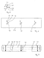
- Fig. 2 shows a protective jacket 23, which is in its unmounted state extends as a flat, rectangular surface.
- 3a and 3b is a cable tie band as a fastening device 25 shown, which has a locking cage 27 at one end and the other End has recesses 29.
- the spacer 11, the protective jacket 23 and the cable tie band 25 together form a line protection device.
- Fig. 4 To theirs Installation on a line 31 to be protected (Fig. 4) are first at least two spacers 11 under brief elastic Spread the clamp rings 13 laterally on the line 31, see above that the respective clamp ring 13 surrounds the line 31. Subsequently the protective jacket 23 is rolled around the assembled spacers 11 or wound, as indicated in Fig. 2 by the arrow 33. Finally is the circumferentially applied to the spacers 11 Protective jacket 23 fixed by means of the cable tie straps 25, the two End faces of a spacer 11 each adjacent to a cable tie band 25 is provided.
- Fig. 4 shows the line protection device mounted in this way. Because of the only indirect winding of line 31 with the protective jacket 23 this is radially spaced from the line 31, so that between the line 31 and the protective jacket 23 formed a cavity is. A mechanical action on the line 31, in particular one Damage caused by marten bite is only after penetration of the Protective jacket 23 and said cavity possible.
- the Line 31 of course along its entire length with the Protective jacket 23 is provided.
- the length of the protective jacket 23 adapted to the length of the line 31 by cutting to length.
- the spacers 11 to a safe and stable termination of the protective jacket 23 at the two ends of the line 31 to ensure the line ends immediately adjacent his.
- the width of the protective jacket 23 the circumference of the feed ring 17 of the spacers 11 is adjusted so that the two longitudinal edges of the 4 mounted protective jacket 23 exactly flush along the Adjacent to each other in the longitudinal direction of the line 31.
- the width of the protective jacket 23 can be dimensioned such that with respect to 4 results in an overlap, or that the protective jacket 23, the spacers 11 and the line 31st with multiple wraps.
- FIG. 5 shows a further spacer 35 with a C-shaped one Clamp ring 37 and three molded thereon, in the radial direction extending spokes 39. At the free end of the middle of the spokes 39 is followed by a holding member 41, for example a barb.
- the spacer 35 can be delivered with a line protection device already pre-assembled on a protective jacket 43 via the holding member 41 6, as shown in FIG. 6 for three spacers 35.
- the spacers 35 on one Line 45 (Fig. 7) have been attached, the protective jacket 43rd with its two longitudinal edges only around the spacers 35 and thus be handled around line 45.
- the protective jacket 43 with fastening devices in particular with Cable tie straps 25 according to Fig. 3a and 3b, are fixed (Fig. 7).
- a factory pre-assembly of spacers 35 on one Protective jacket 43, as shown in FIG. 6, can also be used, for example Welding of holding members 41 or spacers 35 out Metal on a protective jacket 43 made of metal.
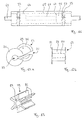
- FIGS. 8a to 8c show another example of a spacer 47, the has the shape of a hollow cylinder.
- the spacer 47 has a central receiving opening 49 in the radial direction from a Clamping sleeve 51 enclosed and only on a portion of it Is opened circumferentially to a radial mounting slot 53.
- the attachment slot 53 extends up to the outer lateral surface 55 of the spacer 47.
- the lateral surface 55 has one along its circumference Circumferential recess 57.
- 9a to 9c show a hook band 59 which has a hook at one end 61 and at the other end has a plurality of recesses 63.
- Fig. 10 shows a protective jacket 65 which has the shape of a longitudinally slit Sleeve is preformed.
- the protective jacket 65 can by means of the spacers 47 of the hook straps 59 can be mounted on a line 67 (FIG. 11). For that be initially at least two spacers 47 on line 67 clipped on so that the line 67 lies in the receiving opening 49. At this clipping the spacer 47 is briefly related to her Spread wide. Once line 67 is along the placement slot 53 is inserted into the receiving opening 49, the spacer 47 snap back into a relaxed position or under a certain one Pretension grasp the line 67.
- the protective jacket 65 with one of its two longitudinal edges are inserted into the mounting slot 53 of the spacers 47. This stabilizes the position of the protective jacket 65, so that the subsequent wrapping of the spacer 47 is also facilitated becomes.
- the protective jacket 65 applied to the spacers 47 in this way is finally fixed by means of the hook straps 59.
- the Hook straps 59 each attached to a spacer 47, and indeed along a circumferential recess 57.
- the spacer in question 47 is then compressed or compressed along its circumference, and the hook 61 is on one of the hook recesses 63 of the hook band 59 hooked.
- the line protection device assembled in this way is shown in FIG. 11.
- the two spacers 47 are exactly on the end faces of the Protective sheath 65 arranged so that the one enclosed by the protective sheath 65 Cavity is also at least partially closed laterally.
- Each spacer 47 is assigned exactly one hook band 59, and indeed along the circumferential recess 57. As a result, the hook bands 59 secured against inadvertent slipping sideways.
- FIGS. 12a and 12b show a further spacer 69 with two Ring washers 71 on the two end faces, which have a hollow cylinder 73 are connected.
- the spacer 69 has a placement slot 75, which extends radially into a central receiving opening 77 enough.
- the two washers 71 can, similar to the circumferential recess 57, a fastening device lashed to the spacer 69 against inadvertent slipping sideways to back up.
- FIG. 13 shows a further example of a spacer 79 as spacers six wings 81, which extend in the radial direction extend.
- the wings 81 on a longitudinally slotted clamp sleeve 83 additionally along an axial direction.
- FIG. 14a and 14b show a further example of a protective jacket 85 which which is formed from a wire mesh.
- a protective jacket 85 which is formed from a wire mesh.
- three hooks 87 are attached.
- Three corresponding eyelets 89 are incorporated in the longitudinal edge.
- the hooks 87 in the associated Eyelets 89 attached.
- the protective jacket 85 as a wire mesh can also have a perforated plate or a grid.
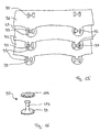
- Neighboring protective jacket segments 91 are relative to one another in this way arranged that two pairs of connection openings 95 at least partly lying on top of each other.
- the protective jacket segments 91 are fixed to each other by locking elements 97 in the aligned Connection openings 95 are introduced.
- the protective jacket segments 91 can already be pre-assembled in the factory in the manner shown in FIG be, or the connection of several protective jacket segments 91 to each other takes place - depending on the length of the line to be protected - only during final assembly on site.
- FIG. 16 shows a double push button as an example of a locking member 97.
- This has a locking base plate as an insertion part 99 with an axial insertion pin 101, and as a mounting part Locking counter plate 103.
- the insertion pin 101 is passed through from one side the aligned connection openings 95 and the locking counterplate 103 is on the other side at the free end of the insertion pin 101 locked. It is important that the locking base plate 99 and the locking counter plate 103 are sufficiently large to prevent accidental axial escape of the double push button 97 from the To prevent connection openings 95.
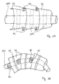
- the line 105 is previously with spacers 107 has been provided with a trapezoidal cross-section own and otherwise for example according to the spacers 47 11 can correspond.
- the protective jacket segments 91 have essentially wrapping the line 105 in the form of a truncated cone surface, and they overlap like scales.
- the protective jacket segments 91 are mounted on the spacers 107 preferably fixed via fastening devices, wherein for example the cable tie band 25 according to FIG. 7 or the hook band 59 according to FIG. 11 can be used.
- the explained subdivision of the Protective jacket in segments 91 has the advantage that the protective jacket on curved lines can be adapted in a simple manner: FIG. 18 shows a curved line 105 that of three protective jacket segments 91 is wrapped.
- connection openings 95 of the segments 91 according to FIG. 15 and 17 a two-dimensional course, namely an H shape.
- buttons 97 shown can be used as a closure member and counter-locking element also simple push buttons can be used, whose base plate 99 is firmly connected to a segment 91.
- connection openings 95 are not based two- or one-dimensional connection openings 95 must be made. If the connection openings do not move the segments 91 allow, a sufficient possibility of adapting the Protective jacket on curved lines are created that the segments 91 to be connected with joints or hinges are provided. In particular, connection processes the type 93 shown hinge-like elastically bendable his.
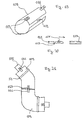
- Fig. 19 shows a protective jacket segment 109. To connect this segment 109 with adjacent, immediately adjacent segments on the end faces of the segment 109 two closure members 111 and two, respectively Counter-closure elements 113 are provided.
- the closure member 111 has a locking lug 115, which is designed as a locking cage Closure member 113 is introduced.
- the closure member 111 is also due to a central taper 117 designed to be flexibly pivotable upwards and downwards.
- the Closure member 111 can thus act as a hinge to different Diameter of the cable to be protected or the spacer used to be able to overcome and / or to adapt to to enable a curved course of the line to be protected.
- FIG. 21 shows the possibility of protective jacket segments 109 to be provided which are pre-curved in terms of their axial direction in order to enable or simplify the adaptation to curved lines 105.
- spacers are not shown in FIG. 21 and preferably fastening devices 59 are provided.
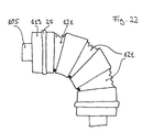
- FIG. 22 shows a protective jacket 119 which has a plurality of circumferential notches 121 has an adaptation of the protective jacket 119 to different allow curved lines 115.
- the spacers 11, 35, 47, 69, 79, 107, the fasteners 25, 59, 87, 89 and the Protective sheaths 23, 43, 65, 85, 91, 109, 119 made of metal or a heat and cold-resistant, bite-resistant and preferably elastic plastic can exist.
Landscapes
- Engineering & Computer Science (AREA)
- Mechanical Engineering (AREA)
- Clamps And Clips (AREA)
- Details Of Indoor Wiring (AREA)
Applications Claiming Priority (2)
| Application Number | Priority Date | Filing Date | Title |
|---|---|---|---|
| DE2000109491 DE10009491A1 (de) | 2000-02-29 | 2000-02-29 | Leitungsschutzvorrichtung |
| DE10009491 | 2000-02-29 |
Publications (2)
| Publication Number | Publication Date |
|---|---|
| EP1129908A2 true EP1129908A2 (fr) | 2001-09-05 |
| EP1129908A3 EP1129908A3 (fr) | 2003-07-16 |
Family
ID=7632800
Family Applications (1)
| Application Number | Title | Priority Date | Filing Date |
|---|---|---|---|
| EP01104736A Withdrawn EP1129908A3 (fr) | 2000-02-29 | 2001-02-26 | Protection de conduite électrique |
Country Status (2)
| Country | Link |
|---|---|
| EP (1) | EP1129908A3 (fr) |
| DE (1) | DE10009491A1 (fr) |
Cited By (1)
| Publication number | Priority date | Publication date | Assignee | Title |
|---|---|---|---|---|
| USD1008195S1 (en) | 2022-07-20 | 2023-12-19 | Cable Shield, LLC | Cable protector |
Families Citing this family (3)
| Publication number | Priority date | Publication date | Assignee | Title |
|---|---|---|---|---|
| DE202010014958U1 (de) | 2010-10-30 | 2011-02-24 | Berensmeier, Marc Andre | Energieautarker elektronischer Marderschreck |
| DE102011122565A1 (de) | 2011-12-23 | 2013-06-27 | Volkswagen Aktiengesellschaft | Vorrichtung und Verfahren zum Vertreiben von Mardern |
| CN113895372B (zh) * | 2021-11-11 | 2023-03-21 | 盐城市华悦汽车部件有限公司 | 一种汽车高压线束总成 |
Family Cites Families (4)
| Publication number | Priority date | Publication date | Assignee | Title |
|---|---|---|---|---|
| DE3538706C1 (en) * | 1985-10-31 | 1987-02-26 | Daimler Benz Ag | Covering for motor vehicle parts to prevent damage caused by gnawing or scratching by animals |
| DE9308557U1 (de) * | 1993-06-08 | 1993-08-12 | Böllhoff & Co GmbH & Co KG, 33649 Bielefeld | Schutzumhüllung gegen Tierverbiß |
| DE9413888U1 (de) * | 1993-08-31 | 1994-11-03 | Bürgi & Co., Steckborn | Vorrichtung zur Verhinderung von Bißschäden durch Marder und andere Nagetiere an Gummi- und Kunststoffteilen innerhalb und außerhalb der Karosserie von Fahrzeugen |
| DE29510461U1 (de) * | 1995-06-28 | 1995-09-07 | Schlemmer - UNICOR Rohrproduktions GmbH, 97437 Haßfurt | Schutzrohr gegen Marderverbiß |
-
2000
- 2000-02-29 DE DE2000109491 patent/DE10009491A1/de not_active Withdrawn
-
2001
- 2001-02-26 EP EP01104736A patent/EP1129908A3/fr not_active Withdrawn
Cited By (1)
| Publication number | Priority date | Publication date | Assignee | Title |
|---|---|---|---|---|
| USD1008195S1 (en) | 2022-07-20 | 2023-12-19 | Cable Shield, LLC | Cable protector |
Also Published As
| Publication number | Publication date |
|---|---|
| DE10009491A1 (de) | 2001-08-30 |
| EP1129908A3 (fr) | 2003-07-16 |
Similar Documents
| Publication | Publication Date | Title |
|---|---|---|
| DE3840880C2 (de) | Leitende Kabelhülle | |
| DE3633486C1 (de) | Schlauchklemme | |
| DE2923766C2 (fr) | ||
| DE60213528T2 (de) | Kabelbinder | |
| AT398460B (de) | Offene klemmenanordnung | |
| DE19500161C2 (de) | Einstellbare Klemmvorrichtung | |
| DE102012023735A1 (de) | Verfahren zum Verlängern von Eigenhaarsträhnen | |
| DE2813484A1 (de) | Kabelband | |
| DE2009714B2 (de) | Geschlitzte Büchse aus elastischem Material | |
| DE3343927A1 (de) | Ohrlose klemmstruktur | |
| EP2087807A2 (fr) | Bigoudi doté de substances thermochromes | |
| DE1946367B2 (de) | Bandklemme | |
| EP2163408A1 (fr) | Chaîne de protection de glissement | |
| DE2901383C3 (de) | Bandspule | |
| DE202018107343U1 (de) | Zugfederanordnung | |
| DE2133801A1 (de) | Reifenkette | |
| DE102008020894A1 (de) | Befestigungsanordnung für die Anbringung eines Kabels oder Kabelbündels an einem Abschnitt einer Karosserie eines Automobils bzw. Halteelement aus Kunststoff | |
| DE602004008286T2 (de) | Muffenband | |
| DE102016115536A1 (de) | Sicherungskralle | |
| EP0990811A1 (fr) | Dispositif de soufflet préassemblé pour couvrir des arbres articulés | |
| DD142018A5 (de) | Schneegleitschutz-vorrichtung fuer kraftfahrzeuge | |
| DE102012110659B4 (de) | Zwischenstütze, Sicherungssysteme und Verfahren zum Anbringen einer Zwischenstütze | |
| DE2253813A1 (de) | Reifenkette | |
| DE10009491A1 (de) | Leitungsschutzvorrichtung | |
| DE2911897A1 (de) | Rohrschelle |
Legal Events
| Date | Code | Title | Description |
|---|---|---|---|
| PUAI | Public reference made under article 153(3) epc to a published international application that has entered the european phase |
Free format text: ORIGINAL CODE: 0009012 |
|
| AK | Designated contracting states |
Kind code of ref document: A2 Designated state(s): AT BE CH CY DE DK ES FI FR GB GR IE IT LI LU MC NL PT SE TR |
|
| AX | Request for extension of the european patent |
Free format text: AL;LT;LV;MK;RO;SI |
|
| PUAL | Search report despatched |
Free format text: ORIGINAL CODE: 0009013 |
|
| AK | Designated contracting states |
Designated state(s): AT BE CH CY DE DK ES FI FR GB GR IE IT LI LU MC NL PT SE TR |
|
| AX | Request for extension of the european patent |
Extension state: AL LT LV MK RO SI |
|
| RIC1 | Information provided on ipc code assigned before grant |
Ipc: 7B 60R 27/00 A |
|
| AKX | Designation fees paid | ||
| REG | Reference to a national code |
Ref country code: DE Ref legal event code: 8566 |
|
| STAA | Information on the status of an ep patent application or granted ep patent |
Free format text: STATUS: THE APPLICATION IS DEEMED TO BE WITHDRAWN |
|
| 18D | Application deemed to be withdrawn |
Effective date: 20040117 |