EP1129921A2 - Dispositif d'accouplement pour véhicules ferroviaires - Google Patents
Dispositif d'accouplement pour véhicules ferroviaires Download PDFInfo
- Publication number
- EP1129921A2 EP1129921A2 EP01810123A EP01810123A EP1129921A2 EP 1129921 A2 EP1129921 A2 EP 1129921A2 EP 01810123 A EP01810123 A EP 01810123A EP 01810123 A EP01810123 A EP 01810123A EP 1129921 A2 EP1129921 A2 EP 1129921A2
- Authority
- EP
- European Patent Office
- Prior art keywords
- support arm
- arm
- coupling device
- traction means
- vehicle
- Prior art date
- Legal status (The legal status is an assumption and is not a legal conclusion. Google has not performed a legal analysis and makes no representation as to the accuracy of the status listed.)
- Granted
Links
- 238000010168 coupling process Methods 0.000 title claims abstract description 69
- 238000005859 coupling reaction Methods 0.000 title claims abstract description 69
- 230000008878 coupling Effects 0.000 title claims abstract description 68
- 230000007423 decrease Effects 0.000 claims description 2
- 238000004519 manufacturing process Methods 0.000 description 2
- 238000000418 atomic force spectrum Methods 0.000 description 1
- 230000001419 dependent effect Effects 0.000 description 1
- 238000007689 inspection Methods 0.000 description 1
- 238000012423 maintenance Methods 0.000 description 1
- 238000004904 shortening Methods 0.000 description 1
Images




Classifications
-
- B—PERFORMING OPERATIONS; TRANSPORTING
- B61—RAILWAYS
- B61G—COUPLINGS; DRAUGHT AND BUFFING APPLIANCES
- B61G7/00—Details or accessories
- B61G7/10—Mounting of the couplings on the vehicle
- B61G7/12—Adjustable coupling bars, e.g. for centralisation purposes
Definitions
- the invention relates to a coupling device for rail vehicles according to the Preamble of claim 1.
- Coupling devices of this type can be used on a wide variety of rail vehicles be used. So that the coupling device in the unloaded, not coupled Assumes a ready-to-couple basic position, in which it at least is aligned approximately parallel to the longitudinal central axis of the rail vehicle, centering devices must be provided. The centering devices must allow pivoting of the support arm so that the coupling device in engaged state can be deflected laterally when driving through curves can.
- a generally known centering device for coupling devices The type in question has two roller levers provided with rollers, which are articulated are supported on the vehicle and biased against each other via a tension spring are.
- the centering device In the end area on the vehicle side, the centering device has Support arm arranged cams, which work together with the roller levers are determined by the support arm through the abutting on the cams Roles is aligned.
- the centering device can be used for certain coupling devices be designed so that the coupling device is ready for operation Active position relative to the longitudinal central axis of the rail vehicle by a few Degree is deflected. This is particularly useful if the coupling head has a bevel along which it automatically when engaging moves to the end coupling position.
- the object of the invention is now one in the preamble of claim 1 to design defined coupling device for rail vehicles such that it is simple to build and inexpensive to implement, it is largely wear-free is and also in relation to twists of the support arm around it Longitudinal central axis is insensitive.
- Preferred embodiments of the coupling device are in the dependent claims 2 to 10 circumscribed.
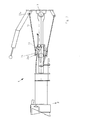
- the basic structure of the coupling device is summarized on the basis of FIG explained in more detail with a first embodiment of the centering device. Since the basic structure of generic coupling devices is known, many areas of the coupling device are only shown schematically. Essentially is therefore only relevant to those according to the invention or important components for general understanding.
- the coupling device has a support arm 1 formed by two articulated arms on, the rear articulated arm facing the rail vehicle having the reference symbol 2 carries and the front articulated arm facing away from the rail vehicle the reference number 3 is provided.
- the rear articulated arm 2 is via a bearing 7 rotatably supported on the rail vehicle, while the two articulated arms 2, 3 are connected to each other via an articulated joint 8.
- the actual coupling head 4 is arranged at the front articulated arm 3 .
- the locking mechanism 11 has a rotatably arranged locking lever 12, which is held in the locked position by a spring 13. To twist of the locking lever 12, this is connected to a pull rope 14 which ends with a handle 15 for manually unlocking the locking mechanism 11 is provided.
- a centering device 17 is provided.
- This has two on one Side of the support arm 1 arranged traction means 18, 19 on the one hand on the vehicle and on the other hand are fixed to the support arm 1.
- a bracket 21, 22 is provided, which with a deflectable and provided by a spring 25, 26 cantilever arm 23, 24 is.
- the spring 25, 26 pulls the respective extension arm 23, 24 inwards a stop 30, 31 on which the cantilever arm 23, 24 in its unloaded At rest.
- a support element 32, 33 arranged on the side of the support arm 1 is provided.
- the elements mentioned are coordinated so that the between the vehicle-side fixing point 32a, 33a of the traction means 18, 19 and the support arm side Fixing point 23a, 24a of the traction means 18, 19 extending line of force in which Basic position of the support arm 1, on the outside facing away from the support arm 1 the axis of rotation 27, 28 of the respective cantilever arm 23, 24, so that the respective Cantilever arm 23, 24 under the action of the traction means 18, 19 from the stop 30, 31 can be lifted and pivoted outwards.
- the traction devices 18, 19 are arranged so that they form an angle of approximately 5 to 15 degrees with the Include the longitudinal center axis 9 of the support arm 1. This design ensures that the support arm 1 is ready for coupling in the unloaded state Basic position is maintained.
- the coupling device is in the functional basic position with respect to the longitudinal central axis 10 of the rail vehicle deflects by approx. 2.5 °, so that the coupling head 4 turns when engaging automatically along its bevel at the top, relative to the opposite one Coupling head, can move into the end coupling position.
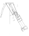
- FIG. 2 shows the coupling device according to FIG. 1 in a first phase with the side Swiveling in one direction. From these representations it can be seen that the arm 24 opposite the pivoting direction P under the action of the active traction means 19 is deflected. Because the between the two attachment points 24a, 33a of the active traction means 19 extending line of force at the beginning the pivoting is very close to the pivot point 28 of the cantilever arm 24, is the force required to pivot the support arm 1 at the first moment relatively large. However, with increasing pivoting of the support arm 1 (FIG. 3) the distance between the line of force of the active traction means 19 and the fulcrum 28 of the cantilever arm 24 and the force to be applied accordingly.
- Fig. 4 shows the coupling device according to Fig. 1 when pivoting in the other Direction P1.
- the other again the pivot direction P1 opposite cantilever arm 23, deflected under the action of the traction means 18 becomes.
- the centering forces acting on the support arm 1 from the centering device are depending on various factors.
- the coupling device can by varying the angle between the traction means 18, 19 and the longitudinal center axis 9 of the coupling device the arrangement and configuration of the arms 21, 22 and the arms 23, 24, by the bias and spring rate of the springs 25, 26 and by the attachment points the traction means 18, 19, in particular by the course of the force line between the vehicle-side fixing points 32a, 33a of the traction means 18, 19 and the support arm-side fixing points 23a, 24a of the traction means 18, 19, in particular by the Distance of the lines of force from the axis of rotation 27, 28 of the respective cantilever arm 23, 24, the centering forces and / or the force curve can be varied.
- the one on the left seen from the rail vehicle takes over Traction means 18, however, perform another task by using the two articulated arms 2, 3 imposes a certain trajectory when buckling.
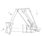
- 5 is the Coupling device shown in a first phase when the support arm 1 buckles. Bend around the support arm 1 and the coupling device into a compact, To be able to transfer the retracted state, the locking mechanism must first 11 can be unlocked. By pulling the handle 15 Locking lever 12 rotated against the force of the spring 13 via the pull cable 14, so that the support arm can be buckled at the articulated joint 8. This will the coupling head 4 is pivoted manually in the direction of arrow P2 (FIG. 6).
- Fig. 7 shows the coupling device in a fully buckled state.
- the Coupling head 4 is received in a holder 35 and fixed therein.
- the coupling device with an alternative embodiment is a Centering device 37 shown, only half of the centering device 37 is explained in more detail.
- a guide rod 39 is provided.
- an arcuate member 40 which is rotatable on the cantilever arm 23 is supported.
- the guide rod 39 is arcuate in a receptacle Guided element 40 and provided with a stop (not shown), which causes the guide rod 39 to pivot when the Support arm 1 can move freely through the receptacle to the left due to the Shortening the distance between the attachment point 32a of the guide means 39 on the rail vehicle and the recording and therefore inactive while moving the stop of the guide rod 39 after pivoting the support arm 1 after puts on the right on the recording and the boom 23 in the previously described Rotated against the bias of the spring 25 about the axis of rotation 27, so that the support arm 1 pivots to the right without any significant influence can be.
- the Swivel path can be selected so that the coupling head 4 a predetermined does not leave the lateral area by the coupling head 4 when swiveling for example, never to protrude beyond the lateral contour of the rail vehicle is coming.
- the rest position of the coupling device or its space requirements can be varied depending on the lateral deflection of the rear articulated arm 3, the rest position of the coupling device or its space requirements can be varied.
Landscapes
- Engineering & Computer Science (AREA)
- Mechanical Engineering (AREA)
- Platform Screen Doors And Railroad Systems (AREA)
- Fittings On The Vehicle Exterior For Carrying Loads, And Devices For Holding Or Mounting Articles (AREA)
- Lift-Guide Devices, And Elevator Ropes And Cables (AREA)
Applications Claiming Priority (2)
| Application Number | Priority Date | Filing Date | Title |
|---|---|---|---|
| DE10010063A DE10010063A1 (de) | 2000-03-02 | 2000-03-02 | Kupplungsvorrichtung für Schienenfahrzeuge |
| DE10010063 | 2000-03-02 |
Publications (3)
| Publication Number | Publication Date |
|---|---|
| EP1129921A2 true EP1129921A2 (fr) | 2001-09-05 |
| EP1129921A3 EP1129921A3 (fr) | 2002-10-09 |
| EP1129921B1 EP1129921B1 (fr) | 2005-01-05 |
Family
ID=7633167
Family Applications (1)
| Application Number | Title | Priority Date | Filing Date |
|---|---|---|---|
| EP01810123A Expired - Lifetime EP1129921B1 (fr) | 2000-03-02 | 2001-02-07 | Dispositif d'accouplement pour véhicules ferroviaires |
Country Status (3)
| Country | Link |
|---|---|
| EP (1) | EP1129921B1 (fr) |
| AT (1) | ATE286469T1 (fr) |
| DE (2) | DE10010063A1 (fr) |
Cited By (1)
| Publication number | Priority date | Publication date | Assignee | Title |
|---|---|---|---|---|
| CN112896224A (zh) * | 2021-02-04 | 2021-06-04 | 中车青岛四方车辆研究所有限公司 | 车钩及其锁定方法 |
Family Cites Families (4)
| Publication number | Priority date | Publication date | Assignee | Title |
|---|---|---|---|---|
| US710929A (en) * | 1902-03-12 | 1902-10-07 | Mcconway & Torley Co | Draft and buffing mechanism for cars. |
| US1346545A (en) * | 1920-03-30 | 1920-07-13 | Mcconway & Torley Co | Draft appliance for railway-vehicles |
| DE1005548B (de) * | 1954-04-28 | 1957-04-04 | Bergische Stahlindustrie | Aufhaengung fuer Mittelkupplungen, insbesondere von Schienenfahrzeugen mit federbetaetigter Mittelstelleinrichtung |
| DE1052440B (de) * | 1957-02-15 | 1959-03-12 | Scharfenbergkupplung Gmbh | Mittelpufferkupplung mit in Querrichtung pendelnd aufgehaengter Federabstuetzung |
-
2000
- 2000-03-02 DE DE10010063A patent/DE10010063A1/de not_active Ceased
-
2001
- 2001-02-07 EP EP01810123A patent/EP1129921B1/fr not_active Expired - Lifetime
- 2001-02-07 DE DE50105003T patent/DE50105003D1/de not_active Expired - Fee Related
- 2001-02-07 AT AT01810123T patent/ATE286469T1/de not_active IP Right Cessation
Non-Patent Citations (1)
| Title |
|---|
| None |
Cited By (2)
| Publication number | Priority date | Publication date | Assignee | Title |
|---|---|---|---|---|
| CN112896224A (zh) * | 2021-02-04 | 2021-06-04 | 中车青岛四方车辆研究所有限公司 | 车钩及其锁定方法 |
| CN112896224B (zh) * | 2021-02-04 | 2022-04-12 | 中车青岛四方车辆研究所有限公司 | 车钩及其锁定方法 |
Also Published As
| Publication number | Publication date |
|---|---|
| DE50105003D1 (de) | 2005-02-10 |
| ATE286469T1 (de) | 2005-01-15 |
| EP1129921A3 (fr) | 2002-10-09 |
| EP1129921B1 (fr) | 2005-01-05 |
| DE10010063A1 (de) | 2001-09-13 |
Similar Documents
| Publication | Publication Date | Title |
|---|---|---|
| AT398149B (de) | Seitenstrebe für die unterlenker einer dreipunktanbauvorrichtung | |
| EP2847012B1 (fr) | Fixation d'essieu pour un essieu suspendu de véhicule | |
| DE4447860C2 (de) | Schleppfahrzeug zum Manövrieren von Flugzeugen | |
| EP1884410A2 (fr) | Porte-charge | |
| DE8306381U1 (de) | Reinigungsvorrichtung zur innenreinigung von tanks od. dgl. | |
| EP1044869A2 (fr) | Plate-forme de chargement pour véhicule utilitaire | |
| EP1129920B1 (fr) | Barre d'attelage repliable pour véhicules ferroviaires | |
| EP1961691B1 (fr) | Appareil de transbordement | |
| EP0326570A1 (fr) | Barre d'attelage reglable en hauteur pour remorque de vehicule. | |
| DE1580908B2 (de) | Gehaenge fuer umlauf-seilschwebebahnen | |
| DE3407526C2 (fr) | ||
| DE69427033T2 (de) | Vorrichtung zum ausschieben und auslagern von einem horizontalen ausleger | |
| DE69903286T2 (de) | Werkzeug zum spannen von drähten | |
| DE2433958C2 (de) | Selbstnivellierende Ausgabevorrichtung | |
| EP1129921B1 (fr) | Dispositif d'accouplement pour véhicules ferroviaires | |
| EP3800299A1 (fr) | Équipement, en particulier chargeur sur roues | |
| DE10209387C1 (de) | Scherenhubtisch | |
| DE19528308A1 (de) | Fahrzeug, insbesondere Personenkraftwagen | |
| EP3078545B1 (fr) | Tendeur de sangle | |
| DE102019202575B3 (de) | Mastanbauspitze für einen Mobilkran und Mobilkran | |
| DE19918116C1 (de) | Fördermittel für ein Hängefördersystem | |
| DE19512384C2 (de) | Mittelpufferkupplung für Schienenfahrzeuge | |
| DE102024125519B3 (de) | Schlitten und öffenbares Seitenplanenwandsystem | |
| DE2300750A1 (de) | Gerueststuetze | |
| DE2710234C2 (de) | Eigengewichts-Klemmkupplung für ein Gehänge einer Umlauf-Seilschwebebahn |
Legal Events
| Date | Code | Title | Description |
|---|---|---|---|
| PUAI | Public reference made under article 153(3) epc to a published international application that has entered the european phase |
Free format text: ORIGINAL CODE: 0009012 |
|
| AK | Designated contracting states |
Kind code of ref document: A2 Designated state(s): AT BE CH CY DE DK ES FI FR GB GR IE IT LI LU MC NL PT SE TR |
|
| AX | Request for extension of the european patent |
Free format text: AL;LT;LV;MK;RO;SI |
|
| PUAL | Search report despatched |
Free format text: ORIGINAL CODE: 0009013 |
|
| AK | Designated contracting states |
Kind code of ref document: A3 Designated state(s): AT BE CH CY DE DK ES FI FR GB GR IE IT LI LU MC NL PT SE TR |
|
| AX | Request for extension of the european patent |
Free format text: AL;LT;LV;MK;RO;SI |
|
| 17P | Request for examination filed |
Effective date: 20021127 |
|
| 17Q | First examination report despatched |
Effective date: 20030508 |
|
| AKX | Designation fees paid |
Designated state(s): AT BE CH CY DE DK ES FI FR GB GR IE IT LI LU MC NL PT SE TR |
|
| GRAP | Despatch of communication of intention to grant a patent |
Free format text: ORIGINAL CODE: EPIDOSNIGR1 |
|
| GRAS | Grant fee paid |
Free format text: ORIGINAL CODE: EPIDOSNIGR3 |
|
| GRAA | (expected) grant |
Free format text: ORIGINAL CODE: 0009210 |
|
| AK | Designated contracting states |
Kind code of ref document: B1 Designated state(s): AT BE CH CY DE DK ES FI FR GB GR IE IT LI LU MC NL PT SE TR |
|
| PG25 | Lapsed in a contracting state [announced via postgrant information from national office to epo] |
Ref country code: IE Free format text: LAPSE BECAUSE OF FAILURE TO SUBMIT A TRANSLATION OF THE DESCRIPTION OR TO PAY THE FEE WITHIN THE PRESCRIBED TIME-LIMIT Effective date: 20050105 Ref country code: TR Free format text: LAPSE BECAUSE OF FAILURE TO SUBMIT A TRANSLATION OF THE DESCRIPTION OR TO PAY THE FEE WITHIN THE PRESCRIBED TIME-LIMIT Effective date: 20050105 Ref country code: NL Free format text: LAPSE BECAUSE OF FAILURE TO SUBMIT A TRANSLATION OF THE DESCRIPTION OR TO PAY THE FEE WITHIN THE PRESCRIBED TIME-LIMIT Effective date: 20050105 Ref country code: GB Free format text: LAPSE BECAUSE OF FAILURE TO SUBMIT A TRANSLATION OF THE DESCRIPTION OR TO PAY THE FEE WITHIN THE PRESCRIBED TIME-LIMIT Effective date: 20050105 |
|
| REG | Reference to a national code |
Ref country code: GB Ref legal event code: FG4D Free format text: NOT ENGLISH |
|
| REG | Reference to a national code |
Ref country code: CH Ref legal event code: NV Representative=s name: ROTTMANN, ZIMMERMANN + PARTNER AG Ref country code: CH Ref legal event code: EP |
|
| PG25 | Lapsed in a contracting state [announced via postgrant information from national office to epo] |
Ref country code: LU Free format text: LAPSE BECAUSE OF NON-PAYMENT OF DUE FEES Effective date: 20050207 Ref country code: CY Free format text: LAPSE BECAUSE OF FAILURE TO SUBMIT A TRANSLATION OF THE DESCRIPTION OR TO PAY THE FEE WITHIN THE PRESCRIBED TIME-LIMIT Effective date: 20050207 |
|
| REG | Reference to a national code |
Ref country code: IE Ref legal event code: FG4D Free format text: GERMAN |
|
| REF | Corresponds to: |
Ref document number: 50105003 Country of ref document: DE Date of ref document: 20050210 Kind code of ref document: P |
|
| PG25 | Lapsed in a contracting state [announced via postgrant information from national office to epo] |
Ref country code: MC Free format text: LAPSE BECAUSE OF NON-PAYMENT OF DUE FEES Effective date: 20050228 |
|
| PG25 | Lapsed in a contracting state [announced via postgrant information from national office to epo] |
Ref country code: DK Free format text: LAPSE BECAUSE OF FAILURE TO SUBMIT A TRANSLATION OF THE DESCRIPTION OR TO PAY THE FEE WITHIN THE PRESCRIBED TIME-LIMIT Effective date: 20050405 Ref country code: GR Free format text: LAPSE BECAUSE OF FAILURE TO SUBMIT A TRANSLATION OF THE DESCRIPTION OR TO PAY THE FEE WITHIN THE PRESCRIBED TIME-LIMIT Effective date: 20050405 |
|
| PG25 | Lapsed in a contracting state [announced via postgrant information from national office to epo] |
Ref country code: ES Free format text: LAPSE BECAUSE OF FAILURE TO SUBMIT A TRANSLATION OF THE DESCRIPTION OR TO PAY THE FEE WITHIN THE PRESCRIBED TIME-LIMIT Effective date: 20050416 |
|
| REG | Reference to a national code |
Ref country code: SE Ref legal event code: TRGR |
|
| NLV1 | Nl: lapsed or annulled due to failure to fulfill the requirements of art. 29p and 29m of the patents act | ||
| GBV | Gb: ep patent (uk) treated as always having been void in accordance with gb section 77(7)/1977 [no translation filed] |
Effective date: 20050105 |
|
| REG | Reference to a national code |
Ref country code: IE Ref legal event code: FD4D |
|
| ET | Fr: translation filed | ||
| PLBE | No opposition filed within time limit |
Free format text: ORIGINAL CODE: 0009261 |
|
| STAA | Information on the status of an ep patent application or granted ep patent |
Free format text: STATUS: NO OPPOSITION FILED WITHIN TIME LIMIT |
|
| 26N | No opposition filed |
Effective date: 20051006 |
|
| REG | Reference to a national code |
Ref country code: GB Ref legal event code: FG4D Free format text: NOT ENGLISH |
|
| PGFP | Annual fee paid to national office [announced via postgrant information from national office to epo] |
Ref country code: IT Payment date: 20060228 Year of fee payment: 6 |
|
| PG25 | Lapsed in a contracting state [announced via postgrant information from national office to epo] |
Ref country code: PT Free format text: LAPSE BECAUSE OF NON-PAYMENT OF DUE FEES Effective date: 20050605 |
|
| PGFP | Annual fee paid to national office [announced via postgrant information from national office to epo] |
Ref country code: CH Payment date: 20080118 Year of fee payment: 8 |
|
| PGFP | Annual fee paid to national office [announced via postgrant information from national office to epo] |
Ref country code: DE Payment date: 20080118 Year of fee payment: 8 Ref country code: FI Payment date: 20080117 Year of fee payment: 8 Ref country code: SE Payment date: 20080121 Year of fee payment: 8 |
|
| PGFP | Annual fee paid to national office [announced via postgrant information from national office to epo] |
Ref country code: AT Payment date: 20080110 Year of fee payment: 8 |
|
| PGFP | Annual fee paid to national office [announced via postgrant information from national office to epo] |
Ref country code: FR Payment date: 20080114 Year of fee payment: 8 |
|
| PGFP | Annual fee paid to national office [announced via postgrant information from national office to epo] |
Ref country code: BE Payment date: 20080208 Year of fee payment: 8 |
|
| BERE | Be: lapsed |
Owner name: *SCHWAB VERKEHRSTECHNIK A.G. Effective date: 20090228 |
|
| PG25 | Lapsed in a contracting state [announced via postgrant information from national office to epo] |
Ref country code: IT Free format text: LAPSE BECAUSE OF NON-PAYMENT OF DUE FEES Effective date: 20070207 |
|
| REG | Reference to a national code |
Ref country code: CH Ref legal event code: PL |
|
| EUG | Se: european patent has lapsed | ||
| PG25 | Lapsed in a contracting state [announced via postgrant information from national office to epo] |
Ref country code: FI Free format text: LAPSE BECAUSE OF NON-PAYMENT OF DUE FEES Effective date: 20090207 Ref country code: LI Free format text: LAPSE BECAUSE OF NON-PAYMENT OF DUE FEES Effective date: 20090228 Ref country code: CH Free format text: LAPSE BECAUSE OF NON-PAYMENT OF DUE FEES Effective date: 20090228 Ref country code: AT Free format text: LAPSE BECAUSE OF NON-PAYMENT OF DUE FEES Effective date: 20090207 |
|
| REG | Reference to a national code |
Ref country code: FR Ref legal event code: ST Effective date: 20091030 |
|
| PG25 | Lapsed in a contracting state [announced via postgrant information from national office to epo] |
Ref country code: DE Free format text: LAPSE BECAUSE OF NON-PAYMENT OF DUE FEES Effective date: 20090901 |
|
| PG25 | Lapsed in a contracting state [announced via postgrant information from national office to epo] |
Ref country code: BE Free format text: LAPSE BECAUSE OF NON-PAYMENT OF DUE FEES Effective date: 20090228 |
|
| PG25 | Lapsed in a contracting state [announced via postgrant information from national office to epo] |
Ref country code: FR Free format text: LAPSE BECAUSE OF NON-PAYMENT OF DUE FEES Effective date: 20090302 |
|
| PG25 | Lapsed in a contracting state [announced via postgrant information from national office to epo] |
Ref country code: SE Free format text: LAPSE BECAUSE OF NON-PAYMENT OF DUE FEES Effective date: 20090208 |