EP1129928B1 - Garde-boue pour un véhicule automobile - Google Patents
Garde-boue pour un véhicule automobile Download PDFInfo
- Publication number
- EP1129928B1 EP1129928B1 EP01102764A EP01102764A EP1129928B1 EP 1129928 B1 EP1129928 B1 EP 1129928B1 EP 01102764 A EP01102764 A EP 01102764A EP 01102764 A EP01102764 A EP 01102764A EP 1129928 B1 EP1129928 B1 EP 1129928B1
- Authority
- EP
- European Patent Office
- Prior art keywords
- wing
- fender
- section
- deformation element
- arrangement according
- Prior art date
- Legal status (The legal status is an assumption and is not a legal conclusion. Google has not performed a legal analysis and makes no representation as to the accuracy of the status listed.)
- Expired - Lifetime
Links
Images

Classifications
-
- B—PERFORMING OPERATIONS; TRANSPORTING
- B62—LAND VEHICLES FOR TRAVELLING OTHERWISE THAN ON RAILS
- B62D—MOTOR VEHICLES; TRAILERS
- B62D25/00—Superstructure or monocoque structure sub-units; Parts or details thereof not otherwise provided for
- B62D25/08—Front or rear portions
- B62D25/16—Mud-guards or wings; Wheel cover panels
Definitions
- the invention relates to a fender arrangement for a motor vehicle and its safety-related design with regard to a collision of the Motor vehicle with one person to increase the risk of injury to the person Reduce.
- the invention relates to a fender arrangement for a motor vehicle comprising a fender and a deformation element with a C-shaped Profile cross-section for essentially vertically directed support Top edge of the fender against a vehicle body, one leg of the C-profile in the area of the upper edge with the fender and the other leg with the Vehicle body is connected.
- the Deformation element in this case is essentially one that differs from the upper edge vertically downwards, i.e. with respect to the vehicle body to the vehicle floor extending wall portion of the fender is formed.
- To the deformation element connect several, spaced apart, profiled fastening tabs over which is connected to a vertical section of the vehicle body.
- DE 44 01 023 C1 proposes instead of Deformation elements a tilt and roll option for the fender on the To provide vehicle body, the tilting or rolling but also by Deformation elements can be damped.
- JP 11180350 a fender arrangement is known in which the Support against a vehicle side member via a deformation element with a box-like profile.
- the deformation element projects above the side member to the outside, so that in the event of a human impact on the top edge of the fender body side of the profile can buckle.
- the fender must be one have sufficient structural rigidity to maintain the integrity of the vehicle's outer skin maintain in operation.
- the fenders also serve to accommodate Crash energy in a collision with a heavy obstacle, so that their Weakening would mean a deterioration in occupant safety.
- the invention is therefore based on the object in the event of a person impact The risk of injury or the severity of the injury Reduce.
- a fender arrangement of the type mentioned at the beginning in which a support part between the body-side leg of the Deformation element and one spaced from the upper edge Outer wall section of the fender is arranged, which is the body-side leg and supports the outer wall section against each other.
- the support member ensures the integrity of the outer skin of the fender, so that the Area to the upper edge with a higher flexibility than previously formed can be.
- the high flexibility of this area results in one Lower impact than conventional fender arrangements Delay values, which reduces the risk of injury.
- the fender arrangement is therefore very soft in the area of the upper edge.
- the vertex of the C-profile of the deformation element is close to the Outside wall of the fender can be guided. Between the top edge and the The apex of the C-profile then results in a long lever arm, which is large Compliance is favorable.
- the support member ensures that the fender despite its very soft connection to the vehicle body via the deformation element in the Driving operation does not tend to unwanted oscillations or vibrations.
- the Connection of the fender via the support part also ensures extensive Exploitation of the deformation potential of the fender to absorb crash energy in terms of occupant safety, if only the fender is connected over a very flexible deformation element would no longer exist, since the Deformation element would be destroyed prematurely. Lateral forces can also be safe be introduced into the fender, for example in a car wash over the Wash brushes or when pushing the vehicle without damaging it.
- the support member is therefore essentially transverse arranged to the support direction of the deformation element, so that this of the body-side leg extends outward to the outer wall section.
- the support part preferably meets the outer wall section of the Mudguard. This will make one favorable for the integrity of the fender assembly Support created, the flapping of the otherwise softly attached fender reliably prevented. With a vertical load on the upper edge of the fender, it works Support point as a kind of swivel joint. A fixed connection of the fender in a side area spaced from the top edge is for the flexibility of the Top edge without major impact, but for the exploitation of the Deformability of the fender in the event of a collision with a heavy obstacle cheap in terms of occupant safety.
- the end of the support part is at the Glued inner wall of the outer wall section.
- support adhesive can be used here, with a direct contact between the support part and the inner wall is avoided, d. H. the support is provided solely by the support adhesive.
- the profile on the fender-side leg runs essentially in Vehicle transverse direction.
- the profile shape remains simple to manufacture and simple mountable.
- the fender can be welded to the edge of the leg on the fender side. It is also possible to close the fender with the edge of the fender-side leg seaming. These joining techniques are used in the series production of Vehicle bodies are usually available, so that there are no additional ones Production resources are needed.
- the body-side leg can also be easy to manufacture and Assembly to be arranged predominantly in the transverse direction of the vehicle and on rest on a frame section of the vehicle body.
- the body-side leg is preferably detachable on the vehicle body attached.
- the sheet thickness is Deformation element smaller than the sheet thickness of the fender. This results in the Possibility of a particularly flexible formation of the area around the upper edge of the fender.
- the support part has a greater sheet thickness than the deformation element.
- the first embodiment in Figure 1 shows a fender assembly 1 for a Passenger vehicle.
- the fender assembly 1 first includes a fender 2, the is formed as a sheet metal part.
- An upper edge 3 is formed on the fender 2, which along the side edge 4 of a front hood 5 of the motor vehicle essentially runs in the longitudinal direction of the vehicle.
- the top edge 3 of the fender 2 and the side edge 4 of the front hood 5 form a parting line, which in conventional vehicle bodies in the case of personal accidents due to the increased structural rigidity there represents increased risk of injury, since there in particular the upper edge 3 over a relatively rigid wall section against a frame section of the Vehicle body is supported.
- the rigidity is in the range of Parting line reduced by a particularly soft deformation element 6, against which the fender 2 is supported in the region of its upper edge 3. It runs the deformation element 6 essentially along the upper edge 3. From the Upper edge 3 extends a wall section 7 of the fender 2 inwards, which in a flange section 8 arranged essentially in the transverse direction of the vehicle runs out, so that a step-shaped edge is formed on the fender 2.
- connection to the deformation element 6 takes place via the flange section 8.
- the flange section 8 is preferably welded to the deformation element 6. It is however, it is also possible to join the two parts together by soldering, gluing or folding connect.
- the flange section 8 and the deformation element 6 can also be riveted to one another or releasably connected to one another, for example to one another be screwed.
- the deformation element 6 has a C-shaped profile cross section, with a Leg 9 of the C-profile in the area of the upper edge 3 from below against the Flange section 8 abuts and the other leg 10 with the vehicle body 11 connected is.
- the two legs 9 and 10 are edge-free Wall section 12 connected in one piece.
- the wall section 12 in Profile formed semicircular, the apex of the wall section 12 to extends close to an outer wall of the fender 2.
- both legs 9 and 10 extend in essentially in the transverse direction of the vehicle.
- the leg 10 on the body side is longer formed as the fender-side leg 9. It runs in one over the fender-side leg 9 protruding fastening section 13, over the the deformation element 6 on a frame section of the vehicle body 11 rests.
- the attachment to the vehicle body can in principle be done by welding, soldering, Glue or riveting.
- the Mudguard 2 is the deformation element 6 via the fastening section 13 coupled to the vehicle body 11 via screw connections 14.
- a support member 16 is arranged between the leg 10 on the body side of the deformation element 6 and an outer wall section 15 of the fender 2 spaced from the upper edge 3 .
- the support member 16 is one End attached on the outside to the body-side leg 10, opposite to this its fastening section 13 has a shoulder 17.
- the connection is made in Continuation of the support plane of the fastening section 13 on the vehicle body 11, wherein the support member 16 is welded to the leg 10.
- the Weld point indicated with the reference numeral 18.
- the support member 16 extends substantially transversely to the support direction of the Deformation element 6 from the body-side leg 10 to the outside Outer wall section 15. As can be seen in FIG. 1, the support part 16 meets in Normal direction on the outer wall portion 15 of the fender 2. This points Supporting part 16 initially continues the fastening section 13 Wall section 19, then to the outer wall section 15 obliquely upwards kinking.
- the supporting part 16 is bent downwards in order to an essentially parallel to the outer wall portion 15 Form flange portion 20.
- the support part 16 is above this flange section 20 firmly connected to the inside of the outer wall portion 15. Since the Outer wall section 15 represents part of the outer skin of the vehicle are here Connection techniques required that cover the outside of the outer wall section 15 do not interfere. In the embodiment shown here is therefore End of the support member 16 glued to the inside of the outer wall portion 15.
- Support adhesive 21 provided between the flange section 20 and the outer wall section 15 Support adhesive 21 provided.
- This support adhesive 21 has a circular Cross-section and is half-sided in an arcuate groove 22 on the flange portion 20 added. For example, it consists of an epoxy resin.
- the support of the The inside of the fender 2 on the support part 16 is preferably only made over the support adhesive 21 so that the flange portion 20 and the inside are not touch directly.
- the support part 16 can over the entire longitudinal extent of the deformation element 6 can be provided in the vehicle longitudinal direction.
- the support parts are preferably 16th however, it is formed in strips, exists several times and in the vehicle's longitudinal direction spaced from each other.
- the deformation element 6 and the one or more are Support parts 16 formed as sheet metal parts. With a view to high compliance the deformation element 6 has a smaller wall thickness than the fender 2. Die Wall thickness of the deformation element 6 is in the range of 50 to 80% of Wall thickness of the fender 2. The support member 16, however, is thicker than that Deformation element 6 formed. The wall thickness of the support part 16 can be smaller than the wall thickness of the fender 2.
- the Deformation element 6 or its body-side leg 10 can be made shorter can.
- the body-side leg 10 then sits on the support member 16 and is on the Place 18 welded to the support member 16.
- the fastening section 13 remains on the Deformation element 6.
- the support part 16 is extended inwards so far that this is also recorded by the screw connection 14. With that a Welded connection between the support part 16 and the deformation element 6 omitted.
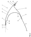
- FIG. 2 Another embodiment is shown in Figure 2, the here Vehicle body 11 is not shown.
- the fender arrangement 1 according to FIG. 2 corresponds essentially to that of the first embodiment, so that here for Similar elements are used and the same reference numerals No further explanation of these elements is necessary.
- the profile in FIG. 2 is again C-shaped Deformation element 6 provided with a slightly larger opening angle, so that the body-side leg 10 and the mounting portion 13 are slightly inclined.
- the body-side leg 10 can, however, in particular in its angular position, be easily adapted to the conditions on the vehicle body, as long as Large travel with a vertical load on the upper edge 3 of the fender 2 is guaranteed.
- the fender-side leg 9 forms a step 23 , to which a substantially extending in the vehicle transverse direction Edge section 24 connects.
- the edge section 24 is the contour of the outer skin of the Vehicle body adjusted in the area of the upper edge 3 of the fender 2 and lies on the inside against it.
- the fender is for connection to the edge section 24 2 folded around the edge section 24 and from the inside against the edge section 24 pressed to form a fold. This results in a particularly narrow one Top edge 3.
- the wall thicknesses of the fender 2, the deformation element 6 and the support part 16 are chosen according to the first embodiment, so that the second embodiment with a vertical load a high flexibility Mudguard 2 in the area between the upper edge 3 and the outer wall section 15, against which the support part 16 is leaned on the inside via a support adhesive 21, results.
- the deformation section 6 in one piece with the fender 2. However, these then have the same Wall thickness. By extending the wall section 12 of the Deformation section 6 up to close to the outer wall of the fender 2 results however, due to the long lever arm in relation to the upper edge 3 a high degree of compliance with a vertical load.
Landscapes
- Engineering & Computer Science (AREA)
- Chemical & Material Sciences (AREA)
- Combustion & Propulsion (AREA)
- Transportation (AREA)
- Mechanical Engineering (AREA)
- Body Structure For Vehicles (AREA)
Claims (11)
- Agencement de garde-boue pour un véhicule automobile, comprenant un garde-boue (2) et un élément de déformation (6) de section transversale avec un profil en forme de C en vue du support orienté essentiellement verticalement d'une arête supérieur (3) du garde-boue (2) contre une carrosserie du véhicule (11), une branche (9) du profil en C étant connectée dans la région de l'arête supérieure (3) au garde-boue (2) et l'autre branche (10) étant connectée à la carrosserie du véhicule (11), caractérisé en ce qu'une partie de support (16) est disposée entre la branche (10) de l'élément de déformation (6) du côté de la carrosserie et une portion de paroi extérieure (15) du garde-boue (2) espacée de l'arête supérieure (3), laquelle partie de support supporte la branche (10) du côté de la carrosserie et la portion de paroi extérieure (15) l'une contre l'autre.
- Agencement de garde-boue selon la revendication 1, caractérisé en ce que la partie de support (16) est disposée essentiellement transversalement à la direction de support de l'élément de déformation (6) et s'étend depuis la branche (10) du côté de la carrosserie vers l'extérieur vers la portion de paroi extérieure (15).
- Agencement de garde-boue selon la revendication 1 ou 2, caractérisé en ce que la partie de support (16) tombe dans la direction normale sur la portion de paroi extérieure (15) du garde-boue (2).
- Agencement de garde-boue selon l'une quelconque des revendications 1 à 3, caractérisé en ce que la partie de support (16) est recourbée avec son extrémité du côté de la paroi extérieure parallèlement à la portion de paroi extérieure (15).
- Agencement de garde-boue selon l'une quelconque des revendications 1 à 4, caractérisé en ce que la partie de support (16) est collée avec son extrémité du côté de la paroi extérieure au côté intérieur de la portion de paroi extérieure (15).
- Agencement de garde-boue selon l'une quelconque des revendications 1 à 5, caractérisé en ce que le profil de l'élément de déformation (6) sur la branche (9) du côté du garde-boue se termine essentiellement dans la direction transversale du véhicule.
- Agencement de garde-boue selon l'une quelconque des revendications 1 à 6, caractérisé en ce que le garde-boue (2) est soudé avec une portion de bord de la branche (9) du côté du garde-boue ou est emboíté avec la portion de bord (24).
- Agencement de garde-boue selon l'une quelconque des revendications 1 à 7, caractérisé en ce que la branche du côté de la carrosserie (10) est disposée de manière s'étendant essentiellement dans la direction transversale du véhicule et repose sur une portion de cadre de la carrosserie du véhicule (11).
- Agencement de garde-boue selon l'une quelconque des revendications 1 à 8, caractérisé en ce que la branche du côté de la carrosserie (10) est fixée de manière détachable sur la carrosserie du véhicule (11).
- Agencement de garde-boue selon l'une quelconque des revendications 1 à 9, caractérisé en ce que l'épaisseur de tôle de l'élément de déformation (6) est inférieure à l'épaisseur de tôle du garde-boue (2).
- Agencement de garde-boue selon l'une quelconque des revendications 1 à 10, caractérisé en ce que la partie de support (16) présente une épaisseur de tôle plus importante que l'élément de déformation (6).
Applications Claiming Priority (2)
| Application Number | Priority Date | Filing Date | Title |
|---|---|---|---|
| DE10009364 | 2000-02-29 | ||
| DE10009364A DE10009364A1 (de) | 2000-02-29 | 2000-02-29 | Kotflügelanordnung für ein Kraftfahrzeug |
Publications (3)
| Publication Number | Publication Date |
|---|---|
| EP1129928A2 EP1129928A2 (fr) | 2001-09-05 |
| EP1129928A3 EP1129928A3 (fr) | 2001-11-14 |
| EP1129928B1 true EP1129928B1 (fr) | 2003-05-07 |
Family
ID=7632714
Family Applications (1)
| Application Number | Title | Priority Date | Filing Date |
|---|---|---|---|
| EP01102764A Expired - Lifetime EP1129928B1 (fr) | 2000-02-29 | 2001-02-08 | Garde-boue pour un véhicule automobile |
Country Status (4)
| Country | Link |
|---|---|
| EP (1) | EP1129928B1 (fr) |
| AT (1) | ATE239637T1 (fr) |
| DE (2) | DE10009364A1 (fr) |
| ES (1) | ES2195959T3 (fr) |
Cited By (5)
| Publication number | Priority date | Publication date | Assignee | Title |
|---|---|---|---|---|
| DE102004011333A1 (de) * | 2004-03-09 | 2005-09-22 | Adam Opel Ag | Vorderbau für ein Kraftfahrzeug |
| DE102004011334A1 (de) * | 2004-03-09 | 2005-11-17 | Adam Opel Ag | Vorderbau für ein Kraftfahrzeug |
| DE102008010138A1 (de) | 2008-02-20 | 2009-08-27 | Dr. Ing. H.C. F. Porsche Aktiengesellschaft | Kotflügelanordnung |
| DE102010060800A1 (de) | 2010-11-25 | 2012-05-31 | Dr. Ing. H.C. F. Porsche Aktiengesellschaft | Kotflügelanordnung |
| CN115320723A (zh) * | 2022-08-29 | 2022-11-11 | 重庆长安汽车股份有限公司 | 一种可用于行人保护的汽车前部结构及车辆 |
Families Citing this family (13)
| Publication number | Priority date | Publication date | Assignee | Title |
|---|---|---|---|---|
| DE10206768B4 (de) * | 2002-02-19 | 2005-11-17 | Daimlerchrysler Ag | Kotflügelanordnung für ein Kraftfahrzeug |
| DE10242258A1 (de) * | 2002-09-12 | 2004-04-01 | Audi Ag | Kotflügelanordnung für ein Kraftfahrzeug |
| DE10244455A1 (de) | 2002-09-24 | 2004-05-13 | Volkswagen Ag | Kotflügelaufbau an Kraftfahrzeugen |
| DE10355735B4 (de) * | 2003-11-28 | 2007-11-29 | Benteler Automobiltechnik Gmbh | Kotflügelanordnung für ein Kraftfahrzeug |
| DE102004035422A1 (de) * | 2004-07-21 | 2006-03-16 | Adam Opel Ag | Vorderbau einer Karosserie für ein Kraftfahrzeug |
| DE102008028057A1 (de) | 2008-06-12 | 2009-12-17 | Volkswagen Ag | Anordnung zur crashoptimierten Lagerung einer Frontklappe eines Fahrzeugs |
| DE102009005055A1 (de) * | 2009-01-19 | 2010-07-22 | Bayerische Motoren Werke Aktiengesellschaft | Kraftfahrzeug mit einem Dach |
| DE102009020281B4 (de) * | 2009-05-07 | 2025-04-17 | Dr. Ing. H.C. F. Porsche Aktiengesellschaft | Vorbau eines Kraftfahrzeuges |
| US9783152B2 (en) | 2011-10-11 | 2017-10-10 | GM Global Technology Operations LLC | Vehicle impact reduction structure |
| US8485588B1 (en) * | 2012-05-11 | 2013-07-16 | GM Global Technology Operations LLC | Localized impact energy absorbers |
| DE102013012300A1 (de) | 2013-07-24 | 2014-03-27 | Daimler Ag | Kotflügel für einen Kraftwagen |
| JP7040341B2 (ja) | 2018-07-26 | 2022-03-23 | トヨタ自動車株式会社 | 車両用フェンダ構造 |
| DE102023122674B3 (de) * | 2023-08-24 | 2024-12-24 | Dr. Ing. H.C. F. Porsche Aktiengesellschaft | Vorderwagenstruktur eines Kraftfahrzeugs und Kraftfahrzeug |
Family Cites Families (8)
| Publication number | Priority date | Publication date | Assignee | Title |
|---|---|---|---|---|
| DE2922893A1 (de) | 1979-06-06 | 1980-12-11 | Porsche Ag | Endeinheit, vorzugsweise bugpartie eines kraftfahrzeuges |
| DE3047969A1 (de) | 1979-08-23 | 1982-07-22 | Daimler-Benz Ag, 7000 Stuttgart | Kraftfahrzeug, insbesondere personenkraftwagen |
| DE2934060A1 (de) | 1979-08-23 | 1981-03-26 | Daimler-Benz Aktiengesellschaft, 70567 Stuttgart | Kraftfahrzeug, insbesondere personenkraftwagen, mit nachgiebigen karosseriefrontteilen |
| JP2974040B2 (ja) * | 1993-05-28 | 1999-11-08 | 三菱自動車工業株式会社 | 車両のフェンダ装置 |
| DE4401023C1 (de) | 1994-01-15 | 1995-03-16 | Daimler Benz Ag | Kraftfahrzeugvorbau |
| JP3444773B2 (ja) | 1997-12-19 | 2003-09-08 | トヨタ自動車株式会社 | 自動車のフェンダー構造 |
| FR2773349B1 (fr) * | 1998-01-07 | 2000-03-03 | Hutchinson | Piece de carrosserie destinee a un vehicule automobile et son procede de fabrication |
| JPH11321717A (ja) * | 1998-05-19 | 1999-11-24 | Honda Motor Co Ltd | フェンダ構造 |
-
2000
- 2000-02-29 DE DE10009364A patent/DE10009364A1/de not_active Withdrawn
-
2001
- 2001-02-08 EP EP01102764A patent/EP1129928B1/fr not_active Expired - Lifetime
- 2001-02-08 ES ES01102764T patent/ES2195959T3/es not_active Expired - Lifetime
- 2001-02-08 DE DE50100219T patent/DE50100219D1/de not_active Expired - Lifetime
- 2001-02-08 AT AT01102764T patent/ATE239637T1/de not_active IP Right Cessation
Cited By (8)
| Publication number | Priority date | Publication date | Assignee | Title |
|---|---|---|---|---|
| DE102004011333A1 (de) * | 2004-03-09 | 2005-09-22 | Adam Opel Ag | Vorderbau für ein Kraftfahrzeug |
| DE102004011334A1 (de) * | 2004-03-09 | 2005-11-17 | Adam Opel Ag | Vorderbau für ein Kraftfahrzeug |
| DE102004011334B4 (de) * | 2004-03-09 | 2006-03-09 | Adam Opel Ag | Vorderbau für ein Kraftfahrzeug |
| DE102008010138A1 (de) | 2008-02-20 | 2009-08-27 | Dr. Ing. H.C. F. Porsche Aktiengesellschaft | Kotflügelanordnung |
| US7775585B2 (en) | 2008-02-20 | 2010-08-17 | Dr. Ing. H.C. F. Porsche Aktiengesellschaft | Fender configuration |
| DE102010060800A1 (de) | 2010-11-25 | 2012-05-31 | Dr. Ing. H.C. F. Porsche Aktiengesellschaft | Kotflügelanordnung |
| CN115320723A (zh) * | 2022-08-29 | 2022-11-11 | 重庆长安汽车股份有限公司 | 一种可用于行人保护的汽车前部结构及车辆 |
| CN115320723B (zh) * | 2022-08-29 | 2023-08-25 | 重庆长安汽车股份有限公司 | 一种可用于行人保护的汽车前部结构及车辆 |
Also Published As
| Publication number | Publication date |
|---|---|
| EP1129928A3 (fr) | 2001-11-14 |
| DE10009364A1 (de) | 2001-08-30 |
| EP1129928A2 (fr) | 2001-09-05 |
| DE50100219D1 (de) | 2003-06-12 |
| ES2195959T3 (es) | 2003-12-16 |
| ATE239637T1 (de) | 2003-05-15 |
Similar Documents
| Publication | Publication Date | Title |
|---|---|---|
| EP1129928B1 (fr) | Garde-boue pour un véhicule automobile | |
| EP1132263B1 (fr) | Dispositif de garde-boue pour un véhicule automobile | |
| EP1027223B1 (fr) | Renforcement interieur integre de portiere | |
| DE19534957C2 (de) | Insassenschutzanordnung an oberen Abschnitten einer Kraftfahrzeug-Karosserie | |
| DE102007042292B4 (de) | Plastisch verformbare Doppelzellenverbindung für die Front von Automobilen | |
| DE60220110T2 (de) | Verfahren zum Herstellen einer Fahrzeugrahmenanordnung mit kastenförmigem Knautschteil | |
| DE60211255T2 (de) | Fahrzeugvorderwagenaufbau | |
| EP2057041B1 (fr) | Dispositif d'absorption d'energie, en particulier pour une charge non axiale | |
| DE19948363A1 (de) | Mittelsäulenstruktur | |
| EP4035951B1 (fr) | Dispositif pare-chocs pour un véhicule automobile | |
| EP3022086B1 (fr) | Structure de dossier de siège de véhicule et siège de véhicule | |
| DE602004013204T2 (de) | Anordnung für fahrzeugkabinen | |
| EP0252232B1 (fr) | Dispositif d'arrêt pour une colonne de direction de véhicule automobile | |
| DE102016223216A1 (de) | Karosserie-Bodenstruktur für ein Fahrzeug | |
| EP0814011A1 (fr) | Système de direction | |
| EP4035950B1 (fr) | Agencement de pare-chocs à profilé creux d'extrémité | |
| DE19812679B4 (de) | Versteifungsanordnung für eine Unterbaugruppe eines Kraftfahrzeugs | |
| DE19959606A1 (de) | Fahrzeugseitenblech mit aufprallweicher Außenkante | |
| DE19901070C1 (de) | Befestigungsanordnung eines Türschwellers am Bodenblech eines Kraftwagens | |
| DE10016916B4 (de) | Vorrichtung zum Schutz eines Passanten bei einem Zusammenprall mit einem Kraftfahrzeug | |
| EP1084935A2 (fr) | Chassis auxiliaire d'un carrosserie de véhicule automobile pour absorber l'énergie de collision | |
| DE602004009938T2 (de) | Verformbarer längsträger für ein kraftfahrzeug | |
| DE10232799B4 (de) | Vorbaustruktur an Kraftfahrzeugen | |
| DE10003624B4 (de) | Sicherheitseinrichtung an der Fronthaube eines Fahrzeugs, insbesondere eines Kraftfahrzeugs | |
| EP0825094B1 (fr) | Carrosserie avant pour un véhicule à moteur |
Legal Events
| Date | Code | Title | Description |
|---|---|---|---|
| PUAI | Public reference made under article 153(3) epc to a published international application that has entered the european phase |
Free format text: ORIGINAL CODE: 0009012 |
|
| AK | Designated contracting states |
Kind code of ref document: A2 Designated state(s): AT BE CH CY DE DK ES FI FR GB GR IE IT LI LU MC NL PT SE TR |
|
| AX | Request for extension of the european patent |
Free format text: AL;LT;LV;MK;RO;SI |
|
| PUAL | Search report despatched |
Free format text: ORIGINAL CODE: 0009013 |
|
| AK | Designated contracting states |
Kind code of ref document: A3 Designated state(s): AT BE CH CY DE DK ES FI FR GB GR IE IT LI LU MC NL PT SE TR |
|
| AX | Request for extension of the european patent |
Free format text: AL;LT;LV;MK;RO;SI |
|
| RIC1 | Information provided on ipc code assigned before grant |
Free format text: 7B 62D 25/16 A, 7B 60R 21/34 B |
|
| 17P | Request for examination filed |
Effective date: 20020514 |
|
| AKX | Designation fees paid |
Free format text: AT BE CH CY DE DK ES FI FR GB GR IE IT LI LU MC NL PT SE TR |
|
| GRAH | Despatch of communication of intention to grant a patent |
Free format text: ORIGINAL CODE: EPIDOS IGRA |
|
| GRAH | Despatch of communication of intention to grant a patent |
Free format text: ORIGINAL CODE: EPIDOS IGRA |
|
| GRAA | (expected) grant |
Free format text: ORIGINAL CODE: 0009210 |
|
| AK | Designated contracting states |
Designated state(s): AT BE CH CY DE DK ES FI FR GB GR IE IT LI LU MC NL PT SE TR |
|
| PG25 | Lapsed in a contracting state [announced via postgrant information from national office to epo] |
Ref country code: FI Free format text: LAPSE BECAUSE OF FAILURE TO SUBMIT A TRANSLATION OF THE DESCRIPTION OR TO PAY THE FEE WITHIN THE PRESCRIBED TIME-LIMIT Effective date: 20030507 Ref country code: TR Free format text: LAPSE BECAUSE OF FAILURE TO SUBMIT A TRANSLATION OF THE DESCRIPTION OR TO PAY THE FEE WITHIN THE PRESCRIBED TIME-LIMIT Effective date: 20030507 Ref country code: IE Free format text: LAPSE BECAUSE OF NON-PAYMENT OF DUE FEES Effective date: 20030507 Ref country code: CY Free format text: LAPSE BECAUSE OF FAILURE TO SUBMIT A TRANSLATION OF THE DESCRIPTION OR TO PAY THE FEE WITHIN THE PRESCRIBED TIME-LIMIT Effective date: 20030507 Ref country code: NL Free format text: LAPSE BECAUSE OF FAILURE TO SUBMIT A TRANSLATION OF THE DESCRIPTION OR TO PAY THE FEE WITHIN THE PRESCRIBED TIME-LIMIT Effective date: 20030507 |
|
| REG | Reference to a national code |
Ref country code: GB Ref legal event code: FG4D Free format text: NOT ENGLISH |
|
| REG | Reference to a national code |
Ref country code: CH Ref legal event code: EP |
|
| REG | Reference to a national code |
Ref country code: IE Ref legal event code: FG4D Free format text: GERMAN |
|
| REF | Corresponds to: |
Ref document number: 50100219 Country of ref document: DE Date of ref document: 20030612 Kind code of ref document: P |
|
| PG25 | Lapsed in a contracting state [announced via postgrant information from national office to epo] |
Ref country code: PT Free format text: LAPSE BECAUSE OF FAILURE TO SUBMIT A TRANSLATION OF THE DESCRIPTION OR TO PAY THE FEE WITHIN THE PRESCRIBED TIME-LIMIT Effective date: 20030807 Ref country code: SE Free format text: LAPSE BECAUSE OF FAILURE TO SUBMIT A TRANSLATION OF THE DESCRIPTION OR TO PAY THE FEE WITHIN THE PRESCRIBED TIME-LIMIT Effective date: 20030807 Ref country code: GR Free format text: LAPSE BECAUSE OF FAILURE TO SUBMIT A TRANSLATION OF THE DESCRIPTION OR TO PAY THE FEE WITHIN THE PRESCRIBED TIME-LIMIT Effective date: 20030807 Ref country code: DK Free format text: LAPSE BECAUSE OF FAILURE TO SUBMIT A TRANSLATION OF THE DESCRIPTION OR TO PAY THE FEE WITHIN THE PRESCRIBED TIME-LIMIT Effective date: 20030807 |
|
| GBT | Gb: translation of ep patent filed (gb section 77(6)(a)/1977) | ||
| NLV1 | Nl: lapsed or annulled due to failure to fulfill the requirements of art. 29p and 29m of the patents act | ||
| REG | Reference to a national code |
Ref country code: ES Ref legal event code: FG2A Ref document number: 2195959 Country of ref document: ES Kind code of ref document: T3 |
|
| REG | Reference to a national code |
Ref country code: IE Ref legal event code: FD4D Ref document number: 1129928E Country of ref document: IE |
|
| ET | Fr: translation filed | ||
| PG25 | Lapsed in a contracting state [announced via postgrant information from national office to epo] |
Ref country code: LU Free format text: LAPSE BECAUSE OF NON-PAYMENT OF DUE FEES Effective date: 20040208 Ref country code: AT Free format text: LAPSE BECAUSE OF NON-PAYMENT OF DUE FEES Effective date: 20040208 |
|
| PLBI | Opposition filed |
Free format text: ORIGINAL CODE: 0009260 |
|
| PLBQ | Unpublished change to opponent data |
Free format text: ORIGINAL CODE: EPIDOS OPPO |
|
| PG25 | Lapsed in a contracting state [announced via postgrant information from national office to epo] |
Ref country code: BE Free format text: LAPSE BECAUSE OF NON-PAYMENT OF DUE FEES Effective date: 20040228 Ref country code: MC Free format text: LAPSE BECAUSE OF NON-PAYMENT OF DUE FEES Effective date: 20040228 |
|
| 26 | Opposition filed |
Opponent name: DAIMLERCHRYSLER AG Effective date: 20040209 |
|
| PLAX | Notice of opposition and request to file observation + time limit sent |
Free format text: ORIGINAL CODE: EPIDOSNOBS2 |
|
| BERE | Be: lapsed |
Owner name: *VOLKSWAGEN A.G. Effective date: 20040228 |
|
| PLBB | Reply of patent proprietor to notice(s) of opposition received |
Free format text: ORIGINAL CODE: EPIDOSNOBS3 |
|
| PG25 | Lapsed in a contracting state [announced via postgrant information from national office to epo] |
Ref country code: CH Free format text: LAPSE BECAUSE OF NON-PAYMENT OF DUE FEES Effective date: 20050228 Ref country code: LI Free format text: LAPSE BECAUSE OF NON-PAYMENT OF DUE FEES Effective date: 20050228 |
|
| REG | Reference to a national code |
Ref country code: CH Ref legal event code: PL |
|
| PLBD | Termination of opposition procedure: decision despatched |
Free format text: ORIGINAL CODE: EPIDOSNOPC1 |
|
| PLBP | Opposition withdrawn |
Free format text: ORIGINAL CODE: 0009264 |
|
| PLBM | Termination of opposition procedure: date of legal effect published |
Free format text: ORIGINAL CODE: 0009276 |
|
| STAA | Information on the status of an ep patent application or granted ep patent |
Free format text: STATUS: OPPOSITION PROCEDURE CLOSED |
|
| 27C | Opposition proceedings terminated |
Effective date: 20060317 |
|
| REG | Reference to a national code |
Ref country code: FR Ref legal event code: PLFP Year of fee payment: 16 |
|
| REG | Reference to a national code |
Ref country code: FR Ref legal event code: PLFP Year of fee payment: 17 |
|
| PGFP | Annual fee paid to national office [announced via postgrant information from national office to epo] |
Ref country code: IT Payment date: 20170224 Year of fee payment: 17 |
|
| REG | Reference to a national code |
Ref country code: FR Ref legal event code: PLFP Year of fee payment: 18 |
|
| PG25 | Lapsed in a contracting state [announced via postgrant information from national office to epo] |
Ref country code: IT Free format text: LAPSE BECAUSE OF NON-PAYMENT OF DUE FEES Effective date: 20180208 |
|
| PGFP | Annual fee paid to national office [announced via postgrant information from national office to epo] |
Ref country code: DE Payment date: 20200229 Year of fee payment: 20 Ref country code: GB Payment date: 20200226 Year of fee payment: 20 Ref country code: ES Payment date: 20200323 Year of fee payment: 20 |
|
| PGFP | Annual fee paid to national office [announced via postgrant information from national office to epo] |
Ref country code: FR Payment date: 20200225 Year of fee payment: 20 |
|
| REG | Reference to a national code |
Ref country code: DE Ref legal event code: R071 Ref document number: 50100219 Country of ref document: DE |
|
| REG | Reference to a national code |
Ref country code: GB Ref legal event code: PE20 Expiry date: 20210207 |
|
| PG25 | Lapsed in a contracting state [announced via postgrant information from national office to epo] |
Ref country code: GB Free format text: LAPSE BECAUSE OF EXPIRATION OF PROTECTION Effective date: 20210207 |
|
| REG | Reference to a national code |
Ref country code: ES Ref legal event code: FD2A Effective date: 20220128 |
|
| PG25 | Lapsed in a contracting state [announced via postgrant information from national office to epo] |
Ref country code: ES Free format text: LAPSE BECAUSE OF EXPIRATION OF PROTECTION Effective date: 20210209 |
|
| P01 | Opt-out of the competence of the unified patent court (upc) registered |
Effective date: 20230523 |