EP1132263B1 - Dispositif de garde-boue pour un véhicule automobile - Google Patents
Dispositif de garde-boue pour un véhicule automobile Download PDFInfo
- Publication number
- EP1132263B1 EP1132263B1 EP01102763A EP01102763A EP1132263B1 EP 1132263 B1 EP1132263 B1 EP 1132263B1 EP 01102763 A EP01102763 A EP 01102763A EP 01102763 A EP01102763 A EP 01102763A EP 1132263 B1 EP1132263 B1 EP 1132263B1
- Authority
- EP
- European Patent Office
- Prior art keywords
- wheel guard
- wall
- fender
- upper edge
- reinforcing part
- Prior art date
- Legal status (The legal status is an assumption and is not a legal conclusion. Google has not performed a legal analysis and makes no representation as to the accuracy of the status listed.)
- Expired - Lifetime
Links
Images

Classifications
-
- B—PERFORMING OPERATIONS; TRANSPORTING
- B62—LAND VEHICLES FOR TRAVELLING OTHERWISE THAN ON RAILS
- B62D—MOTOR VEHICLES; TRAILERS
- B62D25/00—Superstructure or monocoque structure sub-units; Parts or details thereof not otherwise provided for
- B62D25/08—Front or rear portions
- B62D25/16—Mud-guards or wings; Wheel cover panels
-
- B—PERFORMING OPERATIONS; TRANSPORTING
- B60—VEHICLES IN GENERAL
- B60R—VEHICLES, VEHICLE FITTINGS, OR VEHICLE PARTS, NOT OTHERWISE PROVIDED FOR
- B60R21/00—Arrangements or fittings on vehicles for protecting or preventing injuries to occupants or pedestrians in case of accidents or other traffic risks
- B60R21/34—Protecting non-occupants of a vehicle, e.g. pedestrians
-
- B—PERFORMING OPERATIONS; TRANSPORTING
- B62—LAND VEHICLES FOR TRAVELLING OTHERWISE THAN ON RAILS
- B62D—MOTOR VEHICLES; TRAILERS
- B62D25/00—Superstructure or monocoque structure sub-units; Parts or details thereof not otherwise provided for
- B62D25/08—Front or rear portions
- B62D25/16—Mud-guards or wings; Wheel cover panels
- B62D25/163—Mounting devices
-
- B—PERFORMING OPERATIONS; TRANSPORTING
- B60—VEHICLES IN GENERAL
- B60R—VEHICLES, VEHICLE FITTINGS, OR VEHICLE PARTS, NOT OTHERWISE PROVIDED FOR
- B60R21/00—Arrangements or fittings on vehicles for protecting or preventing injuries to occupants or pedestrians in case of accidents or other traffic risks
- B60R21/34—Protecting non-occupants of a vehicle, e.g. pedestrians
- B60R2021/343—Protecting non-occupants of a vehicle, e.g. pedestrians using deformable body panel, bodywork or components
Definitions
- the invention relates to a fender arrangement for a motor vehicle and its accident-proof design with regard to a collision of the motor vehicle with an unprotected person, for example a pedestrian, around the Reduce risk of injury to the person.
- JP 11180350 a fender arrangement is known in which the Support against a vehicle side member via a deformation element with a box-like profile is made.
- the deformation element projects above the Side member outwards, so that in the event of a person impact on the upper edge of the Fender the body side leg of the profile can buckle.
- the Mudguards have sufficient structural rigidity to maintain the integrity of the Maintain vehicle outer skin during operation.
- the fenders also serve to absorb crash energy from one Collision with a serious obstacle, so that its weakening is a Deterioration in occupant safety would mean.
- the invention is based on the object Impact of a motor vehicle the risk of injury or the severity of To further reduce injuries to the accident victim.
- a fender arrangement for a motor vehicle comprising a fender with an upper edge, a reinforcing member that runs along the Upper edge is provided on the inside of the fender, the fender along its upper edge forms a hollow profile together with the reinforcing part and that Reinforcing member profile one to the opposite outer wall of the fender roughly parallel and spaced from this wall section, which over a first leg on the top edge and a second leg on one of the Upper edge spaced outer wall portion of the fender is supported, and at least one connecting part, via which the spaced from the upper edge Outer wall section can be supported against a vehicle body.
- the front hood as a single-walled, freely projecting sheet metal section. at a vertical load would be particularly soft. Such a sheet metal section would tend to flutter when vibrating.
- the area of the upper edge is formed by a hollow profile, the one hand allows greater flexibility compared to conventional arrangements, but in With regard to the occurrence of possible vibrations of the fender assembly this gives necessary rigidity. From the increased flexibility of this area result from a human impact compared to conventional ones Fender arrangements lower delay values, increasing the risk of injury is reduced.
- connection of the fender via the at least one connecting part is guaranteed moreover, the extensive use of the deformation potential of the fender Incorporation of crash energy with a view to occupant safety, at a not only connecting the fender over a very flexible wall section more would be given, since the wall section would be destroyed prematurely. That in essentially hollow profile extending in the vehicle longitudinal direction has an advantageous effect the energy absorption capacity of the fender.
- the reinforcing part is in profile trough-shaped. It can thus be produced particularly easily as a sheet metal part become.
- the arrangement of the reinforcing part is preferably such that that of the Outer wall of the fender spaced wall section between the legs in Vehicle transverse direction runs obliquely downwards from the inside to the outside.
- the fender is attached to at least one of the legs bent at its end to a mounting flange, the respective Fastening flange essentially parallel to the outer wall contour of the fender is trained. Furthermore, this results in the possibility of a wide area of externally invisible connection of the fender to the reinforcement part.
- top edge spaced second leg in the normal direction on the inside of the Outer wall section of the fender meets. This results in an effective one Support in the event of lateral forces acting on the fender, for example when a person is leaning against the fender. Permanent deformation of the fender are avoided in this case.
- the fender can be welded to the first leg at the upper edge become.
- the parting line must then be installed in the vehicle if possible, so that it is not visible from the outside.
- the invention is the fender on the upper edge around an edge portion of the first Leg of the reinforcing part folded. This keeps the shape of each other easy to combine.
- a relatively thin-walled structure that is not vertical extending, and because of their reinforcing effect undesirable in this area Wall sections gets along.
- the fender-side connection of the connecting part is preferably carried out via the second Leg, so that the outer wall of the fender from its actual support remains unaffected against the vehicle body. The danger of being stamped out End of the connecting part in the fender is avoided.
- Connecting parts can also use a plurality of separate connecting parts become.
- the profile base of the reinforcing part is preferably in the region of the connection of the Connection part spaced further from the outer wall than the profile floor between adjacent connecting parts is spaced from the outer wall. In addition to one Larger support surface for the reinforcement part still results from this locally increased rigidity in those relevant for the introduction of force into the fender Wall areas.
- the reinforcement part essentially takes over the function, for a sufficient Ensure stability of the area around the top edge of the fender. On the other hand, should a high degree of flexibility in this area remains guaranteed. This is it particularly advantageous if the reinforcing part has a smaller wall thickness than the fender.
- the or the connecting parts have a greater wall thickness than the reinforcing part.
- the fender, the reinforcing part and the connecting part are as separate elements are formed, which then remain simple in shape.
- the reinforcing part and the fender also be integrally formed with each other.
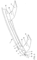
- the embodiment in Figures 1 to 3 shows a fender assembly 1 for a Passenger vehicle.
- the fender assembly 1 first includes a fender 2, the is formed as a sheet metal part.
- An upper edge 3 is formed on the fender 2, which along the side edge 4 of a front hood 5 of the motor vehicle essentially runs in the longitudinal direction of the vehicle.
- the top edge 3 of the fender 2 and the side edge 4 of the front hood 5 form a parting line, which in conventional vehicle bodies in the case of personal accidents due to the greater structural rigidity there represents increased risk of injury, since in particular the upper edge 3 over a relatively rigid wall section against a frame section of a Vehicle body is supported.
- the fender assembly 1 comprises a reinforcing part 6, which along the Upper edge 3 is arranged on the inside of the fender 2.
- the reinforcing member 6 has trough-like cross-sectional profile that one to the opposite outer wall of the fender 2 roughly parallel and spaced from this wall section as Profile floor 7 as well as two legs 8 and 9 adjoining them laterally formed.
- the wall section or profile floor spaced from the outer wall of the fender 2 7 runs from inside to outside and at an angle when viewed in the transverse direction of the vehicle downward.
- a first leg 8 extends from the profile floor 7 to the inner wall of the Fender 2.
- the fender end of the leg 8 is substantially in Vehicle transverse direction bent according to the outer contour of the fender 2.
- This bent wall section 10 extends to the upper edge 3, where it from an edge 11 of the fender 2 is enclosed.
- the edge 11 is around the Wall section 10 folded around and folded with this.
- the second leg 9 runs essentially in the normal direction on the outer wall of the fender 2, that is to say more precisely to a distance from the upper edge 3 Outer wall section 12 of the fender 2 to the inside against this support.
- the second leg 9 is after it Profile outside bent to a substantially parallel to the To form outer wall portion 12 extending flange portion 13.
- the reinforcing member 6 is fixed to the inner wall of the Outer wall section 12 connected. Since the outer wall portion 12 is part of the Represents the outer skin of the vehicle, connection techniques are required here, which do not affect the outside of the outer wall portion 12. In which The embodiment shown here is therefore the end of the reinforcing part 6 at the Glued inner wall of the outer wall portion 12. This is between the Flange section 13 and the inside of the outer wall section 12 a support adhesive 14 provided.
- This support adhesive 14 has one in the undeformed state circular cross section and is on one side in an arcuate groove 15 on the Flange section 13 added.
- the groove 15 extends essentially in Vehicle longitudinal direction.
- the support adhesive 14 consists, for example, of a Epoxy resin.
- the support of the inner wall of the fender 2 on the reinforcing part 6 is preferably carried out only via the support adhesive 14, so that the Do not touch flange section 13 and the inner wall directly.
- the hollow profile is connected to a section of a section, not shown here Vehicle frame via at least one connecting part 16.
- This connecting part can can be provided along the entire length of the hollow profile.
- Connecting parts 16 are two spaced apart Connecting parts 16 used, each as elongated in the vehicle transverse direction Metal strips are formed.
- Each connecting part 16 can be fastened with one end 17 to the vehicle frame.
- the end 17 can be attached to the vehicle frame by welding, soldering, riveting, Folding or gluing can be connected.
- a detachable connection is preferred,
- a screw connection is provided, which in the event of damage to the Mudguard 2 allows a quick and easy replacement of the same.
- the other end 18 of the connecting part 16 which is angled upward for this purpose, lies against a substantially flat outer wall of the second leg 9 and is with this firmly connected.
- the aforementioned connection techniques can be used be used.
- the other end 18 of the connecting part is preferred 16 welded to the second leg 9.
- the profile bottom 7 of the hollow profile in the area 19 of the connection points Connecting parts 16 bulged more from the inside of the fender 2. So that's the Profile floor 7 of the reinforcing part 6 in the area 19 of the connection of the connecting part 16 is spaced further from the outer wall of the fender 2 than between adjacent connecting parts 16, from which a for the suspension of the fender 2 local increase in stiffness results.
- the reinforcing part 6 and the one or more Connecting parts 16 formed as sheet metal parts.
- the reinforcing part 6 has a lower rigidity, in particular a smaller one Wall thickness on than the fender 2.
- the wall thickness of the reinforcing part 6 is in Range of 50 to 80% of the wall thickness of the fender 2.
- the connecting part 16 is on the other hand, thicker than the reinforcing part 6.
- the wall thickness of the Reinforcement part 16 may be smaller than the wall thickness of the fender 2.
- the very flexible design of the area of the upper edge 3 results in a lower impact than conventional fender arrangements Delay, which reduces the risk of injury. With a jerky Vertical impact on the upper area of the fender 2 makes the impact soft intercepted. Since a certain stiffening effect from the connecting parts 16 results, the connecting parts 16 are preferably arranged where with a lower impact probability is to be expected.
Landscapes
- Engineering & Computer Science (AREA)
- Mechanical Engineering (AREA)
- Chemical & Material Sciences (AREA)
- Combustion & Propulsion (AREA)
- Transportation (AREA)
- Body Structure For Vehicles (AREA)
Claims (11)
- Dispositif de garde-boue pour un véhicule automobile, comprenant un garde-boue (2) avec une arête supérieure (3), une pièce de renforcement (6), qui est prévue le long de l'arête supérieure (3) sur un côté intérieur du garde-boue (2), dans lequel le garde-boue (2) forme le long de son arête supérieure (3) un profil creux avec la pièce de renforcement (6) et dans lequel le profil de la pièce de renforcement (6) présente une partie de paroi (7) grossièrement parallèle à la paroi extérieure opposée du garde-boue (2) et distante de celle-ci, qui prend appui par une première aile (8) sur l'arête supérieure (3) et par une seconde aile (9) sur une partie de paroi extérieure (12) du garde-boue (2) distante de l'arête supérieure (3), et au moins une pièce de liaison (16), par laquelle la partie de paroi extérieure (12) distante de l'arête supérieure (3) peut être appuyée sur une structure du véhicule.
- Dispositif de garde-boue suivant la revendication 1, caractérisé en ce que la pièce de renforcement (6) présente un profil en forme de cuvette.
- Dispositif de garde-boue suivant la revendication 1 ou 2, caractérisé en ce que la partie de paroi (7) distante de la paroi extérieure du garde-boue (2) et située entre les ailes (8, 9) est orientée en oblique vers le bas de l'intérieur vers l'extérieur dans le sens transversal du véhicule.
- Dispositif de garde-boue suivant l'une quelconque des revendications 1 à 3, caractérisé en ce qu'au moins une des ailes (8, 9) est recourbée à son extrémité en une bride de fixation (10, 13), de telle manière que chaque bride de fixation soit orientée sensiblement parallèlement au contour de la paroi extérieure du garde-boue (2).
- Dispositif de garde-boue suivant l'une quelconque des revendications 1 à 4, caractérisé en ce que le garde-boue (2) est replié à l'arête supérieure (3) autour d'une partie de bord (10) de la première aile (8) de la pièce de renforcement (6).
- Dispositif de garde-boue suivant l'une quelconque des revendications 1 à 4, caractérisé en ce que la pièce de renforcement (6) est formée d'un seul tenant avec le garde-boue (2).
- Dispositif de garde-boue suivant l'une quelconque des revendications 1 à 6, caractérisé en ce que la seconde aile (9) distante de l'arête supérieure (3) arrive en direction normale sur le côté intérieur de la partie de paroi extérieure (12) du garde-boue (2).
- Dispositif de garde-boue suivant l'une quelconque des revendications 1 à 7, caractérisé en ce qu'il est prévu au moins une pièce de liaison (16), par laquelle la seconde aile (9) prend appui sur une structure du véhicule.
- Dispositif de garde-boue suivant l'une quelconque des revendications 1 à 8, caractérisé en ce que la partie de paroi (7) de la pièce de renforcement (6), distante de la paroi extérieure du garde-boue (2), est plus distante de la paroi extérieure dans la région de la jonction de la pièce de liaison (16) que la partie de paroi (7) n'est distante de la paroi extérieure entre des pièces de liaison (16) voisines.
- Dispositif de garde-boue suivant l'une quelconque des revendications 1 à 9, caractérisé en ce que la pièce de renforcement (6) présente une épaisseur de paroi plus faible que le garde-boue (2).
- Dispositif de garde-boue suivant l'une quelconque des revendications 1 à 10, caractérisé en ce que la pièce de liaison (16) présente une plus grande épaisseur de paroi que la pièce de renforcement (6).
Applications Claiming Priority (2)
| Application Number | Priority Date | Filing Date | Title |
|---|---|---|---|
| DE10009363 | 2000-02-29 | ||
| DE10009363A DE10009363A1 (de) | 2000-02-29 | 2000-02-29 | Kotflügelanordnung für ein Kraftfahrzeug |
Publications (3)
| Publication Number | Publication Date |
|---|---|
| EP1132263A1 EP1132263A1 (fr) | 2001-09-12 |
| EP1132263B1 true EP1132263B1 (fr) | 2003-05-07 |
| EP1132263B2 EP1132263B2 (fr) | 2006-04-26 |
Family
ID=7632713
Family Applications (1)
| Application Number | Title | Priority Date | Filing Date |
|---|---|---|---|
| EP01102763A Expired - Lifetime EP1132263B2 (fr) | 2000-02-29 | 2001-02-08 | Dispositif de garde-boue pour un véhicule automobile |
Country Status (3)
| Country | Link |
|---|---|
| EP (1) | EP1132263B2 (fr) |
| AT (1) | ATE239630T1 (fr) |
| DE (2) | DE10009363A1 (fr) |
Families Citing this family (39)
| Publication number | Priority date | Publication date | Assignee | Title |
|---|---|---|---|---|
| DE10206768B4 (de) | 2002-02-19 | 2005-11-17 | Daimlerchrysler Ag | Kotflügelanordnung für ein Kraftfahrzeug |
| DE10317178B3 (de) * | 2003-04-15 | 2004-10-21 | Benteler Automobiltechnik Gmbh | Kraftfahrzeug |
| DE102004011333A1 (de) * | 2004-03-09 | 2005-09-22 | Adam Opel Ag | Vorderbau für ein Kraftfahrzeug |
| DE102005027176A1 (de) * | 2005-06-13 | 2006-12-21 | GM Global Technology Operations, Inc., Detroit | Vorderbau für ein Kraftfahrzeug |
| DE102008010138A1 (de) | 2008-02-20 | 2009-08-27 | Dr. Ing. H.C. F. Porsche Aktiengesellschaft | Kotflügelanordnung |
| US9812684B2 (en) | 2010-11-09 | 2017-11-07 | GM Global Technology Operations LLC | Using elastic averaging for alignment of battery stack, fuel cell stack, or other vehicle assembly |
| US9061403B2 (en) | 2011-07-21 | 2015-06-23 | GM Global Technology Operations LLC | Elastic tube alignment system for precisely locating an emblem lens to an outer bezel |
| US9067379B2 (en) | 2012-04-28 | 2015-06-30 | GM Global Technologies Operations LLC | Stiffened multi-layer compartment door assembly utilizing elastic averaging |
| US9618026B2 (en) | 2012-08-06 | 2017-04-11 | GM Global Technology Operations LLC | Semi-circular alignment features of an elastic averaging alignment system |
| US9061715B2 (en) * | 2012-08-09 | 2015-06-23 | GM Global Technology Operations LLC | Elastic cantilever beam alignment system for precisely aligning components |
| US9463538B2 (en) | 2012-08-13 | 2016-10-11 | GM Global Technology Operations LLC | Alignment system and method thereof |
| US9556890B2 (en) | 2013-01-31 | 2017-01-31 | GM Global Technology Operations LLC | Elastic alignment assembly for aligning mated components and method of reducing positional variation |
| US9156506B2 (en) | 2013-03-27 | 2015-10-13 | GM Global Technology Operations LLC | Elastically averaged alignment system |
| US9278642B2 (en) | 2013-04-04 | 2016-03-08 | GM Global Technology Operations LLC | Elastically deformable flange locator arrangement and method of reducing positional variation |
| US9382935B2 (en) | 2013-04-04 | 2016-07-05 | GM Global Technology Operations LLC | Elastic tubular attachment assembly for mating components and method of mating components |
| US9388838B2 (en) | 2013-04-04 | 2016-07-12 | GM Global Technology Operations LLC | Elastic retaining assembly for matable components and method of assembling |
| US9297400B2 (en) | 2013-04-08 | 2016-03-29 | GM Global Technology Operations LLC | Elastic mating assembly and method of elastically assembling matable components |
| US9067625B2 (en) | 2013-04-09 | 2015-06-30 | GM Global Technology Operations LLC | Elastic retaining arrangement for jointed components and method of reducing a gap between jointed components |
| US9447840B2 (en) | 2013-06-11 | 2016-09-20 | GM Global Technology Operations LLC | Elastically deformable energy management assembly and method of managing energy absorption |
| US9243655B2 (en) | 2013-06-13 | 2016-01-26 | GM Global Technology Operations LLC | Elastic attachment assembly and method of reducing positional variation and increasing stiffness |
| US9488205B2 (en) | 2013-07-12 | 2016-11-08 | GM Global Technology Operations LLC | Alignment arrangement for mated components and method |
| US9303667B2 (en) | 2013-07-18 | 2016-04-05 | Gm Global Technology Operations, Llc | Lobular elastic tube alignment system for providing precise four-way alignment of components |
| US9863454B2 (en) | 2013-08-07 | 2018-01-09 | GM Global Technology Operations LLC | Alignment system for providing precise alignment and retention of components of a sealable compartment |
| US9463831B2 (en) | 2013-09-09 | 2016-10-11 | GM Global Technology Operations LLC | Elastic tube alignment and fastening system for providing precise alignment and fastening of components |
| US9457845B2 (en) | 2013-10-02 | 2016-10-04 | GM Global Technology Operations LLC | Lobular elastic tube alignment and retention system for providing precise alignment of components |
| US9511802B2 (en) | 2013-10-03 | 2016-12-06 | GM Global Technology Operations LLC | Elastically averaged alignment systems and methods |
| US9669774B2 (en) | 2013-10-11 | 2017-06-06 | GM Global Technology Operations LLC | Reconfigurable vehicle interior assembly |
| US9481317B2 (en) | 2013-11-15 | 2016-11-01 | GM Global Technology Operations LLC | Elastically deformable clip and method |
| US9428123B2 (en) | 2013-12-12 | 2016-08-30 | GM Global Technology Operations LLC | Alignment and retention system for a flexible assembly |
| US9447806B2 (en) | 2013-12-12 | 2016-09-20 | GM Global Technology Operations LLC | Self-retaining alignment system for providing precise alignment and retention of components |
| US9216704B2 (en) | 2013-12-17 | 2015-12-22 | GM Global Technology Operations LLC | Elastically averaged strap systems and methods |
| US9446722B2 (en) | 2013-12-19 | 2016-09-20 | GM Global Technology Operations LLC | Elastic averaging alignment member |
| US9599279B2 (en) | 2013-12-19 | 2017-03-21 | GM Global Technology Operations LLC | Elastically deformable module installation assembly |
| US9238488B2 (en) | 2013-12-20 | 2016-01-19 | GM Global Technology Operations LLC | Elastically averaged alignment systems and methods |
| US9541113B2 (en) | 2014-01-09 | 2017-01-10 | GM Global Technology Operations LLC | Elastically averaged alignment systems and methods |
| US9463829B2 (en) | 2014-02-20 | 2016-10-11 | GM Global Technology Operations LLC | Elastically averaged alignment systems and methods |
| US9428046B2 (en) | 2014-04-02 | 2016-08-30 | GM Global Technology Operations LLC | Alignment and retention system for laterally slideably engageable mating components |
| US9429176B2 (en) | 2014-06-30 | 2016-08-30 | GM Global Technology Operations LLC | Elastically averaged alignment systems and methods |
| US9758110B2 (en) | 2015-01-12 | 2017-09-12 | GM Global Technology Operations LLC | Coupling system |
Citations (1)
| Publication number | Priority date | Publication date | Assignee | Title |
|---|---|---|---|---|
| FR2773349A1 (fr) * | 1998-01-07 | 1999-07-09 | Hutchinson | Piece de carrosserie destinee a un vehicule automobile et son procede de fabrication |
Family Cites Families (5)
| Publication number | Priority date | Publication date | Assignee | Title |
|---|---|---|---|---|
| JP3052727B2 (ja) * | 1994-04-18 | 2000-06-19 | 日産自動車株式会社 | 車体前部の上部構造 |
| US5706908A (en) * | 1994-04-18 | 1998-01-13 | Nissan Motor Co., Ltd. | Front upper structure of automotive vehicle |
| JP3444773B2 (ja) * | 1997-12-19 | 2003-09-08 | トヨタ自動車株式会社 | 自動車のフェンダー構造 |
| JPH11321717A (ja) * | 1998-05-19 | 1999-11-24 | Honda Motor Co Ltd | フェンダ構造 |
| JPH11321718A (ja) * | 1998-05-19 | 1999-11-24 | Honda Motor Co Ltd | フェンダ構造 |
-
2000
- 2000-02-29 DE DE10009363A patent/DE10009363A1/de not_active Withdrawn
-
2001
- 2001-02-08 AT AT01102763T patent/ATE239630T1/de not_active IP Right Cessation
- 2001-02-08 DE DE50100220T patent/DE50100220D1/de not_active Expired - Lifetime
- 2001-02-08 EP EP01102763A patent/EP1132263B2/fr not_active Expired - Lifetime
Patent Citations (1)
| Publication number | Priority date | Publication date | Assignee | Title |
|---|---|---|---|---|
| FR2773349A1 (fr) * | 1998-01-07 | 1999-07-09 | Hutchinson | Piece de carrosserie destinee a un vehicule automobile et son procede de fabrication |
Also Published As
| Publication number | Publication date |
|---|---|
| ATE239630T1 (de) | 2003-05-15 |
| DE10009363A1 (de) | 2001-08-30 |
| EP1132263A1 (fr) | 2001-09-12 |
| EP1132263B2 (fr) | 2006-04-26 |
| DE50100220D1 (de) | 2003-06-12 |
Similar Documents
| Publication | Publication Date | Title |
|---|---|---|
| EP1132263B2 (fr) | Dispositif de garde-boue pour un véhicule automobile | |
| DE102007042292B4 (de) | Plastisch verformbare Doppelzellenverbindung für die Front von Automobilen | |
| EP2057041B1 (fr) | Dispositif d'absorption d'energie, en particulier pour une charge non axiale | |
| EP0941912B1 (fr) | Véhicule à moteur comportant un élément de renfort en forme de plaque | |
| EP2477875B2 (fr) | Chassis auxiliaire pour un vehicule automobile | |
| EP1336551B1 (fr) | Dispositif de garde-boue pour un véhicule automobile | |
| DE19907783B4 (de) | Schutzvorrichtung für Kraftfahrzeuge | |
| DE102021102366B4 (de) | Stoßfängeranordnung für ein Kraftfahrzeug | |
| EP1129928B1 (fr) | Garde-boue pour un véhicule automobile | |
| DE102007045539A1 (de) | Rohrförmige strukturelle Verbindung für einen Kraftfahrzeugvorderwagen | |
| DE102009012057A1 (de) | Vorrichtung zum Aufnehmen von Seitenkräften | |
| DE10126195C1 (de) | Fronthaubenanordnung für einen Personenkraftwagen | |
| DE602004013204T2 (de) | Anordnung für fahrzeugkabinen | |
| DE102010023281A1 (de) | Karosseriestruktur mit einem Scheibenquerträger für ein Kraftfahrzeug mit einer Windschutzscheibe | |
| EP4035950B1 (fr) | Agencement de pare-chocs à profilé creux d'extrémité | |
| DE19812679B4 (de) | Versteifungsanordnung für eine Unterbaugruppe eines Kraftfahrzeugs | |
| EP1090818A2 (fr) | Véhicule à moteur équipé avec un extrémité frontale aimable de piétons | |
| DE10149116C1 (de) | Großflächiges Karosserieelement, insbesondere Motor- bzw. Fronthaube eines Kraftfahrzeuges | |
| DE19959606A1 (de) | Fahrzeugseitenblech mit aufprallweicher Außenkante | |
| DE10016916B4 (de) | Vorrichtung zum Schutz eines Passanten bei einem Zusammenprall mit einem Kraftfahrzeug | |
| EP1084935A2 (fr) | Chassis auxiliaire d'un carrosserie de véhicule automobile pour absorber l'énergie de collision | |
| DE102013020837B3 (de) | Crashstruktur für ein Fahrzeug | |
| DE602004009938T2 (de) | Verformbarer längsträger für ein kraftfahrzeug | |
| EP0825094B1 (fr) | Carrosserie avant pour un véhicule à moteur | |
| EP1457393A1 (fr) | Véhicule automobile avec protection pour des piétons |
Legal Events
| Date | Code | Title | Description |
|---|---|---|---|
| PUAI | Public reference made under article 153(3) epc to a published international application that has entered the european phase |
Free format text: ORIGINAL CODE: 0009012 |
|
| AK | Designated contracting states |
Kind code of ref document: A1 Designated state(s): AT BE CH CY DE DK ES FI FR GB GR IE IT LI LU MC NL PT SE TR |
|
| AX | Request for extension of the european patent |
Free format text: AL;LT;LV;MK;RO;SI |
|
| 17P | Request for examination filed |
Effective date: 20020312 |
|
| AKX | Designation fees paid |
Free format text: AT BE CH CY DE DK ES FI FR GB GR IE IT LI LU MC NL PT SE TR |
|
| GRAH | Despatch of communication of intention to grant a patent |
Free format text: ORIGINAL CODE: EPIDOS IGRA |
|
| GRAH | Despatch of communication of intention to grant a patent |
Free format text: ORIGINAL CODE: EPIDOS IGRA |
|
| GRAA | (expected) grant |
Free format text: ORIGINAL CODE: 0009210 |
|
| AK | Designated contracting states |
Designated state(s): AT BE CH CY DE DK ES FI FR GB GR IE IT LI LU MC NL PT SE TR |
|
| PG25 | Lapsed in a contracting state [announced via postgrant information from national office to epo] |
Ref country code: FI Free format text: LAPSE BECAUSE OF FAILURE TO SUBMIT A TRANSLATION OF THE DESCRIPTION OR TO PAY THE FEE WITHIN THE PRESCRIBED TIME-LIMIT Effective date: 20030507 Ref country code: GB Free format text: LAPSE BECAUSE OF FAILURE TO SUBMIT A TRANSLATION OF THE DESCRIPTION OR TO PAY THE FEE WITHIN THE PRESCRIBED TIME-LIMIT Effective date: 20030507 Ref country code: IE Free format text: LAPSE BECAUSE OF NON-PAYMENT OF DUE FEES Effective date: 20030507 Ref country code: CY Free format text: LAPSE BECAUSE OF FAILURE TO SUBMIT A TRANSLATION OF THE DESCRIPTION OR TO PAY THE FEE WITHIN THE PRESCRIBED TIME-LIMIT Effective date: 20030507 Ref country code: TR Free format text: LAPSE BECAUSE OF FAILURE TO SUBMIT A TRANSLATION OF THE DESCRIPTION OR TO PAY THE FEE WITHIN THE PRESCRIBED TIME-LIMIT Effective date: 20030507 Ref country code: NL Free format text: LAPSE BECAUSE OF FAILURE TO SUBMIT A TRANSLATION OF THE DESCRIPTION OR TO PAY THE FEE WITHIN THE PRESCRIBED TIME-LIMIT Effective date: 20030507 Ref country code: IT Free format text: LAPSE BECAUSE OF FAILURE TO SUBMIT A TRANSLATION OF THE DESCRIPTION OR TO PAY THE FEE WITHIN THE PRE;WARNING: LAPSES OF ITALIAN PATENTS WITH EFFECTIVE DATE BEFORE 2007 MAY HAVE OCCURRED AT ANY TIME BEFORE 2007. THE CORRECT EFFECTIVE DATE MAY BE DIFFERENT FROM THE ONE RECORDED.SCRIBED TIME-LIMIT Effective date: 20030507 |
|
| REG | Reference to a national code |
Ref country code: GB Ref legal event code: FG4D Free format text: NOT ENGLISH |
|
| REG | Reference to a national code |
Ref country code: CH Ref legal event code: EP |
|
| REG | Reference to a national code |
Ref country code: IE Ref legal event code: FG4D Free format text: GERMAN |
|
| REF | Corresponds to: |
Ref document number: 50100220 Country of ref document: DE Date of ref document: 20030612 Kind code of ref document: P |
|
| PG25 | Lapsed in a contracting state [announced via postgrant information from national office to epo] |
Ref country code: GR Free format text: LAPSE BECAUSE OF FAILURE TO SUBMIT A TRANSLATION OF THE DESCRIPTION OR TO PAY THE FEE WITHIN THE PRESCRIBED TIME-LIMIT Effective date: 20030807 Ref country code: DK Free format text: LAPSE BECAUSE OF FAILURE TO SUBMIT A TRANSLATION OF THE DESCRIPTION OR TO PAY THE FEE WITHIN THE PRESCRIBED TIME-LIMIT Effective date: 20030807 Ref country code: SE Free format text: LAPSE BECAUSE OF FAILURE TO SUBMIT A TRANSLATION OF THE DESCRIPTION OR TO PAY THE FEE WITHIN THE PRESCRIBED TIME-LIMIT Effective date: 20030807 Ref country code: PT Free format text: LAPSE BECAUSE OF FAILURE TO SUBMIT A TRANSLATION OF THE DESCRIPTION OR TO PAY THE FEE WITHIN THE PRESCRIBED TIME-LIMIT Effective date: 20030807 |
|
| PG25 | Lapsed in a contracting state [announced via postgrant information from national office to epo] |
Ref country code: ES Free format text: LAPSE BECAUSE OF FAILURE TO SUBMIT A TRANSLATION OF THE DESCRIPTION OR TO PAY THE FEE WITHIN THE PRESCRIBED TIME-LIMIT Effective date: 20030818 |
|
| NLV1 | Nl: lapsed or annulled due to failure to fulfill the requirements of art. 29p and 29m of the patents act | ||
| GBV | Gb: ep patent (uk) treated as always having been void in accordance with gb section 77(7)/1977 [no translation filed] |
Effective date: 20030507 |
|
| REG | Reference to a national code |
Ref country code: IE Ref legal event code: FD4D Ref document number: 1132263E Country of ref document: IE |
|
| ET | Fr: translation filed | ||
| PG25 | Lapsed in a contracting state [announced via postgrant information from national office to epo] |
Ref country code: AT Free format text: LAPSE BECAUSE OF NON-PAYMENT OF DUE FEES Effective date: 20040208 Ref country code: LU Free format text: LAPSE BECAUSE OF NON-PAYMENT OF DUE FEES Effective date: 20040208 |
|
| PLBI | Opposition filed |
Free format text: ORIGINAL CODE: 0009260 |
|
| PG25 | Lapsed in a contracting state [announced via postgrant information from national office to epo] |
Ref country code: BE Free format text: LAPSE BECAUSE OF NON-PAYMENT OF DUE FEES Effective date: 20040228 Ref country code: MC Free format text: LAPSE BECAUSE OF NON-PAYMENT OF DUE FEES Effective date: 20040228 |
|
| PLAX | Notice of opposition and request to file observation + time limit sent |
Free format text: ORIGINAL CODE: EPIDOSNOBS2 |
|
| PLAB | Opposition data, opponent's data or that of the opponent's representative modified |
Free format text: ORIGINAL CODE: 0009299OPPO |
|
| 26 | Opposition filed |
Opponent name: DAIMLERCHRYSLER AG Effective date: 20040209 |
|
| R26 | Opposition filed (corrected) |
Opponent name: DAIMLERCHRYSLER AG Effective date: 20040209 |
|
| PLBB | Reply of patent proprietor to notice(s) of opposition received |
Free format text: ORIGINAL CODE: EPIDOSNOBS3 |
|
| BERE | Be: lapsed |
Owner name: *VOLKSWAGEN A.G. Effective date: 20040228 |
|
| PG25 | Lapsed in a contracting state [announced via postgrant information from national office to epo] |
Ref country code: LI Free format text: LAPSE BECAUSE OF NON-PAYMENT OF DUE FEES Effective date: 20050228 Ref country code: CH Free format text: LAPSE BECAUSE OF NON-PAYMENT OF DUE FEES Effective date: 20050228 |
|
| REG | Reference to a national code |
Ref country code: CH Ref legal event code: PL |
|
| PUAH | Patent maintained in amended form |
Free format text: ORIGINAL CODE: 0009272 |
|
| STAA | Information on the status of an ep patent application or granted ep patent |
Free format text: STATUS: PATENT MAINTAINED AS AMENDED |
|
| 27A | Patent maintained in amended form |
Effective date: 20060426 |
|
| AK | Designated contracting states |
Kind code of ref document: B2 Designated state(s): AT BE CH CY DE DK ES FI FR GB GR IE IT LI LU MC NL PT SE TR |
|
| REG | Reference to a national code |
Ref country code: ES Ref legal event code: FD2A Effective date: 20040209 |
|
| ET3 | Fr: translation filed ** decision concerning opposition | ||
| REG | Reference to a national code |
Ref country code: FR Ref legal event code: PLFP Year of fee payment: 15 |
|
| PGFP | Annual fee paid to national office [announced via postgrant information from national office to epo] |
Ref country code: DE Payment date: 20150228 Year of fee payment: 15 |
|
| PGFP | Annual fee paid to national office [announced via postgrant information from national office to epo] |
Ref country code: FR Payment date: 20150227 Year of fee payment: 15 |
|
| REG | Reference to a national code |
Ref country code: DE Ref legal event code: R119 Ref document number: 50100220 Country of ref document: DE |
|
| REG | Reference to a national code |
Ref country code: FR Ref legal event code: ST Effective date: 20161028 |
|
| PG25 | Lapsed in a contracting state [announced via postgrant information from national office to epo] |
Ref country code: FR Free format text: LAPSE BECAUSE OF NON-PAYMENT OF DUE FEES Effective date: 20160229 Ref country code: DE Free format text: LAPSE BECAUSE OF NON-PAYMENT OF DUE FEES Effective date: 20160901 |