EP1129961B1 - Récipient pour poudre, procédé pour l'assembler et procédé pour réduire son volume - Google Patents
Récipient pour poudre, procédé pour l'assembler et procédé pour réduire son volume Download PDFInfo
- Publication number
- EP1129961B1 EP1129961B1 EP01104464A EP01104464A EP1129961B1 EP 1129961 B1 EP1129961 B1 EP 1129961B1 EP 01104464 A EP01104464 A EP 01104464A EP 01104464 A EP01104464 A EP 01104464A EP 1129961 B1 EP1129961 B1 EP 1129961B1
- Authority
- EP
- European Patent Office
- Prior art keywords
- powder
- box
- walls
- storing body
- contiguous
- Prior art date
- Legal status (The legal status is an assumption and is not a legal conclusion. Google has not performed a legal analysis and makes no representation as to the accuracy of the status listed.)
- Expired - Lifetime
Links
- 239000000843 powder Substances 0.000 title claims description 102
- 238000000034 method Methods 0.000 title claims description 25
- 239000011347 resin Substances 0.000 claims description 7
- 229920005989 resin Polymers 0.000 claims description 7
- 238000003780 insertion Methods 0.000 claims description 6
- 230000037431 insertion Effects 0.000 claims description 6
- 238000007599 discharging Methods 0.000 claims description 3
- 238000009432 framing Methods 0.000 claims description 3
- 238000001914 filtration Methods 0.000 claims description 2
- 238000003825 pressing Methods 0.000 claims description 2
- 210000002105 tongue Anatomy 0.000 description 8
- 239000000463 material Substances 0.000 description 5
- 230000013011 mating Effects 0.000 description 4
- 238000004891 communication Methods 0.000 description 3
- 230000004048 modification Effects 0.000 description 3
- 238000012986 modification Methods 0.000 description 3
- 238000009826 distribution Methods 0.000 description 2
- 239000013013 elastic material Substances 0.000 description 2
- 229920001971 elastomer Polymers 0.000 description 2
- 238000005516 engineering process Methods 0.000 description 2
- 238000004519 manufacturing process Methods 0.000 description 2
- 238000000465 moulding Methods 0.000 description 2
- -1 nitril Polymers 0.000 description 2
- 238000004064 recycling Methods 0.000 description 2
- 229920002943 EPDM rubber Polymers 0.000 description 1
- 239000004677 Nylon Substances 0.000 description 1
- 239000004698 Polyethylene Substances 0.000 description 1
- 239000000853 adhesive Substances 0.000 description 1
- 230000001070 adhesive effect Effects 0.000 description 1
- 239000002390 adhesive tape Substances 0.000 description 1
- 238000000071 blow moulding Methods 0.000 description 1
- 238000011161 development Methods 0.000 description 1
- 239000012530 fluid Substances 0.000 description 1
- 239000006260 foam Substances 0.000 description 1
- 230000007246 mechanism Effects 0.000 description 1
- 239000002184 metal Substances 0.000 description 1
- 229920001778 nylon Polymers 0.000 description 1
- 230000000149 penetrating effect Effects 0.000 description 1
- 230000035699 permeability Effects 0.000 description 1
- 229920000573 polyethylene Polymers 0.000 description 1
- 229920001296 polysiloxane Polymers 0.000 description 1
- 229920002635 polyurethane Polymers 0.000 description 1
- 239000004814 polyurethane Substances 0.000 description 1
- 230000009467 reduction Effects 0.000 description 1
- 230000004044 response Effects 0.000 description 1
- 238000003860 storage Methods 0.000 description 1
Images







Classifications
-
- G—PHYSICS
- G03—PHOTOGRAPHY; CINEMATOGRAPHY; ANALOGOUS TECHNIQUES USING WAVES OTHER THAN OPTICAL WAVES; ELECTROGRAPHY; HOLOGRAPHY
- G03G—ELECTROGRAPHY; ELECTROPHOTOGRAPHY; MAGNETOGRAPHY
- G03G15/00—Apparatus for electrographic processes using a charge pattern
- G03G15/06—Apparatus for electrographic processes using a charge pattern for developing
- G03G15/08—Apparatus for electrographic processes using a charge pattern for developing using a solid developer, e.g. powder developer
-
- B—PERFORMING OPERATIONS; TRANSPORTING
- B65—CONVEYING; PACKING; STORING; HANDLING THIN OR FILAMENTARY MATERIAL
- B65D—CONTAINERS FOR STORAGE OR TRANSPORT OF ARTICLES OR MATERIALS, e.g. BAGS, BARRELS, BOTTLES, BOXES, CANS, CARTONS, CRATES, DRUMS, JARS, TANKS, HOPPERS, FORWARDING CONTAINERS; ACCESSORIES, CLOSURES, OR FITTINGS THEREFOR; PACKAGING ELEMENTS; PACKAGES
- B65D77/00—Packages formed by enclosing articles or materials in preformed containers, e.g. boxes, cartons, sacks or bags
- B65D77/04—Articles or materials enclosed in two or more containers disposed one within another
- B65D77/06—Liquids or semi-liquids or other materials or articles enclosed in flexible containers disposed within rigid containers
-
- G—PHYSICS
- G03—PHOTOGRAPHY; CINEMATOGRAPHY; ANALOGOUS TECHNIQUES USING WAVES OTHER THAN OPTICAL WAVES; ELECTROGRAPHY; HOLOGRAPHY
- G03G—ELECTROGRAPHY; ELECTROPHOTOGRAPHY; MAGNETOGRAPHY
- G03G15/00—Apparatus for electrographic processes using a charge pattern
- G03G15/06—Apparatus for electrographic processes using a charge pattern for developing
- G03G15/08—Apparatus for electrographic processes using a charge pattern for developing using a solid developer, e.g. powder developer
- G03G15/0822—Arrangements for preparing, mixing, supplying or dispensing developer
- G03G15/0848—Arrangements for testing or measuring developer properties or quality, e.g. charge, size, flowability
- G03G15/0849—Detection or control means for the developer concentration
- G03G15/0855—Detection or control means for the developer concentration the concentration being measured by optical means
-
- G—PHYSICS
- G03—PHOTOGRAPHY; CINEMATOGRAPHY; ANALOGOUS TECHNIQUES USING WAVES OTHER THAN OPTICAL WAVES; ELECTROGRAPHY; HOLOGRAPHY
- G03G—ELECTROGRAPHY; ELECTROPHOTOGRAPHY; MAGNETOGRAPHY
- G03G15/00—Apparatus for electrographic processes using a charge pattern
- G03G15/06—Apparatus for electrographic processes using a charge pattern for developing
- G03G15/08—Apparatus for electrographic processes using a charge pattern for developing using a solid developer, e.g. powder developer
- G03G15/0822—Arrangements for preparing, mixing, supplying or dispensing developer
- G03G15/0865—Arrangements for supplying new developer
-
- G—PHYSICS
- G03—PHOTOGRAPHY; CINEMATOGRAPHY; ANALOGOUS TECHNIQUES USING WAVES OTHER THAN OPTICAL WAVES; ELECTROGRAPHY; HOLOGRAPHY
- G03G—ELECTROGRAPHY; ELECTROPHOTOGRAPHY; MAGNETOGRAPHY
- G03G15/00—Apparatus for electrographic processes using a charge pattern
- G03G15/06—Apparatus for electrographic processes using a charge pattern for developing
- G03G15/08—Apparatus for electrographic processes using a charge pattern for developing using a solid developer, e.g. powder developer
- G03G15/0822—Arrangements for preparing, mixing, supplying or dispensing developer
- G03G15/0865—Arrangements for supplying new developer
- G03G15/0874—Arrangements for supplying new developer non-rigid containers, e.g. foldable cartridges, bags
-
- G—PHYSICS
- G03—PHOTOGRAPHY; CINEMATOGRAPHY; ANALOGOUS TECHNIQUES USING WAVES OTHER THAN OPTICAL WAVES; ELECTROGRAPHY; HOLOGRAPHY
- G03G—ELECTROGRAPHY; ELECTROPHOTOGRAPHY; MAGNETOGRAPHY
- G03G15/00—Apparatus for electrographic processes using a charge pattern
- G03G15/06—Apparatus for electrographic processes using a charge pattern for developing
- G03G15/08—Apparatus for electrographic processes using a charge pattern for developing using a solid developer, e.g. powder developer
- G03G15/0822—Arrangements for preparing, mixing, supplying or dispensing developer
- G03G15/0877—Arrangements for metering and dispensing developer from a developer cartridge into the development unit
- G03G15/0881—Sealing of developer cartridges
- G03G15/0886—Sealing of developer cartridges by mechanical means, e.g. shutter, plug
-
- G—PHYSICS
- G03—PHOTOGRAPHY; CINEMATOGRAPHY; ANALOGOUS TECHNIQUES USING WAVES OTHER THAN OPTICAL WAVES; ELECTROGRAPHY; HOLOGRAPHY
- G03G—ELECTROGRAPHY; ELECTROPHOTOGRAPHY; MAGNETOGRAPHY
- G03G2215/00—Apparatus for electrophotographic processes
- G03G2215/06—Developing structures, details
- G03G2215/066—Toner cartridge or other attachable and detachable container for supplying developer material to replace the used material
- G03G2215/0682—Bag-type non-rigid container
Definitions
- the present invention relates to a powder container, a method of assembling the same, and a method of reducing the volume of the same. More particularly, the present invention relates to a toner container for storing toner applicable to an electrophotographic image forming apparatus, a method of assembling the same, and a method of reducing the volume of the same.
- toner container implemented as a cartridge, bottle or similar hard case.
- the kind of toner container has a problem in the replacement aspect. Specifically, a manufacturer who has shipped the hard toner container to a user' s station collects the container run out of toner and then recycles, reuses or burns it. As the toner container is hard this results in high distribution costs up to the time of collection.
- a toner container whose volume can be reduced has been proposed in the past. Such a toner container, however, cannot stably replenish toner via a toner replenishing device. While a toner container whose volume can be reduced only during transport has also been proposed, it causes toner to fly about and contaminate surroundings when transferred to a hard bottle or a toner hopper.
- a toner replenishing device has been proposed that can stably replenish toner even from a toner container implemented by a resin, paper or similar flexible sheet and can replenish it to a developing unit remote from the container.
- it has been proposed to insert a nozzle into the toner container and send air into the toner container via the nozzle while discharging the toner.
- the toner container for the above-described type of toner replenishing device has a toner outlet in which a self-closing valve formed of, e.g., sponge is fitted.
- the self-closing valve opens when a nozzle is inserted and closes when it is removed.
- the problem with the self-closing valve is that when the toner container run out of toner is pulled out, the self-closing valve is released form the nozzle in a slightly open position. Further, because air is sent into the toner container in order to discharge toner, some air is left in the container when the container runs out of toner. It follows that when the toner container pulled out is pressed in the collapsing direction, toner flies about via the slightly open self-closing valve.
- a flexible toner container it is difficult for a flexible toner container to maintain its position while in use.
- a container is difficult to handle in the event of mounting and dismounting. Therefore, a flexible toner container should preferably be accommodated in a rigid box. This, however, brings about another problem that the rigid box increases the cost of the toner container.
- Japanese patent abstract JP 11-119536 A discloses a toner bottle for copying machines that is adapted for recycling.
- This document does not disclose a rigid box in the sense of this application, which surrounds a powder-storing bag, wherein the bag is removably accommodated therein. Further, this document does not disclose a self-closing valve and a closing means in the sense of this application.
- EP 1 006 415 A which is post-published prior art in the sense of Article 54(3) EPC, discloses a deformable powder-storing body.
- a rigid box is not disclosed. Further, this document does not disclose a powder outlet portion protruding partly from a rigid box that surrounds the deformable toner bag.
- a powder container comprises a deformable, powder storing body for storing powder therein, and a box more rigid than the deformable, powder storing body or bag for accommodating the powder storing body.
- a powder outlet portion is included in the powder storing body and partly shows itself at the outside of the box when the powder storing body is accommodated in the box.
- a self-closing valve is fitted in the powder outlet portion and opens when an insertion member is inserted or closes when the insertion member is pulled out.
- a closing member is removably attached to the powder outlet portion for closing the self-closing valve.
- the powder storing body should preferably include an exhausting portion for exhausting the powder storing body of air while filtering out the powder.
- walls constituting the box each have a contiguous side contiguous with the adjoining wall and a separate side and are capable of being developed in the form of a single sheet.
- a method of framing a box is applicable to a powder container, which is made up of a deformable powder storing body storing powder therein and the box more rigid than the powder storing body for accommodating the toner storing body.
- the method begins with the step of preparing the box developed in the form of a single sheet and having rectangular walls each having a contiguous side contiguous with the adjoining wall and a separate side.
- One of the walls has four contiguous sides in both of the up-and-down direction and right-and-left direction.
- the box is positioned in a jig such that the walls contiguous with the one wall in the up-and-down direction are folded at an angle that forms a box.
- the walls contiguous with the one wall in the right-and-left direction is folded upward such that said walls meet the walls that are contiguous with the one wall in the up-and-down direction.
- a volume reducing method reduces the volume of a deformable, powder storing body included in a powder container, which is made up of the powder storing body storing powder therein and a box more rigid than the powder storing body for accommodating the toner storing body, after substantially fully discharging the powder from the powder container.
- the method includes the steps of closing a powder outlet portion included in the powder storing body with a closing member, and pressing the powder storing body in a direction in which the powder storing body collapses to thereby exhaust the powder storing body of air.
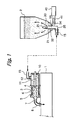
- the image forming apparatus includes a developing unit 1 and a toner container 2.
- the toner container 2 is a specific form of the powder container and stores powdery toner therein.
- the toner container 2 is implemented as a bag-in-box type container made up of a deformable bag or toner storing body 20 and a box 50 accommodating the bag 20.
- the box 50 is more rigid than the bag 20.
- the toner container 2 is a unit separate from the developing unit 1 and removably mounted to a mount portion included in the body of the apparatus from above the apparatus.
- the mount portion may be positioned within the apparatus such that it is accessible when, e.g., a door or a cover mounted on the apparatus body is opened. Alternatively, the mount portion may be arranged on the outside of the apparatus body, if desired.
- the mount portion includes an upright nozzle 30 capable of penetrating into the toner container 2 when the container is set.
- the nozzle 30 has a conical tip member 31 molded integrally with, adhered to or otherwise mounted on its top.
- the nozzle has a double-tube structure defining an air inlet passage 32 and a toner outlet passage 33, which are contiguous with the tip member 31.
- the toner outlet passage 33 is bent to the left, as viewed in FIG. 1, at the bottom of the nozzle 30 and formed with an opening 35 at its end.
- the air inlet passage 32 is bent to the right, as viewed in FIG. 1, at a level higher than the toner outlet passage 33 and formed with an opening 34 at its end.
- the opening 34 of the air inlet passage 32 is in communication with an air pump or air feeding means 40 by a pipe 41.
- the air pump 40 delivers air under pressure into the toner container 2 via the pipe 41 and air inlet passage 32. Air jetted into the toner container 2 flows through a toner layer and fluidizes the toner layer by scattering it.
- a suction type powder pump 3 is located in the vicinity of or constructed integrally with the developing unit 1.
- the powder pump 3 is a single axis, eccentric screw pump and made up of a rotor 4, a stator 5 and a holder 6.
- the rotor 4 is made of metal or similar rigid material and is provided with an eccentric, screw-like configuration.
- the stator 5 is formed of rubber or similar elastic material and is provided with a double-screw configuration.
- the holder 6 accommodates the rotor 4 and stator 5 therein in such a manner as to form a toner passage and is formed of, e.g., resin.
- a toner outlet 7 is formed at the left end of the holder 6, as viewed in FIG. 1.
- a pipe 8 provides fluid communication between the toner outlet 7 and a toner inlet, not shown, formed in the developing unit 1.
- a buffer or toner storing means 10 is connected to the inlet side of the powder pump 3 in order to store an adequate amount of toner.
- a screw or toner conveying means 11 is disposed in the buffer 10 and protrudes to the outside of the buffer 10 at one end.
- a drive source, not shown, is drivably connected to the protruding end of the screw 11.
- the other end of the screw 11 is connected to the rotor 4. In this configuration, the powder pump 3 and screw 11 can be operated of at the same time.
- a toner inlet 12 is formed in the buffer 10.
- a flexible tube 15 communicates the toner inlet 12 to the opening 35 of the nozzle 30.
- the tube 15 has a diameter of, e.g., 4 mm to 10 mm and is formed of polyurethane, nitril, EPDM, silicone or similar rubber highly resistant to toner.
- the tube 15 with flexibility can be easily laid in any desired direction, i.e., upward, downward, rightward or leftward.
- the powder pump or screw pump 3 can continuously deliver toner with a high solid-to-gas ratio by an accurate, constant amount, which is proportional to the rotation speed of the rotor 4, as well known in the art.
- the powder pump 3 In response to a replenishment command derived from, e.g., sensed image density, the powder pump 3 is operated to replenish a required amount of toner to the developing unit 1.
- FIG. 4 shows another specific configuration of the toner replenishing device.
- This toner replenishing device differs from the device shown in FIG. 1 in that the buffer 10 is absent, and in that the nozzle 30 has a single wall structure.
- structural elements identical with the structural elements shown in FIG. 1 are designated by identical reference numerals, and a detailed description thereof will not be made in order to avoid redundancy.
- the nozzle 30 is a straight, cylindrical tube in which an air inlet/toner outlet passage 33 is formed.
- the passage 33 is in communication with the tip member 31.
- the passage 33 is bent to the left, as viewed in FIG. 4, at the bottom of the nozzle 30 and terminates at the opening 35.
- the tube 15 is connected to the opening 35.
- the passage 33 is bent to the right, as viewed in FIG. 4, at a level higher than the opening 35 and terminates at the opening 34.
- the bag or toner storing body 20 is made up of a mouth member 21 and a bag 22 affixed to the mouth member 21.
- the mouth member 21 is formed of, e.g., resin by blow molding or similar technology and includes a toner outlet.
- the bag 22 is-implemented by a flexible sheet or a laminate of flexible sheets formed of polyethylene, nylon or similar resin and 80 ⁇ m to 200 ⁇ m thick each.
- the bag 20 is provided with filters 28 at its side substantially opposite to the side where the mouth member 21 is positioned. The filters 28 pass air therethrough, but does not pass toner.
- the mouth member 21 includes a through hole 24 extending in the up-and-down direction and forming the toner outlet.
- a flat slider 25 is affixed to or formed integrally with the outer periphery of the wall that forms the through hole 24.
- the slider 25 is generally rectangular and constitutes projections forming part of connecting means.
- the flexible bag 22 is affixed to a boat-shaped protuberance 26, which is also included in the mouth member 21 above the slider 25.
- An outlet portion 27 is positioned below the slider 25 and forms the through hole 24.
- a seal valve or self-closing valve 23 is fitted in the outlet portion 27 and formed of an elastic material, preferably foam sponge.
- a cap 70 is formed integrally with the mouth member 21 via a connecting portion 74 in order to close the outlet portion 27.
- a circular recess 71 is formed in the cap 70 and capable of mating with the outlet portion 27.
- the connecting portion 74 has a length, as measured in the connecting direction, substantially equal to the height of the outlet portion 27.
- generally V-shaped grooves 75 are formed in the opposite ends of the connecting portion 74 in the direction of connection.
- the cap 70, mouth member 21 and connecting portion 74 may be implemented as a single molding of resin.
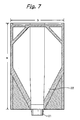
- FIG. 7 is a front view showing a specific configuration of the bag 20 in a position just after production and not packed with toner.
- the bag 20 appears as shown in FIG. 3.
- the bag 20 has a height a and a width b.
- the height a and width b are selected to be about 185 mm and about 113 mm, respectively.
- the bag 20 has a depth c (see FIG. 3) selected to be about 63 mm. With such dimensions, the bag 20 is capable of accommodating about 300 grams of toner.
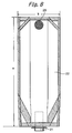
- FIG. 8 shows other specific dimensions of the bag 20.
- the bag 20 has a height a of about 305 mm, a width b of about 113 mm, and a depth c of about 55mm and can accommodate about 600 grams of toner.
- the filters 28 each has a diameter of 1.75 cm, an area of about 2.4 cm 2 , and air permeability of 2 to 7 ml/cm 2 .sec x 2.4 cm 2 , i.e., 4.8 to 16.8 ml/sec.
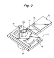
- FIG. 9 shows another specific configuration of the mouth member 21.
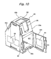
- the mouth member 21 is formed with pockets 76 that serve as means for connecting the mouth member 21 to a box 80 shown in FIG. 10.
- a generally rectangular opening is formed in the upper portion of the box 80.
- the opposite edges of this opening, which form lugs, and the pockets 76 of the mouth member 21 mate with each other, connecting the mouth member 21 to the box 80.
- the mouth member 21 of FIG. 9 is identical with the mouth member of FIG. 5.
- the cap 70, mouth member 21 and connecting portion 74 are implemented as a single molding of resin.
- FIG. 11 shows a specific configuration of the box 80 shown in FIG. 10 in a developed view.
- the box 80 has eight walls 80a through 80h.
- the walls 80a through 80h have straight sides contiguous with each other and straight sides separate from each other, and each has at least one side contiguous with the side of the adjoining wall. Therefore, by suitably selecting the contiguous sides and separate sides of the walls 80a through 80h, it is possible to develop the box 80 in the form of a single sheet having any one of various shapes.
- the contiguous sides prevent the walls 80a through 80h from fully parting from each other at the time of development.
- a V-shaped groove 81 is formed in each of the contiguous sides of the walls 80a through 80h in order to limit a foldable angle.
- the angle of the letter V is selected in accordance with the angle by which each contiguous side is to be folded. For example, when the angle of the letter V is 90 degrees, nearby walls contiguous with each other via the groove 81 can be folded by substantially 90 degrees in the direction in which the surfaces forming the letter V contact each other. On the other hand, the nearby walls can be folded up to contact each other when folded in the other direction in which the surfaces forming the letter V move away from each other.
- tongues 82 protrude from one of the adjoining separate edges of the walls 80a through 80h.
- Holes 83 are formed in the other of the adjoining separate edges of the walls 80a through 80h.
- the tongues 82 and holes 83 mate with each other and constitute fastening means for fastening nearby walls 80a through 80h.
- the walls 80a through 80h in the form of a flat sheet are folded inward in a suitable sequence with the tongues 82 mating with the holes 83.
- the box 80 can therefore be framed without resorting to any tool.
- the wall 80d of the box 80 is rectangular and continuous with the walls 80c and 80e in the up-and-down direction and contiguous with the walls 80a and 80f in the right-and-left direction and therefore does not have any separate side.
- the walls 80a and 80f each have a trapezoidal top.
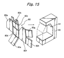
- a jig 90 formed with a cavity 91.
- the cavity 91 is configured such that the wall 80d is located at the deepest position in the cavity 91 while the walls 80b, 80c and 80e, which are contiguous with the wall 80d in the up-and-down direction, are so angled as to form part of the box 80.
- the trapezoidal walls 80a and 80b protrude from the opposite sides of the cavity 91.
- the walls 80a and 80f are folded upward to complete the box 80.
- the walls 80h and 80g are respectively contiguous with the straight side and inclined side of the wall 80f. These walls 80h and 80g are left open during assembly and closed after the insertion of the bag 20 into the box 80.
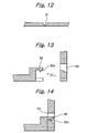
- each tongue 82 has a tapered end 82a.
- the tapered end 82a abuts against the edge of the associated hole 83 and thereby causes the tongue 82 to elastically deform for a moment, so that the walls are fastened to each other.
- rollers 92 may be moved along the opposite sides of the jig 90 in a direction in which the walls 80a and 80f fold upward. This easily implements automatic assembly of the box 80.
- the bag 20 packed with toner is fitted to the box 80 by the following procedure. Because the walls 80g and 80h of the box 80 are left open, the mouth member 21 is slid into the box 80 with its pockets 76 mating with the edges or lugs 88 of the rectangular opening of the box 80. Subsequently, the walls 80g and 80h are closed with their tongues 82 mating with the holes 83 of the wall 80a, fully assembling the toner container 2.
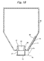
- the bag 20 has its outlet portion 27 closed by the cap 70 in order to prevent the toner from leaking during, e.g., assembly, as indicated by a dash-and-dots line in FIG. 18.
- a seal 60 may be wrapped around all the side surfaces of the toner container 2.
- the seal 60 may be implemented by a thermally shrinkable seal by way of example. Further, the seal 60 may be provided with a shrink wrap 61 in order to allow the box 80 to be easily unfolded by hand. As shown in FIG. 20, the seal 60 may be replaced with an adhesive seal 62 adhered to the walls 80g and 80h folded last and the wall 80a.
- the wall 80g is formed with a fitting portion 85 for fitting the cap 70.
- the cap 70 is removed from the outlet portion 27 and then fitted in the fitting portion 85, as indicated by a solid line in FIG. 18. This prevents the cap 70 from obstructing the operation for mounting the toner container 2 to the apparatus body. Because the wall 80g with the fitting portion 85 is closed last together with the wall 80h, the cap 70 received in the fitting portion 85 is prevented from moving and is firmly connected to the box 80.
- the toner container 2 set on the apparatus body runs out of toner, it is picked up from the apparatus body.
- the walls 80g and 80h are unfolded or opened.
- the empty bag 20 can be easily released from the box 80.
- the box 80 can be folded up in, e.g., two in a small size and is therefore easy to transport or store while occupying a minimum of space. This noticeably reduces the cost necessary for the box 80 to be distributed from the user's station to the manufacturer's station.
- the box 80 is formed of a material having certain durability, then it can be repeatedly used a plurality of times and therefore contributes a great deal to cost reduction.
- an indication 89 showing a disassembling procedure may be suitably provided on the wall of the box 80 that opens when the seal 60 is removed.
- the indication 89 may be provided on the inside of the wall 80h. The indication 89 allows even the user to simply disassemble the box 80.
- Air is sent into the bag 20 of the toner container 2, which is mounted to the image forming apparatus, in order to replenish the toner to the developing unit 1 while fluidizing it, as stated earlier. Therefore, even when the toner container 2 run out of toner is picked up from the apparatus, some air is left in the bag 20 and maintains the bag 20 slightly inflated. Further, when the toner container 2 is removed from the nozzle 30, the seal valve 23 tends to restore its original position, but fails to restore it and cannot preserve its original sealability. On the other hand, the empty bag 20 removed from the box 80 is burned or otherwise dealt with for a reusing purpose by way of example. If the bag 20 is transported without being exhausted of air at the time of collection, the low-cost feature of the toner container 2 is canceled. However, because the seal valve 23 cannot preserve its original sealability, as stated above, pressure exerted on the bag 20 in the collapsing direction would cause the toner to fly about via the slightly open seal valve 23.
- the bag 20 is pressed in the collapsing direction after the cap 70 has been fitted on the outlet portion 27.
- air compressed within the bag 20 flows out of the bag 20 via the filters 28 that pass air, but do not pass the toner. This allows the bag 20 to be exhausted without causing the toner to fly about.
- the cap 70 is connected to the bag 20 and therefore prevented from being lost.
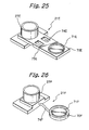
- FIGS. 21 through 26 each shows a specific modification of the mouth member 21.
- a cap 70A is connected to a mouth member 21A by a flat, thin connecting portion 74A.
- a cap 70B is connected to a mouth member 21B by a connecting portion 74B; hinges 75B are a substitute for the V-shaped grooves and determine the previously stated folding position at the time of closing.
- an adhesive tape 75C extends from a mouth member 21C to a cap 70C via a connecting portion 74C.
- a mouth member 21D includes hinges 75D in place of the V-shaped grooves.
- the hinges 75D connect a cap 71D to the mouth member 21D via a connecting portion 74D and determine the folding position at the time of closing.
- a mouth member 21E has a connecting portion 74E and a cap 70E molded integrally with each other as in the illustrative embodiment. While the mouth member 21E determines the folding position by using a V-shaped groove 75E, it is formed with suitable openings in order to reduce the amount of material without lowering mechanical strength.
- a cap 80F is connected to a mouth member 21F by a string-like connecting means 74F.
- the bag 20 of the toner container 2 is flexible while the box 50 or 80 can be folded up in a small size or developed in the form of a flat sheet.
- the toner container 2 is therefore easy to handle at the time of transport or storage while saving space, compared to a hard case.
- the bag 20 is collected by the manufacturer and then recycled, reused or burned.
- the box 50 or 80 with the above advantages noticeably reduces the cost necessary for the collection and distribution thereof.
- the mouth member 21, bag portion 22 and seal valve 23 of the bag 20 should preferably be formed of the same material or materials belonging to the same series, so that they do not have to be classified at the time of recycling.
- the present invention achieves various unprecedented advantages, as enumerated below.
Landscapes
- Physics & Mathematics (AREA)
- General Physics & Mathematics (AREA)
- Engineering & Computer Science (AREA)
- Mechanical Engineering (AREA)
- Dry Development In Electrophotography (AREA)
- Packages (AREA)
- Bag Frames (AREA)
Claims (21)
- Récipient pour poudre comprenant :caractérisé en ce queun corps de stockage de poudre déformable (20) pour stocker la poudre à l'intérieur, une partie de sortie de poudre (27) étant comprise dans ledit corps de stockage de poudre ; etune boíte (50, 80) plus rigide que ledit corps de stockage de poudre déformable pour loger ledit corps de stockage de poudre ;ladite partie de sortie de poudre (27) est configurée de façon à se montrer partiellement au niveau d'une partie extérieure de ladite boíte lorsque le corps de stockage de poudre (20) est logé dans ladite boíte (50, 80) ;un clapet se refermant automatiquement (23) est prévu, lequel est adapté dans ladite partie de sortie de poudre et configuré pour une ouverture lorsqu'un élément d'insertion (31) est inséré ou pour une fermeture lorsque ledit élément d'insertion (31) est retiré ; etun moyen de fermeture (70) est prévu de façon à être attaché de façon amovible à ladite partie de sortie de poudre (27) pour fermer ledit clapet se refermant automatiquement.
- Récipient pour poudre tel que revendiqué dans la revendication 1, comprenant en outre un élément d'embouchure (21) monté sur ledit corps de stockage de poudre et formé avec ladite partie de sortie de poudre (27), dans lequel ledit clapet se refermant automatiquement (23) est adapté dans ledit élément d'embouchure.
- Récipient pour poudre tel que revendiqué dans les revendications 1 ou 2, dans lequel ledit élément d'insertion (31) comprend une buse (30) dans laquelle un passage pour la poudre (33) est formé.
- Récipient pour poudre tel que revendiqué dans les revendications 1, 2 ou 3, dans lequel ledit moyen de fermeture (70), ledit élément d'embouchure (21) et une partie de raccordement (74) raccordant ledit moyen de fermeture audit élément d'embouchure sont formés de résine et moulés intégralement les uns avec les autres.
- Récipient pour poudre tel que revendiqué dans les revendications 1, 2, 3 ou 4, comprenant en outre une partie d'ajustage (85) comprise dans ladite boíte pour ajuster ledit moyen de fermeture (70) lorsque ledit moyen de fermeture est enlevé de ladite partie de sortie de poudre.
- Récipient pour poudre tel que revendiqué dans la revendication 5, dans lequel ledit moyen de fermeture (70) enlevé de ladite partie de sortie de toner et ladite partie de raccordement (74) sont ajustés dans ladite partie d'ajustage (85).
- Récipient pour poudre tel que revendiqué dans les revendications 5 ou 6, comprenant en outre une partie d'ouverture/fermeture comprise dans ladite boíte et pouvant être ouverte lorsque ledit corps de stockage de poudre doit être inséré dans ladite boíte, ladite partie d'ajustage étant formée sur ladite partie d'ouverture/fermeture.
- Récipient pour poudre tel que revendiqué dans l'une des revendications précédentes, dans lequel ledit moyen de fermeture comprend un capuchon fixé de façon amovible sur ladite partie de sortie de poudre.
- Récipient pour poudre tel que revendiqué dans l'une des revendications précédentes, dans lequel ledit moyen de fermeture est raccordé audit corps de stockage de poudre.
- Récipient pour poudre tel que revendiqué dans l'une des revendications précédentes, comprenant en outre un élément d'embouchure monté sur ledit corps de stockage de poudre et formé avec ladite partie de sortie de poudre, ledit moyen de fermeture étant raccordé au niveau d'une de ses extrémités audit élément d'embouchure via une partie de raccordement (74).
- Récipient pour poudre tel que revendiqué dans les revendications 4 ou 10, dans lequel ladite partie de raccordement est formée avec des rainures au voisinage de ses extrémités opposées pour un raccordement afin de déterminer des positions de pliage.
- Récipient pour poudre selon l'une quelconque des revendications précédentes, comprenant en outre :une partie d'échappement (28) comprise dans ledit corps de stockage de poudre pour faire s'échapper l'air dudit corps de stockage de poudre tout en filtrant la poudre.
- Récipient pour poudre tel que revendiqué dans la revendication 12, dans lequel ladite partie d'échappement comprend un filtre qui laisse passer l'air à travers lui mais qui ne laisse pas passer la poudre.
- Récipient pour poudre selon l'une quelconque des revendications précédentes, dans lequel ladite boíte (50, 80) est polyèdre et
dans lequel les parois de ladite boíte ont chacune un côté contigu qui est contigu à une paroi adjacente et un côté séparé et sont aptes à être développées sous la forme d'une feuille unique. - Récipient pour poudre tel que revendiqué dans la revendication 14, dans lequel lesdites parois . sont rectangulaires tandis que l'une desdites parois a quatre côtés contigus à la fois suivant une direction de haut en bas et suivant une direction de droite à gauche.
- Procédé de construction d'une boíte comprise dans un récipient pour poudre (2) selon l'une quelconque des revendications précédentes, ledit procédé comprenant les étapes consistant à :préparer la boíte développée sous la forme d'une feuille unique et ayant des parois rectangulaires dont chacune a un côté contigu qui est contigu à une paroi adjacente et un côté séparé, dans lequel l'une desdites parois a quatre côtés contigus à la fois suivant une direction de haut en bas et suivant une direction de droite à gauche ;positionner la boíte dans un gabarit (90) de telle sorte que les parois contiguës à la paroi qui est dans la direction de haut en bas soient pliées selon un angle qui forme une boíte ; etplier les parois contiguës à la paroi qui est dans la direction de droite à gauche de telle sorte que lesdites parois rencontrent les parois contiguës à la paroi qui est dans la direction de haut en bas.
- Procédé tel que revendiqué dans la revendication 16, dans lequel ledit gabarit (90) présente une largeur suivant la direction de droite à gauche qui est sensiblement égale ou inférieure à une largeur de la paroi qui est suivant la direction de droite à gauche.
- Procédé tel que revendiqué dans les revendications 16 ou 17, dans lequel, après que la boíte a été positionnée dans le gabarit de telle sorte que les parois contiguës à la paroi qui est dans la direction de haut en bas soient pliées selon l'angle qui forme une boíte, des corps amovibles (92) sont amenés à se déplacer le long de côtés opposés du gabarit (90), moyennant quoi les parois contiguës à la paroi qui est suivant la direction de droite à gauche sont pliées vers le haut.
- Procédé tel que revendiqué dans les revendications 16, 17 ou 18, dans lequel la paroi qui est destinée à faire face à la paroi est contiguë à l'une des parois contiguës à ladite paroi qui est suivant la direction de droite à gauche et forme une partie d'ouverture/fermeture.
- Procédé de réduction d'un volume d'un corps de stockage de poudre déformable (20) compris dans un récipient pour poudre (2) selon l'une quelconque des revendications 1 à 15, procédé dans lequel, après avoir quasiment totalement déchargé ladite poudre dudit récipient pour poudre, les étapes suivantes sont exécutées :la fermeture d'une partie de sortie de poudre comprise dans le corps de stockage de poudre grâce à un moyen de fermeture ; etla pression du corps de stockage de poudre suivant une direction dans laquelle ledit corps de stockage de poudre s'affaisse, moyennant quoi l'air s'échappe dudit corps de stockage de poudre.
- Procédé tel que revendiqué dans la revendication 20, dans lequel le corps de stockage de poudre stocke du toner et comprend une partie d'échappement réalisée au moyen d'un filtre qui laisse passer l'air à travers lui mais qui ne laisse pas passer ledit toner.
Applications Claiming Priority (4)
| Application Number | Priority Date | Filing Date | Title |
|---|---|---|---|
| JP2000053583 | 2000-02-29 | ||
| JP2000053583 | 2000-02-29 | ||
| JP2001009310A JP3967078B2 (ja) | 2000-02-29 | 2001-01-17 | 粉体収納容器および該容器の組み立て方法 |
| JP2001009310 | 2001-01-17 |
Publications (3)
| Publication Number | Publication Date |
|---|---|
| EP1129961A2 EP1129961A2 (fr) | 2001-09-05 |
| EP1129961A3 EP1129961A3 (fr) | 2002-01-16 |
| EP1129961B1 true EP1129961B1 (fr) | 2003-07-30 |
Family
ID=26586369
Family Applications (1)
| Application Number | Title | Priority Date | Filing Date |
|---|---|---|---|
| EP01104464A Expired - Lifetime EP1129961B1 (fr) | 2000-02-29 | 2001-02-28 | Récipient pour poudre, procédé pour l'assembler et procédé pour réduire son volume |
Country Status (10)
| Country | Link |
|---|---|
| US (1) | US6519436B2 (fr) |
| EP (1) | EP1129961B1 (fr) |
| JP (1) | JP3967078B2 (fr) |
| KR (1) | KR100392752B1 (fr) |
| CN (2) | CN1222841C (fr) |
| DE (1) | DE60100513T2 (fr) |
| ES (1) | ES2202232T3 (fr) |
| MX (1) | MXPA01002115A (fr) |
| MY (1) | MY116611A (fr) |
| SG (1) | SG115365A1 (fr) |
Families Citing this family (44)
| Publication number | Priority date | Publication date | Assignee | Title |
|---|---|---|---|---|
| JP4157681B2 (ja) * | 2000-02-14 | 2008-10-01 | 株式会社リコー | トナー収納容器 |
| JP4194254B2 (ja) * | 2000-06-22 | 2008-12-10 | 株式会社リコー | トナー収納容器および画像形成装置 |
| JP2003048631A (ja) | 2001-05-31 | 2003-02-21 | Ricoh Co Ltd | 多目的収納テーブル |
| JP2003234887A (ja) | 2002-02-08 | 2003-08-22 | Ricoh Co Ltd | 画像形成方法、画像形成装置、コンピュータプログラムおよび記憶媒体 |
| US7542703B2 (en) * | 2002-05-20 | 2009-06-02 | Ricoh Company, Ltd. | Developing device replenishing a toner or a carrier of a two-ingredient type developer and image forming apparatus including the developing device |
| WO2004027522A1 (fr) | 2002-09-20 | 2004-04-01 | Ricoh Company, Limited | Dispositif de formation d'images, dispositif d'alimentation en energie, contenant de stockage de toner, contenant de stockage de poudre, et procede de recyclage des contenants |
| JP4220798B2 (ja) * | 2002-09-20 | 2009-02-04 | 株式会社リコー | 粉体収納容器 |
| US7116928B2 (en) | 2002-12-18 | 2006-10-03 | Ricoh Company, Ltd. | Powder discharging device and image forming apparatus using the same |
| GB0314815D0 (en) | 2003-06-25 | 2003-07-30 | Stephenson John | Bag in box |
| JP4584659B2 (ja) * | 2003-09-30 | 2010-11-24 | 株式会社リコー | 画像形成用粉体を内包する易変形性容器用容器収納箱 |
| TR200400168A2 (tr) * | 2004-01-29 | 2005-09-21 | Sunj�T Sun� J�T Sanay� Ve T�Caret Anon�M ��Rket� | Büyük çuval boşaltma bacası koruma tertibatı |
| JP4343074B2 (ja) * | 2004-03-19 | 2009-10-14 | 株式会社リコー | 容器収納装置、該容器収納装置を備えた搬送装置及び画像形成装置 |
| EP1589384B1 (fr) * | 2004-04-23 | 2020-01-08 | Ricoh Company, Ltd. | Récipient de développateur |
| JP2006039424A (ja) * | 2004-07-29 | 2006-02-09 | Ricoh Co Ltd | 画像形成装置及びこれに用いるトナー並びに該トナーを収納したトナー容器 |
| JP4713295B2 (ja) * | 2004-11-09 | 2011-06-29 | 株式会社リコー | 減容装置及びトナー補給装置 |
| DE102007025387A1 (de) * | 2007-05-30 | 2008-12-04 | Braun Gmbh | Nachfüllpack für ein Gerät des persönlichen Bedarfs |
| JP5015669B2 (ja) * | 2007-06-20 | 2012-08-29 | 株式会社リコー | 画像読取装置、画像形成装置、電子ペーパーおよびプログラム |
| US8720769B2 (en) | 2009-09-15 | 2014-05-13 | Packaging Corporation Of America | Beverage container |
| US9415997B2 (en) * | 2012-04-26 | 2016-08-16 | Southern Champion Tray | Bottle in box container |
| JP5420024B2 (ja) * | 2011-07-14 | 2014-02-19 | キヤノン株式会社 | 現像剤収納容器、現像剤収納ユニット、プロセスカートリッジ、電子写真画像形成装置 |
| JP5668653B2 (ja) * | 2011-09-16 | 2015-02-12 | コニカミノルタ株式会社 | 粉体収容装置 |
| KR101956851B1 (ko) * | 2011-11-25 | 2019-03-12 | 가부시키가이샤 리코 | 분체 수납 용기 및 화상 형성 장치 |
| JP6019799B2 (ja) * | 2012-06-22 | 2016-11-02 | 株式会社リコー | トナー補給容器 |
| CN107529427A (zh) * | 2013-05-10 | 2018-01-02 | 竹斯柔公司 | 榨汁系统 |
| US9580224B2 (en) * | 2014-01-30 | 2017-02-28 | Sonoco Development, Inc. | Composite container with internal fitment |
| CN104298095A (zh) * | 2014-11-03 | 2015-01-21 | 合肥万合科技信息服务有限公司 | 一种打印机用加粉装置 |
| US20170252991A1 (en) * | 2016-03-03 | 2017-09-07 | Juicero, Inc. | Juicer with flexible seal |
| US20170252996A1 (en) * | 2016-03-03 | 2017-09-07 | Juicero, Inc. | Juicer cartridge with secondary flow channel |
| US20170253000A1 (en) * | 2016-03-03 | 2017-09-07 | Juicero, Inc. | Juicer with locking mechanism |
| US20170252999A1 (en) * | 2016-03-03 | 2017-09-07 | Juicero, Inc. | Juicer with juicer cartridge orientation feature |
| US20170252997A1 (en) * | 2016-03-03 | 2017-09-07 | Juicero, Inc. | Juicer cartridge with sanitary seal |
| US20170252994A1 (en) * | 2016-03-03 | 2017-09-07 | Juicero, Inc. | Juicing system with juicer cartridge restraints |
| US20170252993A1 (en) * | 2016-03-03 | 2017-09-07 | Juicero, Inc. | Juicer cartridge with coupling |
| US20170252995A1 (en) * | 2016-03-03 | 2017-09-07 | Juicero, Inc. | Juicer cartridge with outlet separator |
| US20170252998A1 (en) * | 2016-03-03 | 2017-09-07 | Juicero, Inc. | Juicer cartridge with flow disruptor |
| US20170251863A1 (en) * | 2016-03-03 | 2017-09-07 | Juicero, Inc. | Angled juicing system |
| US20170252990A1 (en) * | 2016-03-03 | 2017-09-07 | Juicero, Inc. | Juicer cartridge geometry |
| KR102171904B1 (ko) * | 2016-05-12 | 2020-11-02 | 휴렛-팩커드 디벨롭먼트 컴퍼니, 엘.피. | 축조 재료 용기 |
| EP3434448A1 (fr) * | 2017-07-28 | 2019-01-30 | Hewlett-Packard Development Company, L.P. | Contenant de matériau de construction |
| ES2884057T3 (es) * | 2017-07-28 | 2021-12-10 | Hewlett Packard Development Co | Contenedor para material de construcción |
| US10919680B1 (en) | 2018-10-08 | 2021-02-16 | Packaging Corporation Of America | Liquid beverage container |
| CN117908344A (zh) * | 2019-08-09 | 2024-04-19 | 佳能株式会社 | 调色剂容器 |
| WO2023105981A1 (fr) * | 2021-12-06 | 2023-06-15 | キヤノン株式会社 | Récipient de toner et système de formation d'image |
| JP7764238B2 (ja) * | 2021-12-23 | 2025-11-05 | キヤノン株式会社 | 現像剤容器および画像形成システム |
Family Cites Families (25)
| Publication number | Priority date | Publication date | Assignee | Title |
|---|---|---|---|---|
| JPS6080878A (ja) * | 1983-10-08 | 1985-05-08 | Olympus Optical Co Ltd | トナ−カ−トリツジ |
| JPH01120587A (ja) * | 1987-11-04 | 1989-05-12 | Fukuda Metal Foil & Powder Co Ltd | トナー容器 |
| JPH01119536A (ja) * | 1987-11-04 | 1989-05-11 | Canon Inc | プリフォーム形成方法 |
| JPH01255877A (ja) * | 1988-04-06 | 1989-10-12 | Ricoh Co Ltd | 複写機の現像装置 |
| EP0358053B1 (fr) * | 1988-09-08 | 1995-07-19 | Sotralentz S.A. | Récipient pour le stockage et le transport de produits liquides ou pulvérulents |
| US6155457A (en) * | 1991-03-26 | 2000-12-05 | Indigo N.V. | Dispenser apparatus especially for liquid toner concentrate |
| JPH06244031A (ja) | 1993-02-22 | 1994-09-02 | Matsushita Electric Ind Co Ltd | 可変インダクタ調整装置 |
| JPH06274031A (ja) * | 1993-03-23 | 1994-09-30 | Tokyo Electric Co Ltd | 電子写真装置のトナー補給装置 |
| US5348186A (en) * | 1993-04-02 | 1994-09-20 | Longview Fibre Company | Paperboard container for fluids having top opening fitment and exposed lip for engagement by handling implements |
| JP3225136B2 (ja) * | 1993-07-31 | 2001-11-05 | 花王株式会社 | トナー補給用治具およびトナーカートリッジ |
| EP0704309A3 (fr) * | 1994-09-29 | 1998-01-07 | Hewlett-Packard Company | Procédé et système pour la régulation du système de réapprovisionnement en encre d'une cartoucle d'impression |
| JP2685002B2 (ja) * | 1994-11-11 | 1997-12-03 | 日本電気株式会社 | 電子写真装置のトナー補給機構 |
| TW367297B (en) * | 1994-11-18 | 1999-08-21 | Hosokawa Yoko Kk | Bag for bag-in-box and bag-in-box |
| JP3326582B2 (ja) * | 1995-06-15 | 2002-09-24 | 京セラミタ株式会社 | 現像剤補給装置 |
| US5655179A (en) * | 1995-06-15 | 1997-08-05 | Mita Industrial Co., Ltd. | Developer replenishing apparatus having engaging mechanisms for preventing toner scatter during toner replenishment |
| JP3437332B2 (ja) * | 1995-07-10 | 2003-08-18 | キヤノン株式会社 | 粉体供給用容器と該粉体供給用容器の製造方法及び粉体供給方法 |
| DE69733800T2 (de) * | 1996-12-24 | 2006-04-06 | Mixpac Systems Ag | Vorrichtung und Kartusche für einen umstülpbaren Schlauchbeutel |
| KR20010023020A (ko) | 1997-08-19 | 2001-03-26 | 가부시키가이샤 쇼와 마루쯔쯔 | 토너카트리지 및 그것의 유통구의 개폐기구 |
| ID25801A (id) * | 1997-08-21 | 2000-11-02 | Seaquist Closures | Bungkus penyalur dan metode untuk membuat bungkus penyalur |
| JPH11119536A (ja) * | 1997-10-20 | 1999-04-30 | Canon Inc | 乾式電子写真用トナーボトル |
| FR2775658B1 (fr) | 1998-03-03 | 2000-06-16 | Otor Sa | Procede et machine pour la realisation d'une caisse octogonale a coins coupes en matiere en feuille |
| JP4084457B2 (ja) * | 1998-03-31 | 2008-04-30 | 株式会社リコー | 剤収納容器および画像形成装置 |
| DE29817571U1 (de) * | 1998-10-01 | 1998-12-17 | Georg Menshen GmbH & Co KG, 57413 Finnentrop | Selbstschließende Ventilanordnung für eine Behälterspendeöffnung |
| JP3935666B2 (ja) * | 1999-09-30 | 2007-06-27 | 株式会社リコー | ノズル、トナー移送装置および画像形成装置 |
| KR100341322B1 (ko) * | 1999-11-19 | 2002-06-21 | 윤종용 | 습식 전자사진방식 칼라 인쇄기용 잉크 카트리지 |
-
2001
- 2001-01-17 JP JP2001009310A patent/JP3967078B2/ja not_active Expired - Fee Related
- 2001-02-27 MX MXPA01002115A patent/MXPA01002115A/es active IP Right Grant
- 2001-02-27 MY MYPI20010852A patent/MY116611A/en unknown
- 2001-02-27 CN CNB011083050A patent/CN1222841C/zh not_active Expired - Fee Related
- 2001-02-27 KR KR10-2001-0009939A patent/KR100392752B1/ko not_active Expired - Fee Related
- 2001-02-27 US US09/793,582 patent/US6519436B2/en not_active Expired - Lifetime
- 2001-02-27 CN CNA200410049245XA patent/CN1549061A/zh active Pending
- 2001-02-28 EP EP01104464A patent/EP1129961B1/fr not_active Expired - Lifetime
- 2001-02-28 DE DE60100513T patent/DE60100513T2/de not_active Expired - Lifetime
- 2001-02-28 ES ES01104464T patent/ES2202232T3/es not_active Expired - Lifetime
- 2001-02-28 SG SG200101269A patent/SG115365A1/en unknown
Also Published As
| Publication number | Publication date |
|---|---|
| SG115365A1 (en) | 2005-10-28 |
| US20010033758A1 (en) | 2001-10-25 |
| EP1129961A3 (fr) | 2002-01-16 |
| CN1549061A (zh) | 2004-11-24 |
| HK1037032A1 (en) | 2002-01-25 |
| CN1311461A (zh) | 2001-09-05 |
| MXPA01002115A (es) | 2002-06-04 |
| CN1222841C (zh) | 2005-10-12 |
| KR100392752B1 (ko) | 2003-07-28 |
| EP1129961A2 (fr) | 2001-09-05 |
| JP2001315851A (ja) | 2001-11-13 |
| KR20010100799A (ko) | 2001-11-14 |
| JP3967078B2 (ja) | 2007-08-29 |
| DE60100513T2 (de) | 2004-03-04 |
| DE60100513D1 (de) | 2003-09-04 |
| ES2202232T3 (es) | 2004-04-01 |
| US6519436B2 (en) | 2003-02-11 |
| MY116611A (en) | 2004-02-28 |
Similar Documents
| Publication | Publication Date | Title |
|---|---|---|
| US6519436B2 (en) | Toner powder container for storing toner applicable to an electrographic image forming apparatus, a method at assembling the same, and a method of reducing the volume of the same | |
| US6648218B2 (en) | Powder container, method of assembling the same and image forming apparatus | |
| US7389071B2 (en) | Apparatuses for image forming capable of effectively conveying developer therefrom and a method of effectively forming a reinforcing member adhering to the apparatuses | |
| EP1400869B1 (fr) | Récipient pour toner de type sac avec un obturateur | |
| EP1475674B1 (fr) | Système bag-in-box pour stocker de toner | |
| US6813460B2 (en) | Toner container and image forming apparatus using the same | |
| EP0829778A2 (fr) | Unité de traitement, récipient de développateur, récipient de développateur usé, procédé d'assemblage d'unité de traitement, procédé de remplissage de développateur dans une unité de traitement | |
| EP0822464B1 (fr) | Produit intégrant une enveloppe retour | |
| US6532352B2 (en) | Powder container and image forming apparatus using same | |
| US20040071481A1 (en) | Toner container and toner replenishing device using the same | |
| JP2002002833A (ja) | 粉体収納容器および画像形成装置 | |
| US20060038863A1 (en) | Refillable chemical cartridge for photoprocessing equipment | |
| CN100456160C (zh) | 容器保持装置、输送装置、成像设备及固定容器的方法 | |
| JP2007254007A (ja) | 梱包材、及び梱包材によって梱包された画像形成用交換ユニット | |
| HK1037032B (en) | Powder container, the assembly method thereof and the method for reducing the capacity of the container |
Legal Events
| Date | Code | Title | Description |
|---|---|---|---|
| PUAI | Public reference made under article 153(3) epc to a published international application that has entered the european phase |
Free format text: ORIGINAL CODE: 0009012 |
|
| 17P | Request for examination filed |
Effective date: 20010228 |
|
| AK | Designated contracting states |
Kind code of ref document: A2 Designated state(s): AT BE CH CY DE DK ES FI FR GB GR IE IT LI LU MC NL PT SE TR Kind code of ref document: A2 Designated state(s): DE ES FR GB IT NL |
|
| AX | Request for extension of the european patent |
Free format text: AL;LT;LV;MK;RO;SI |
|
| PUAL | Search report despatched |
Free format text: ORIGINAL CODE: 0009013 |
|
| AK | Designated contracting states |
Kind code of ref document: A3 Designated state(s): AT BE CH CY DE DK ES FI FR GB GR IE IT LI LU MC NL PT SE TR |
|
| AX | Request for extension of the european patent |
Free format text: AL;LT;LV;MK;RO;SI |
|
| 17Q | First examination report despatched |
Effective date: 20020125 |
|
| AKX | Designation fees paid |
Free format text: DE ES FR GB IT NL |
|
| GRAH | Despatch of communication of intention to grant a patent |
Free format text: ORIGINAL CODE: EPIDOS IGRA |
|
| GRAH | Despatch of communication of intention to grant a patent |
Free format text: ORIGINAL CODE: EPIDOS IGRA |
|
| GRAA | (expected) grant |
Free format text: ORIGINAL CODE: 0009210 |
|
| AK | Designated contracting states |
Designated state(s): DE ES FR GB IT NL |
|
| REG | Reference to a national code |
Ref country code: GB Ref legal event code: FG4D |
|
| REG | Reference to a national code |
Ref country code: IE Ref legal event code: FG4D |
|
| REF | Corresponds to: |
Ref document number: 60100513 Country of ref document: DE Date of ref document: 20030904 Kind code of ref document: P |
|
| REG | Reference to a national code |
Ref country code: ES Ref legal event code: FG2A Ref document number: 2202232 Country of ref document: ES Kind code of ref document: T3 |
|
| ET | Fr: translation filed | ||
| PLBE | No opposition filed within time limit |
Free format text: ORIGINAL CODE: 0009261 |
|
| STAA | Information on the status of an ep patent application or granted ep patent |
Free format text: STATUS: NO OPPOSITION FILED WITHIN TIME LIMIT |
|
| 26N | No opposition filed |
Effective date: 20040504 |
|
| REG | Reference to a national code |
Ref country code: IE Ref legal event code: MM4A |
|
| REG | Reference to a national code |
Ref country code: FR Ref legal event code: PLFP Year of fee payment: 16 |
|
| REG | Reference to a national code |
Ref country code: FR Ref legal event code: PLFP Year of fee payment: 17 |
|
| PGFP | Annual fee paid to national office [announced via postgrant information from national office to epo] |
Ref country code: DE Payment date: 20170217 Year of fee payment: 17 Ref country code: FR Payment date: 20170217 Year of fee payment: 17 |
|
| PGFP | Annual fee paid to national office [announced via postgrant information from national office to epo] |
Ref country code: NL Payment date: 20170216 Year of fee payment: 17 Ref country code: GB Payment date: 20170216 Year of fee payment: 17 |
|
| PGFP | Annual fee paid to national office [announced via postgrant information from national office to epo] |
Ref country code: ES Payment date: 20170213 Year of fee payment: 17 Ref country code: IT Payment date: 20170221 Year of fee payment: 17 |
|
| REG | Reference to a national code |
Ref country code: DE Ref legal event code: R119 Ref document number: 60100513 Country of ref document: DE |
|
| REG | Reference to a national code |
Ref country code: NL Ref legal event code: MM Effective date: 20180301 |
|
| GBPC | Gb: european patent ceased through non-payment of renewal fee |
Effective date: 20180228 |
|
| REG | Reference to a national code |
Ref country code: FR Ref legal event code: ST Effective date: 20181031 |
|
| PG25 | Lapsed in a contracting state [announced via postgrant information from national office to epo] |
Ref country code: NL Free format text: LAPSE BECAUSE OF NON-PAYMENT OF DUE FEES Effective date: 20180301 |
|
| PG25 | Lapsed in a contracting state [announced via postgrant information from national office to epo] |
Ref country code: DE Free format text: LAPSE BECAUSE OF NON-PAYMENT OF DUE FEES Effective date: 20180901 |
|
| PG25 | Lapsed in a contracting state [announced via postgrant information from national office to epo] |
Ref country code: GB Free format text: LAPSE BECAUSE OF NON-PAYMENT OF DUE FEES Effective date: 20180228 Ref country code: FR Free format text: LAPSE BECAUSE OF NON-PAYMENT OF DUE FEES Effective date: 20180228 Ref country code: IT Free format text: LAPSE BECAUSE OF NON-PAYMENT OF DUE FEES Effective date: 20180228 |
|
| REG | Reference to a national code |
Ref country code: ES Ref legal event code: FD2A Effective date: 20190801 |
|
| PG25 | Lapsed in a contracting state [announced via postgrant information from national office to epo] |
Ref country code: ES Free format text: LAPSE BECAUSE OF NON-PAYMENT OF DUE FEES Effective date: 20180301 |