EP1130164B1 - Gleisunterstopfaggregat - Google Patents
Gleisunterstopfaggregat Download PDFInfo
- Publication number
- EP1130164B1 EP1130164B1 EP01420051A EP01420051A EP1130164B1 EP 1130164 B1 EP1130164 B1 EP 1130164B1 EP 01420051 A EP01420051 A EP 01420051A EP 01420051 A EP01420051 A EP 01420051A EP 1130164 B1 EP1130164 B1 EP 1130164B1
- Authority
- EP
- European Patent Office
- Prior art keywords
- actuator
- compacting
- hydraulic
- metering
- tamping unit
- Prior art date
- Legal status (The legal status is an assumption and is not a legal conclusion. Google has not performed a legal analysis and makes no representation as to the accuracy of the status listed.)
- Expired - Lifetime
Links
- 239000012530 fluid Substances 0.000 claims abstract description 19
- 241001669679 Eleotris Species 0.000 claims description 4
- 238000006073 displacement reaction Methods 0.000 claims description 4
- 238000004891 communication Methods 0.000 claims description 2
- 230000035939 shock Effects 0.000 description 5
- 230000000903 blocking effect Effects 0.000 description 2
- 238000010586 diagram Methods 0.000 description 2
- 230000006870 function Effects 0.000 description 2
- 238000000034 method Methods 0.000 description 2
- 239000000725 suspension Substances 0.000 description 2
- 240000008042 Zea mays Species 0.000 description 1
- 238000001514 detection method Methods 0.000 description 1
- 230000000694 effects Effects 0.000 description 1
- 230000005284 excitation Effects 0.000 description 1
- 230000008571 general function Effects 0.000 description 1
Images


Classifications
-
- E—FIXED CONSTRUCTIONS
- E01—CONSTRUCTION OF ROADS, RAILWAYS, OR BRIDGES
- E01B—PERMANENT WAY; PERMANENT-WAY TOOLS; MACHINES FOR MAKING RAILWAYS OF ALL KINDS
- E01B27/00—Placing, renewing, working, cleaning, or taking-up the ballast, with or without concurrent work on the track; Devices therefor; Packing sleepers
- E01B27/12—Packing sleepers, with or without concurrent work on the track; Compacting track-carrying ballast
- E01B27/13—Packing sleepers, with or without concurrent work on the track
- E01B27/16—Sleeper-tamping machines
Definitions
- the present invention relates to a ballast tamping unit of railway tracks, of the forced vibration type.
- tamping In the railway sector, it is necessary to consolidate the tracks by blocking the sleepers by a process called tamping. This consists in making the ballast penetrate under the sleepers, by means of devices called tamping units, which are actually vibrating clamps. These are forced into the ballast, on either side of a sleeper, in making them vibrate at a determined frequency close to the natural frequency ballast, and using a clamp to force closing movement the nesting of the ballast under the sleeper.
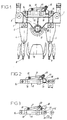
- FIG. 1 of the accompanying schematic drawing shows a unit of stuffing of current design.
- This includes a chassis 1 provided vertical suspension elements 2 and 3, and two tool holders 4 and 5 symmetrically articulated on the chassis 1 around two respective axes 6 and 7, parallel and horizontal, in the manner of levers.
- the two tool holders 4 and 5 are respectively equipped, in their upper parts, with tools 8 and 9 called “tampers", which take place on either side of a cross 10 of the way.
- An eccentric device 11, carried by the central part of the chassis 1, ensures the vibration of tools 8 and 9.
- the design general knowledge of this machine is known, for example, from the demand for patent FR 2666357 A in the name of the Applicant.
- the respective upper ends of the two tool holders 4 and 5 are joined by a hydraulic clamping cylinder 12, substantially horizontal, the body 13 of the jack 12 being for example linked by a articulation 14 to the first tool holder 4, while the rod 15 of this jack 12 is linked by a hinge 16 to the second tool holder 5.
- the hydraulic clamping cylinder 12 is usually associated with an auxiliary hydraulic cylinder 17 which, in combination with a jumper tilting 18, acts as a mechanical stroke limiter for the cylinder tightening 12, as shown more particularly in FIGS. 2 and 3.
- the auxiliary cylinder 17 is articulated by its body, around an axis 19, on the body 13 of the clamping cylinder 12, towards one end of this body 13.
- the auxiliary cylinder rod 17 is articulated about an axis 20 on the rider 18 which is itself pivotally mounted about an axis 21 on the body 13 of the clamping cylinder 12, towards the other end of this body 13.
- the jack auxiliary 17 (whose rod is extended) brings the rider 18 directly into abutment on the front face of the body 13 of the clamping cylinder 12, by tilting around of the axis 21.
- the rider 18 thus positioned constitutes a blocking block, which limits the opening stroke of the clamping cylinder 12 to a value C1, by an effect mechanical stop.
- This first position in which the race clamping opening of the vibrating clamp is limited, suitable for use of the tamping unit with a simple cross-member 10.
- the jack auxiliary 17 is actuated in the direction of retraction of its rod, so as to rotate the jumper 18 around the axis 21 in the direction of its retraction - see Figure 3.
- the rod 15 of the clamping cylinder 12 can then describe its stroke maximum C2, until the complete retraction of this rod 15 in the body 13 of the clamping cylinder 12.
- the opening stroke of the clamp is no longer limited, and the tampers 8 and 9 can be further apart so as to enclose a double crosspiece.
- Such a mechanical stop device is indicated, for example, in documents AT 294,895 B and US 3,608,498 A.
- This mechanical stop device is the cause of shocks and noises which, adding to the vibrations necessary for the tamping itself, and amplified by these, generates a high noise level during the operation of the tamping unit.
- the high noise level constitutes a nuisance not only for operators, but also for the neighborhood, especially during work done at night.
- the current mechanical limitation device for the stroke of the clamping cylinder 12 generates mechanical shocks, during the whole vibration phase.
- Mechanical shocks, already noisy in themselves, are increased by excitation, at the frequency of unit vibrations tamping, clearances of the joints along the three axes 19, 20 and 21 of the assembly consisting of the jack 17 and the rider 18. This phenomenon increases considerably the noise of the tamping unit.
- the present invention aims to suppress shocks, vibrations noise and noise generated by the known device for mechanical limitation of the opening stroke of the clamping cylinder, so as to reduce the total level noise emissions from the tamping unit, in order to reduce these emissions to a more acceptable level for operators and the neighborhood, without modifying the structure of the clamping cylinder.
- the invention essentially relates to a unit of ballast stuffing of railway tracks, comprising two tool holders, articulated on a frame around parallel horizontal axes and fitted in their parts lower of tools able to take place on either side of a cross single or double of the concerned way, and whose upper ends are connected by a hydraulic clamping cylinder, means being provided for the vibrating tools, supplying hydraulic fluid and draining of the hydraulic clamping cylinder, for at least one of these two directions of displacement, being ensured by a hydraulic unit determining the quantity of hydraulic fluid capable of being admitted into said cylinder and discharged from this so as to selectively describe the rod of the clamping cylinder a clamping opening stroke limited to a value less than that of its full stroke, this tamping unit being characterized in that said hydraulic assembly includes a volume hydraulic fluid capacity predetermined outside the clamping cylinder and constituting a means of dosing of a quantity of fluid capable of being evacuated from this jack, means hydraulic control being associated with said metering means to allow selectively either a direct
- the metering means the quantity of hydraulic fluid admitted into the clamping cylinder, or evacuated from it, is constituted by a metering cylinder whose piston is hydraulically movable on a controlled stroke, said metering cylinder being able to be put in communication with the clamping cylinder, to allow inlet or outlet of a predetermined quantity of hydraulic fluid in the clamping cylinder.
- the inventive idea is to replace the stop device current mechanical, limiting the opening stroke of the clamping cylinder, by a servo assembly providing a sort of "stop" hydraulic ", by dosing the quantity of oil used in the clamping cylinder. Thanks to appropriate control means, this cylinder can be supplied or drained in hydraulic fluid either directly, in which case it performs its stroke opening, suitable for use of the tamping unit on double sleepers, either indirectly with the intervention of the metering cylinder, in which case the clamping cylinder describes a limited opening stroke, adapted for use on single sleepers.
- the mechanical elements located on the unit of jamming and generators of shocks and noises, in particular the tilting jumper and its actuating cylinder, are entirely removed, which eliminates definitely the noises emitted by these elements and by their articulations.
- the removal of these mechanical components simplifies the structure and kinematics of the tamping unit.
- the hydraulic assembly including the means of dosing, such as the metering cylinder, and hydraulic control means associated with said metering means, is located at a distance from the hydraulic cylinder clamping, in a fixed, non-vibrating part of the machine.
- the metering cylinder thus arranged at a stable point, does not generate mechanical noise. All this contributes to the reduction of noise pollution.
- the hydraulic control means associated with the means metering cylinders such as a dosing cylinder, these can be easily implemented by a set of distributors, in particular electro-distributors, arranged for selectively direct the hydraulic fluid directly to the clamping cylinder, or to the metering means, or to selectively drain the cylinder from clamping directly to the fluid source or to the metering means.
- a set of distributors in particular electro-distributors, arranged for selectively direct the hydraulic fluid directly to the clamping cylinder, or to the metering means, or to selectively drain the cylinder from clamping directly to the fluid source or to the metering means.
- FIGS 4 and 6 show a ballast tamping unit in accordance with the present invention, repeating, for the elements common, the same reference numbers as those of Figures 1 to 3.
- this tamping unit also comprises a chassis 1 fitted with suspension elements 2 and 3, and two articulated tool holders 4 and 5 symmetrically on the chassis 1 around two respective axes 6 and 7, parallel and horizontal.
- the two tool holders 4 and 5 are equipped, at their lower parts, of tools known as "tampers" 8 and 9, these being vibration by an eccentric device 11 carried by the central part of the chassis 1.
- the respective upper ends of the two tool holders 4 and 5 are joined by a hydraulic hydraulic clamping cylinder 12, substantially horizontal.
- the body 13 of the clamping cylinder 12 is linked by a articulation 14 at the top of the first tool holder 6, while the rod 15 of this jack 12 is linked by a hinge 16 at the top of the second tool holder 5.
- the clamping cylinder 12 is connected, by conduits 22 and 23, to a designated exterior hydraulic assembly overall by the reference 24, this hydraulic assembly 24 being mounted on a fixed, stable and non-vibrating part, symbolized at 25, of the machine.
- the hydraulic assembly 24 ensures by itself, in addition to the general function for supplying the clamping cylinder 12 with fluid hydraulic, the special function of limiting the opening stroke of the clamping cylinder 12, that is to say the selective obtaining of a stroke reduced C1 (see figure 5), for the use of the tamping unit with a crosspiece 10 simple, and a full stroke C2 (see Figure 6), for the use of the same tamping unit with a double crosspiece.
- the hydraulic assembly 24 has a special configuration, shown as a hydraulic diagram on Figure 7.
- the hydraulic assembly 24 includes a pump 26, a oil tank 27, pressure relief valve 28 and main distributor 29, in particular in the form of an electro-distributor.
- a branch 30 of the hydraulic circuit, starting from the distributor main 29, is directly connected to one of the two chambers 31 of the jack tightening 12.
- Another part of the hydraulic circuit is connected to the second chamber 32 of the clamping cylinder 12 via a block of specific distribution 33, which includes three solenoid valves 34, 35 and 36. This part of the hydraulic circuit is also connected to a metering cylinder 37, mounted directly on the fixed part 25 of the machine.
- the first solenoid valve 34 of block 33 is interposed on a branch of hydraulic circuit 38, starting from the main distributor 29 and leading to the second chamber 32 of the clamping cylinder 12.
- the second solenoid valve 35 is interposed on a branch of the hydraulic circuit 39 returning to the oil tank 27.
- the third solenoid valve 36 is interposed on a branch of hydraulic circuit 40, internal to the block 33, which connects an intermediate point 41 of the circuit branch 38, located between the first solenoid valve 34 and the actuator 12, at the starting point 42 of the circuit branch 39 returning to the reservoir 27.
- the metering cylinder 37 comprises a cylindrical body, in which is slidably mounted a piston 43 integral with a rod 44, the end of which external cooperates with a limit switch 45.
- a branch of hydraulic circuit 46 having its point of departure 47 on branch 38 between the main distributor 29 and the first solenoid valve 34, leads to one of the chambers 48 of the metering cylinder 37.
- the other chamber 49 of this metering cylinder 37 is connected, by a final circuit branch 50, at the starting point 42 of circuit branch 39 returning to the reservoir 27, therefore also to the circuit branch 40 on which is inserted the third solenoid valve 36.
- the operation of the hydraulic assembly 24 is as follows:
- the main distributor 29 To control the output of the rod 15 of the clamping cylinder 12, with its full stroke C2, the main distributor 29 is placed in its position allowing oil to pass under pressure from the pump 26, to the circuit branch 38 on which the first is inserted solenoid valve 34, the latter being brought into the open position for control the output stroke of the rod 15 of the clamping cylinder 12.
- the main valve 29 is switched to its other position, allowing the passage of oil under pressure, from the pump 26, to the circuit branch 30 leading directly to the chamber 31 of the clamping cylinder 12.
- the distributor 29 is brought into the same position as above, but in the distribution block 33, only the first solenoid valve 34 is open.
- the metering cylinder 37 no longer intervenes, and the emptying of the chamber 32 of the clamping cylinder 12 is carried out completely, and directly, by the circuit branch 38.
Landscapes
- Engineering & Computer Science (AREA)
- Architecture (AREA)
- Civil Engineering (AREA)
- Structural Engineering (AREA)
- Machines For Laying And Maintaining Railways (AREA)
- Investigation Of Foundation Soil And Reinforcement Of Foundation Soil By Compacting Or Drainage (AREA)
- Soil Working Implements (AREA)
- Machine Tool Units (AREA)
- Apparatuses For Generation Of Mechanical Vibrations (AREA)
- Discharge Heating (AREA)
- Non-Portable Lighting Devices Or Systems Thereof (AREA)
- Fluid-Pressure Circuits (AREA)
Claims (5)
- Schotterstopfaggregat für Bahngleise, das zwei Werkzeughalter (4, 5) umfasst, die um parallele horizontale Achsen (6, 7) herum an einem Chassis (1) angelenkt und in ihrem Inneren mit Werkzeugen (8, 9) ausgestattet sind, die geeignet sind, zu beiden Seiten einer einfachen oder doppelten Schwelle (10) des betreffenden Gleises plaziert zu werden, und deren obere Enden durch einen hydraulischen Einstell-Zylinder (12) verbunden sind, wobei Mittel vorgesehen sind, um die Werkzeuge (8, 9) in Vibration zu versetzen, Mittel für die Zufuhr von Hydraulikflüssigkeit und die Entleerung des hydraulischen Einstell-Zylinders (12) für mindestens eine dieser zwei Verschieberichtungen, was von einem Hydraulik-Ensemble (24, 33) gewährleistet wird, das die Menge an Hydraulikflüssigkeit bestimmt, die diesem Zylinder (12) zugeführt und aus diesem abgelassen werden kann, und zwar so, dass die Kolbenstange (15) des Einstell-Zylinders (12) wahlweise einen Einstell-Hub (C1) beschreibt, der auf einen Wert unterhalb des Wertes seines vollen Hubes (C2) begrenzt ist, dadurch gekennzeichnet, dass dieses Hydraulik-Ensemble (24, 33) ein Fassungsvermögen für Hydraulikflüssigkeit (37) eines vorherbestimmten Volumens außerhalb des Einstell-Zylinders (12) besitzt und eine Vorrichtung zur Dosierung einer Flüssigkeitsmenge bildet, die aus diesem Zylinder (12) abgelassen werden kann, sowie Vorrichtungen zur hydraulischen Steuerung (34, 35, 36) besitzt, die mit der Dosiervorrichtung (37) assoziiert sind, um wahlweise entweder eine direkte Entleerung des Einstell-Zylinders (12), entsprechend dem vollen Einstell-Hub (C2), oder eine Entleerung zur Dosiervorrichtung (37) hin, entsprechend dem begrenzten Einstell-Hub (C1), zu ermöglichen, wobei das Hydraulik-Ensemble (24, 33) eine mechanische Anschlagvorrichtung mit der Aufgabe, den begrenzten Einstell-Hub (C1) zu definieren, ersetzen kann.
- Schotterstopfaggregat nach Anspruch 1, dadurch gekennzeichnet, dass die Vorrichtung zum Dosieren der Menge an Hydraulikflüssigkeit, die dem Einstell-Zylinder (12) zugeführt oder aus ihm entleert wird, von einem Dosierzylinder (37) gebildet wird, dessen Kolben (43) hydraulisch mit geregeltem Hub (C3) beweglich ist, wobei der Dosierzylinder (37) in Verbindung mit dem Einstell-Zylinder (12) gebracht werden kann, um das Zuführen oder das Ablassen einer vorherbestimmten Menge an Hydaulikflüssigkeit bei diesem Einstell-Zylinder (12) zu ermöglichen.
- Schotterstopfaggregat nach Anspruch 2, dadurch gekennzeichnet, dass der Kolben (43) des Dosierzylinders (37) mit einer Kolbenstange (44) fest verbunden ist, die mit einem Hub-Endkontakt (45) zusammenarbeitet, wobei die geregelte Verschiebung (C3) der Kolbenstange (44) dem reduzierten Hub (C1) des Einstell-Zylinders (12) entspricht.
- Schotterstopfaggregat nach einem der Ansprüche 1 bis 3, dadurch gekennzeichnet, dass die hydraulischen Steuervorrichtungen, die mit der Dosiervorrichtung wie etwa dem Dosierzylinder (37) assoziiert sind, aus einem Ensemble (33) von Verteilern, insbesondere Elektromagnet-Verteilern (34, 35, 36), bestehen, die betätigt werden, um wahlweise die Hydraulikflüssigkeit direkt zum Einstell-Zylinder (12) oder zur Dosiervorrichtung (37) zu leiten, oder um wahlweise den Einstell-Zylinder (12) direkt zur Flüssigkeitsquelle (26, 27) oder zur Dosiervorrichtung (37) zu entleeren.
- Schotterstopfaggregat nach einem der Ansprüche 1 bis 4, dadurch gekennzeichnet, dass das Hydraulik-Ensemble (24, 33), das die Dosiervorrichtung, wie etwa den Dosierzylinder (37), und die mit dieser Dosiervorrichtung assoziierten Vorrichtungen zur hydraulischen Steuerung (34, 35, 36) einschließt, sich entfernt vom hydraulischen Einstell-Zylinder (12) in einem feststehenden, nicht vibrierenden Bereich (25) der Maschine befindet.
Applications Claiming Priority (2)
| Application Number | Priority Date | Filing Date | Title |
|---|---|---|---|
| FR0002571 | 2000-02-29 | ||
| FR0002571A FR2805550B1 (fr) | 2000-02-29 | 2000-02-29 | Unite de bourrage de ballast de voies de chemin de fer |
Publications (2)
| Publication Number | Publication Date |
|---|---|
| EP1130164A1 EP1130164A1 (de) | 2001-09-05 |
| EP1130164B1 true EP1130164B1 (de) | 2003-09-17 |
Family
ID=8847554
Family Applications (1)
| Application Number | Title | Priority Date | Filing Date |
|---|---|---|---|
| EP01420051A Expired - Lifetime EP1130164B1 (de) | 2000-02-29 | 2001-02-22 | Gleisunterstopfaggregat |
Country Status (7)
| Country | Link |
|---|---|
| US (1) | US6401623B2 (de) |
| EP (1) | EP1130164B1 (de) |
| JP (1) | JP2001288701A (de) |
| AT (1) | ATE250167T1 (de) |
| CA (1) | CA2338871A1 (de) |
| DE (1) | DE60100766T2 (de) |
| FR (1) | FR2805550B1 (de) |
Cited By (3)
| Publication number | Priority date | Publication date | Assignee | Title |
|---|---|---|---|---|
| CN102061646A (zh) * | 2010-10-26 | 2011-05-18 | 浙江大学 | 一种捣固装置的液压激振系统 |
| CN101368357B (zh) * | 2008-09-19 | 2011-07-27 | 张忠海 | 轻便式内燃液压双臂捣固机 |
| CN103669130A (zh) * | 2012-09-09 | 2014-03-26 | 蓬莱奥斯勃机械有限公司 | 便携式内燃冲击捣镐 |
Families Citing this family (6)
| Publication number | Priority date | Publication date | Assignee | Title |
|---|---|---|---|---|
| CN101775765B (zh) * | 2010-01-29 | 2012-01-25 | 浙江大学 | 一种液压激振与夹持运动独立的捣固装置 |
| ES2583373B1 (es) | 2015-03-18 | 2017-06-15 | Jose Antonio Ibañez Latorre | Máquina de mantenimiento de vía férrea para nivelación y alineación de vía, con capacidad de operar sin interrupciones en su avance en vía corrida y operar en cambios de vía bateando la vía desviada. |
| AT518693B1 (de) * | 2016-05-24 | 2020-02-15 | Plasser & Theurer Exp Von Bahnbaumaschinen G M B H | Prüfvorrichtung und Verfahren zum Prüfen eines Stopfaggregates |
| US20180010302A1 (en) * | 2016-07-05 | 2018-01-11 | Harsco Technologies LLC | Apparatus and method for tamping ballast |
| ES2644352B1 (es) * | 2017-01-25 | 2018-08-09 | Jose Antonio Ibañez Latorre | Grupo de bateo para máquinas de mantenimiento ferroviario con capacidad de batear el balasto bajo las traviesas de la vía, tanto las simples como las dobles |
| AT520796B1 (de) | 2017-12-21 | 2020-07-15 | Plasser & Theurer Export Von Bahnbaumaschinen Gmbh | Stopfaggregat zum Unterstopfen von Schwellen eines Gleises |
Family Cites Families (14)
| Publication number | Priority date | Publication date | Assignee | Title |
|---|---|---|---|---|
| CH333107A (fr) * | 1957-01-29 | 1958-10-15 | Matisa Materiel Ind Sa | Dispositif d'actionnement par fluide sous pression des porte-outils d'une bourreuse pour voies ferrées |
| AT294895B (de) * | 1965-06-24 | 1971-12-10 | Plasser Bahnbaumasch Franz | Maschine zum Unterstopfen eines Gleises |
| AT304606B (de) * | 1968-04-29 | 1973-01-10 | Plasser Bahnbaumasch Franz | Gleisstopfwerkzeug-Aggrerat |
| AT343166B (de) * | 1975-09-16 | 1978-05-10 | Plasser Bahnbaumasch Franz | Gleisstopfwerkzeug-aggregat mit einer vorrichtung zur offnungsweitenbegrenzung der stopfwerkzeugpaare |
| US4130063A (en) * | 1975-09-16 | 1978-12-19 | Franz Plasser Bahnbaumaschinen-Industriegesellschaft M.B.H. | Tamping head |
| CH640902A5 (fr) * | 1981-03-02 | 1984-01-31 | Sig Schweiz Industrieges | Bourreuse de voie ferree. |
| AT374217B (de) * | 1982-07-07 | 1984-03-26 | Plasser Bahnbaumasch Franz | Gleisstopfaggregat mit wegbegrenzungs-anschlag |
| IN166365B (de) * | 1985-03-25 | 1990-04-21 | Plasser Bahnbaumasch Franz | |
| CH658482A5 (fr) * | 1986-02-18 | 1986-11-14 | Kershaw Mfg | Bourreuse de voie ferree. |
| IT1220124B (it) * | 1987-11-03 | 1990-06-06 | Danieli Off Mecc | Rincalzatrice continua per linea ferroviaria a teste di rincalzatura indipendenti |
| UA12805A (uk) * | 1988-03-09 | 1997-02-28 | Со.Ре.Ма. Оператрічі Ферровіарі С.Н.К. Ді Чєзарє Россаніго І К., | Шпалопідбивальhа машиhа |
| US4843967A (en) * | 1988-10-24 | 1989-07-04 | Kershaw Manufacturing Company, Ind. | Compaction tamper |
| AT391903B (de) * | 1989-01-26 | 1990-12-27 | Plasser Bahnbaumasch Franz | Fahrbare gleisbearbeitungsmaschine mit einer einrichtung zur steuerung der arbeits-position ihrer arbeits-aggregate bzw. -werkzeuge |
| FR2666357B1 (fr) * | 1990-08-30 | 1992-11-13 | Geismar Anc Ets L | Unite de bourrage de ballast d'une voie ferree, du type a vibration forcee. |
-
2000
- 2000-02-29 FR FR0002571A patent/FR2805550B1/fr not_active Expired - Fee Related
-
2001
- 2001-02-22 DE DE60100766T patent/DE60100766T2/de not_active Expired - Fee Related
- 2001-02-22 EP EP01420051A patent/EP1130164B1/de not_active Expired - Lifetime
- 2001-02-22 AT AT01420051T patent/ATE250167T1/de not_active IP Right Cessation
- 2001-02-26 US US09/791,637 patent/US6401623B2/en not_active Expired - Fee Related
- 2001-02-27 CA CA002338871A patent/CA2338871A1/fr not_active Abandoned
- 2001-02-27 JP JP2001052524A patent/JP2001288701A/ja active Pending
Cited By (4)
| Publication number | Priority date | Publication date | Assignee | Title |
|---|---|---|---|---|
| CN101368357B (zh) * | 2008-09-19 | 2011-07-27 | 张忠海 | 轻便式内燃液压双臂捣固机 |
| CN102061646A (zh) * | 2010-10-26 | 2011-05-18 | 浙江大学 | 一种捣固装置的液压激振系统 |
| CN103669130A (zh) * | 2012-09-09 | 2014-03-26 | 蓬莱奥斯勃机械有限公司 | 便携式内燃冲击捣镐 |
| CN103669130B (zh) * | 2012-09-09 | 2016-01-06 | 蓬莱奥斯勃机械有限公司 | 便携式内燃冲击捣镐 |
Also Published As
| Publication number | Publication date |
|---|---|
| US6401623B2 (en) | 2002-06-11 |
| FR2805550B1 (fr) | 2003-09-26 |
| DE60100766T2 (de) | 2004-07-15 |
| US20010018879A1 (en) | 2001-09-06 |
| CA2338871A1 (fr) | 2001-08-29 |
| DE60100766D1 (de) | 2003-10-23 |
| ATE250167T1 (de) | 2003-10-15 |
| EP1130164A1 (de) | 2001-09-05 |
| FR2805550A1 (fr) | 2001-08-31 |
| JP2001288701A (ja) | 2001-10-19 |
Similar Documents
| Publication | Publication Date | Title |
|---|---|---|
| EP1130164B1 (de) | Gleisunterstopfaggregat | |
| FR2574388A1 (fr) | Dispositif elevateur, notamment pour chariots elevateurs a fourches | |
| FR2641829A1 (fr) | Servomecanisme commande par un fluide | |
| BE897230A (fr) | Systeme de bourrage de voie ferree avec butee de limitation de course | |
| FR2546199A1 (fr) | Machine de chantier ferroviaire dont le chassis roulant est equipe d'un dispositif pour lever et riper une voie ferree | |
| FR2683867A1 (fr) | Circuit hydraulique pour le fonctionnement synchrone de deux verins double effet, notamment pour chargeuse pelleteuse. | |
| FR2622910A1 (fr) | Benne excavatrice a godets | |
| FR2653823A1 (fr) | Agencement de couteau pour machines d'exploitation minieres et analogues, notamment pour un rabot. | |
| FR2891110A1 (fr) | Rampe de pulverisation amortie | |
| FR2813212A1 (fr) | Rampe de pulverisation perfectionnee | |
| FR2894303A1 (fr) | Verin hydraulique a amortissement | |
| FR2863926A1 (fr) | Machine et procede de coupe de buches de bois | |
| EP0199656B1 (de) | Gerät zur Bodenbereitung, ausgerüstet mit einer Walze unter einem Traktor, deren Druck auf dem Boden vor oder während der Arbeit regelbar ist | |
| EP0122205B1 (de) | Präzisions-Hydrauliksteuerung, insbesondere für Formpressen | |
| EP0311524B1 (de) | Achse mit mechanischer Federung und hydraulischer Niveauregelung | |
| FR3104180A1 (fr) | « Pelle mécanique, hydraulique à fonction de damage » | |
| FR2620589A1 (fr) | Moissonneuse automotrice | |
| FR2637874A1 (fr) | Dispositif pour la collecte et le compactage continus d'ordures | |
| FR2470070A1 (fr) | Appareil de stockage de dechets | |
| FR2645520A1 (fr) | Structure de levage telescopique pour un engin tel qu'une chargeuse | |
| EP3227100B1 (de) | Presse für verdichtbare materialien mit zeitgleichem verdichten und ausstossen | |
| EP1609358A1 (de) | Pendelrampeinrichtung und Sprühgerät mit solcher Einrichtung | |
| FR2478252A1 (fr) | Dispositif de vanne de fermeture pour conduits d'un liquide | |
| EP0739767B1 (de) | Automatische und manuelle Niveauregelungsvorrichtung für eine Kraftfahrzeugsachse mit hydropneumatischer Aufhängung oder ähnliches | |
| FR2590759A1 (fr) | Perfectionnements aux charrues reversibles |
Legal Events
| Date | Code | Title | Description |
|---|---|---|---|
| PUAI | Public reference made under article 153(3) epc to a published international application that has entered the european phase |
Free format text: ORIGINAL CODE: 0009012 |
|
| AK | Designated contracting states |
Kind code of ref document: A1 Designated state(s): AT BE CH CY DE DK ES FI FR GB GR IE IT LI LU MC NL PT SE TR |
|
| AX | Request for extension of the european patent |
Free format text: AL;LT;LV;MK;RO;SI |
|
| 17P | Request for examination filed |
Effective date: 20020215 |
|
| AKX | Designation fees paid |
Free format text: AT BE CH CY DE DK ES FI FR GB GR IE IT LI LU MC NL PT SE TR |
|
| 17Q | First examination report despatched |
Effective date: 20010423 |
|
| GRAH | Despatch of communication of intention to grant a patent |
Free format text: ORIGINAL CODE: EPIDOS IGRA |
|
| GRAS | Grant fee paid |
Free format text: ORIGINAL CODE: EPIDOSNIGR3 |
|
| GRAA | (expected) grant |
Free format text: ORIGINAL CODE: 0009210 |
|
| AK | Designated contracting states |
Kind code of ref document: B1 Designated state(s): AT BE CH CY DE DK ES FI FR GB GR IE IT LI LU MC NL PT SE TR |
|
| PG25 | Lapsed in a contracting state [announced via postgrant information from national office to epo] |
Ref country code: IT Free format text: LAPSE BECAUSE OF FAILURE TO SUBMIT A TRANSLATION OF THE DESCRIPTION OR TO PAY THE FEE WITHIN THE PRESCRIBED TIME-LIMIT;WARNING: LAPSES OF ITALIAN PATENTS WITH EFFECTIVE DATE BEFORE 2007 MAY HAVE OCCURRED AT ANY TIME BEFORE 2007. THE CORRECT EFFECTIVE DATE MAY BE DIFFERENT FROM THE ONE RECORDED. Effective date: 20030917 Ref country code: FI Free format text: LAPSE BECAUSE OF FAILURE TO SUBMIT A TRANSLATION OF THE DESCRIPTION OR TO PAY THE FEE WITHIN THE PRESCRIBED TIME-LIMIT Effective date: 20030917 Ref country code: ES Free format text: LAPSE BECAUSE OF FAILURE TO SUBMIT A TRANSLATION OF THE DESCRIPTION OR TO PAY THE FEE WITHIN THE PRESCRIBED TIME-LIMIT Effective date: 20030917 Ref country code: AT Free format text: LAPSE BECAUSE OF FAILURE TO SUBMIT A TRANSLATION OF THE DESCRIPTION OR TO PAY THE FEE WITHIN THE PRESCRIBED TIME-LIMIT Effective date: 20030917 Ref country code: CY Free format text: LAPSE BECAUSE OF FAILURE TO SUBMIT A TRANSLATION OF THE DESCRIPTION OR TO PAY THE FEE WITHIN THE PRESCRIBED TIME-LIMIT Effective date: 20030917 Ref country code: TR Free format text: LAPSE BECAUSE OF FAILURE TO SUBMIT A TRANSLATION OF THE DESCRIPTION OR TO PAY THE FEE WITHIN THE PRESCRIBED TIME-LIMIT Effective date: 20030917 Ref country code: IE Free format text: LAPSE BECAUSE OF FAILURE TO SUBMIT A TRANSLATION OF THE DESCRIPTION OR TO PAY THE FEE WITHIN THE PRESCRIBED TIME-LIMIT Effective date: 20030917 Ref country code: NL Free format text: LAPSE BECAUSE OF FAILURE TO SUBMIT A TRANSLATION OF THE DESCRIPTION OR TO PAY THE FEE WITHIN THE PRESCRIBED TIME-LIMIT Effective date: 20030917 |
|
| REG | Reference to a national code |
Ref country code: GB Ref legal event code: FG4D Free format text: NOT ENGLISH |
|
| REG | Reference to a national code |
Ref country code: CH Ref legal event code: EP |
|
| REF | Corresponds to: |
Ref document number: 60100766 Country of ref document: DE Date of ref document: 20031023 Kind code of ref document: P |
|
| REG | Reference to a national code |
Ref country code: IE Ref legal event code: FG4D Free format text: FRENCH |
|
| PG25 | Lapsed in a contracting state [announced via postgrant information from national office to epo] |
Ref country code: SE Free format text: LAPSE BECAUSE OF FAILURE TO SUBMIT A TRANSLATION OF THE DESCRIPTION OR TO PAY THE FEE WITHIN THE PRESCRIBED TIME-LIMIT Effective date: 20031217 Ref country code: GR Free format text: LAPSE BECAUSE OF FAILURE TO SUBMIT A TRANSLATION OF THE DESCRIPTION OR TO PAY THE FEE WITHIN THE PRESCRIBED TIME-LIMIT Effective date: 20031217 Ref country code: DK Free format text: LAPSE BECAUSE OF FAILURE TO SUBMIT A TRANSLATION OF THE DESCRIPTION OR TO PAY THE FEE WITHIN THE PRESCRIBED TIME-LIMIT Effective date: 20031217 |
|
| PG25 | Lapsed in a contracting state [announced via postgrant information from national office to epo] |
Ref country code: PT Free format text: LAPSE BECAUSE OF FAILURE TO SUBMIT A TRANSLATION OF THE DESCRIPTION OR TO PAY THE FEE WITHIN THE PRESCRIBED TIME-LIMIT Effective date: 20031226 |
|
| GBT | Gb: translation of ep patent filed (gb section 77(6)(a)/1977) |
Effective date: 20040113 |
|
| REG | Reference to a national code |
Ref country code: CH Ref legal event code: NV Representative=s name: MICHELI & CIE INGENIEURS-CONSEILS |
|
| PG25 | Lapsed in a contracting state [announced via postgrant information from national office to epo] |
Ref country code: LU Free format text: LAPSE BECAUSE OF NON-PAYMENT OF DUE FEES Effective date: 20040222 |
|
| PG25 | Lapsed in a contracting state [announced via postgrant information from national office to epo] |
Ref country code: BE Free format text: LAPSE BECAUSE OF NON-PAYMENT OF DUE FEES Effective date: 20040228 Ref country code: MC Free format text: LAPSE BECAUSE OF NON-PAYMENT OF DUE FEES Effective date: 20040228 |
|
| NLV1 | Nl: lapsed or annulled due to failure to fulfill the requirements of art. 29p and 29m of the patents act | ||
| REG | Reference to a national code |
Ref country code: IE Ref legal event code: FD4D |
|
| PLBE | No opposition filed within time limit |
Free format text: ORIGINAL CODE: 0009261 |
|
| STAA | Information on the status of an ep patent application or granted ep patent |
Free format text: STATUS: NO OPPOSITION FILED WITHIN TIME LIMIT |
|
| BERE | Be: lapsed |
Owner name: SOC. DES ANCIENS ETABLISSEMENTS L. *GEISMAR Effective date: 20040228 |
|
| 26N | No opposition filed |
Effective date: 20040618 |
|
| PGFP | Annual fee paid to national office [announced via postgrant information from national office to epo] |
Ref country code: CH Payment date: 20070125 Year of fee payment: 7 |
|
| PGFP | Annual fee paid to national office [announced via postgrant information from national office to epo] |
Ref country code: DE Payment date: 20070209 Year of fee payment: 7 Ref country code: GB Payment date: 20070209 Year of fee payment: 7 |
|
| PGFP | Annual fee paid to national office [announced via postgrant information from national office to epo] |
Ref country code: FR Payment date: 20080125 Year of fee payment: 8 |
|
| REG | Reference to a national code |
Ref country code: CH Ref legal event code: PL |
|
| GBPC | Gb: european patent ceased through non-payment of renewal fee |
Effective date: 20080222 |
|
| PG25 | Lapsed in a contracting state [announced via postgrant information from national office to epo] |
Ref country code: LI Free format text: LAPSE BECAUSE OF NON-PAYMENT OF DUE FEES Effective date: 20080229 Ref country code: CH Free format text: LAPSE BECAUSE OF NON-PAYMENT OF DUE FEES Effective date: 20080229 |
|
| PG25 | Lapsed in a contracting state [announced via postgrant information from national office to epo] |
Ref country code: DE Free format text: LAPSE BECAUSE OF NON-PAYMENT OF DUE FEES Effective date: 20080902 |
|
| PG25 | Lapsed in a contracting state [announced via postgrant information from national office to epo] |
Ref country code: GB Free format text: LAPSE BECAUSE OF NON-PAYMENT OF DUE FEES Effective date: 20080222 |
|
| REG | Reference to a national code |
Ref country code: FR Ref legal event code: ST Effective date: 20091030 |
|
| PG25 | Lapsed in a contracting state [announced via postgrant information from national office to epo] |
Ref country code: FR Free format text: LAPSE BECAUSE OF NON-PAYMENT OF DUE FEES Effective date: 20090302 |