EP1130180A2 - Vertikales Abwasserableitungsrohr - Google Patents
Vertikales Abwasserableitungsrohr Download PDFInfo
- Publication number
- EP1130180A2 EP1130180A2 EP20010101360 EP01101360A EP1130180A2 EP 1130180 A2 EP1130180 A2 EP 1130180A2 EP 20010101360 EP20010101360 EP 20010101360 EP 01101360 A EP01101360 A EP 01101360A EP 1130180 A2 EP1130180 A2 EP 1130180A2
- Authority
- EP
- European Patent Office
- Prior art keywords
- waste fluid
- vacuum
- pipe
- fluid
- discharge
- Prior art date
- Legal status (The legal status is an assumption and is not a legal conclusion. Google has not performed a legal analysis and makes no representation as to the accuracy of the status listed.)
- Withdrawn
Links
- 239000012530 fluid Substances 0.000 title claims abstract description 241
- 239000002699 waste material Substances 0.000 title claims abstract description 175
- 239000010866 blackwater Substances 0.000 claims description 7
- 230000005484 gravity Effects 0.000 claims description 7
- 230000032258 transport Effects 0.000 claims description 7
- 238000007599 discharging Methods 0.000 claims description 5
- 239000010797 grey water Substances 0.000 claims description 4
- 239000007788 liquid Substances 0.000 abstract description 17
- 238000000926 separation method Methods 0.000 abstract description 3
- 230000008901 benefit Effects 0.000 description 4
- 235000013372 meat Nutrition 0.000 description 4
- 239000004519 grease Substances 0.000 description 3
- 241000237858 Gastropoda Species 0.000 description 2
- 238000009428 plumbing Methods 0.000 description 2
- 238000011144 upstream manufacturing Methods 0.000 description 2
- XLYOFNOQVPJJNP-UHFFFAOYSA-N water Substances O XLYOFNOQVPJJNP-UHFFFAOYSA-N 0.000 description 2
- WABPQHHGFIMREM-UHFFFAOYSA-N lead(0) Chemical compound [Pb] WABPQHHGFIMREM-UHFFFAOYSA-N 0.000 description 1
- 238000012986 modification Methods 0.000 description 1
- 230000004048 modification Effects 0.000 description 1
Images

Classifications
-
- E—FIXED CONSTRUCTIONS
- E03—WATER SUPPLY; SEWERAGE
- E03F—SEWERS; CESSPOOLS
- E03F1/00—Methods, systems, or installations for draining-off sewage or storm water
- E03F1/006—Pneumatic sewage disposal systems; accessories specially adapted therefore
-
- Y—GENERAL TAGGING OF NEW TECHNOLOGICAL DEVELOPMENTS; GENERAL TAGGING OF CROSS-SECTIONAL TECHNOLOGIES SPANNING OVER SEVERAL SECTIONS OF THE IPC; TECHNICAL SUBJECTS COVERED BY FORMER USPC CROSS-REFERENCE ART COLLECTIONS [XRACs] AND DIGESTS
- Y10—TECHNICAL SUBJECTS COVERED BY FORMER USPC
- Y10T—TECHNICAL SUBJECTS COVERED BY FORMER US CLASSIFICATION
- Y10T137/00—Fluid handling
- Y10T137/2931—Diverse fluid containing pressure systems
- Y10T137/3109—Liquid filling by evacuating container
Definitions
- the present invention generally relates to vacuum drainage systems for transporting waste fluid, and more particularly to a vacuum drainage apparatus for collecting and transporting waste fluid from a waste fluid source according to claim 1, a fluid discharge apparatus for receiving and discharging waste fluid according to claim 2 and a vaccum drainage apparatus for collecting and transporting a first waste fluid and a second waste fluid from first and second waste fluid generating sources according to claim 9.
- Vacuum drainage systems are generally known in which a vacuum source is used to transport waste fluid from a waste fluid generating source to a collection tank.
- the vacuum source in such vacuum drainage systems creates a pressure differential across a discrete volume of waste fluid (also known as a plug or slug).
- Conventional vacuum drainage systems typically comprise a collection branch having an intake end open to atmosphere positioned below the waste fluid generating source for receiving the waste fluid. The waste fluid entering through the intake accumulates in a collection area under the force of gravity.
- a control valve selectively establishes fluid communication between the collection area and the vacuum source, thereby creating the pressure differential.
- Such systems conventionally have one or more tanks that are maintained under negative pressure by the vacuum source into which the slugs of waste fluid are transported. Additional valving and controls are needed to selectively empty the tanks into a final collection point, such as a municipal sewer system. While such vacuum drainage systems are generally suitable for a wide variety of applications, the collection tanks and associated valving and controls are overly complicated, and add to the expense of such a system.
- U.S. Patent Application No. 4,246,925 to Oldfelt discloses the use of a generally vertical length of pipe having a vacuum source connected to an upper end of the pipe, while the lower end is open to atmosphere.
- the upper end of the pipe is connected by a conduit to a vacuum pump, while the lower end of the pipe is submerged into a tank that is partially filled with waste fluid.
- the vacuum pump generates a negative pressure in the vertical pipe, while the tank is maintained at atmospheric pressure.
- Waste fluid sources such as toilets and sinks are connected to the vertical pipe by additional conduits, and waste fluid generated by these sources is transferred to the vertical pipe as discrete slugs, as described above.
- the waste fluid Due to the vacuum in the vertical pipe, the waste fluid is not immediately discharged from the vertical pipe but instead collects inside the pipe to form a liquid column. As the waste fluid accumulates, the liquid column obtains a mass which exceeds the vacuum force in the vertical pipe. Accordingly, waste fluid added to the top of the column beyond the vacuum force capacity causes a corresponding volume of fluid to be discharged from the bottom of the vertical pipe and into the tank. Thus, a substantially constant liquid column height is maintained inside the vertical pipe.
- the vertical pipe disclosed in Oldfelt is generally suitable for applications having sufficient vertical clearance to house the vertical pipe. Any waste fluid sources must either be located above the vertical pipe or have runners extending vertically upward to tap into the upper end of the vertical pipe.
- Oldfelt discloses the use of a vertical pipe having a substantially uniform diameter, and the vacuum source conduit and waste fluid source conduit intersect the vertical pipe at points which are relatively near one another. Accordingly, a substantial risk exists in the Oldfelt apparatus that the waste fluid will flow into and flood the vacuum source.
- a vacuum drainage apparatus for collecting and transporting waste fluid from a waste fluid source according to claim 1.
- the vacuum drainage apparatus comprises a generally vertically oriented pipe having a lower end and an upper end, the pipe having a first cross-sectional area.
- a chamber is attached to the upper end of the pipe, the chamber defining an inlet port for receiving waste fluid and a vacuum port, the chamber having a second cross-sectional area that is greater than the first cross-sectional area.
- a vacuum source is provided in fluid communication with the vacuum port of the chamber thereby to generate a vacuum level in the chamber and pipe.
- a collection branch is in fluid communication with the inlet port of the chamber, the collection branch transporting waste fluid from the waste fluid source to the inlet port of the chamber.
- the waste fluid flows from the chamber into the pipe, and the vacuum level in the chamber and pipe has a vacuum force which creates a standing column of waste fluid in the pipe.
- the standing column has a maximum height corresponding to the vacuum force such that a volume of fluid transported to the pipe after the fluid column reaches the maximum height causes an equal volume of fluid to be discharged from the lower end of the pipe.
- fluid discharge apparatus for receiving and discharging waste fluid according to claim 2.
- the fluid discharge apparatus comprises a generally vertically oriented discharge pipe having a lower end and an upper end, the pipe having a first cross-sectional area.
- a chamber is attached to the upper end of the pipe and defines an inlet port for receiving waste fluid and a vacuum port, the chamber having a second cross-sectional area greater than the first cross-sectional area.
- a vacuum source is provided in fluid communication with the vacuum port, the vacuum source generating a vacuum level in the pipe and chamber.
- the vacuum level in the pipe and chamber has a vacuum force which creates a standing column of waste fluid in the pipe.
- the standing column has a maximum height corresponding to the vacuum force such that a volume of fluid transported to the pipe after the fluid column reaches the height causes an equal volume of fluid to be discharged from the lower end of the pipe.
- vacuum drainage apparatus for collecting and transporting a first waste fluid and a second waste fluid from first and second waste fluid generating sources, respectively, according to claim 9.
- the vacuum drainage apparatus comprises a vacuum source, and a first discharge column having an upper section comprising a vacuum port in fluid communication with the vacuum source and a waste fluid inlet, and a lower section comprising a waste fluid outlet.
- a first collection branch is in fluid communication with the waste fluid inlet of the first discharge column, the first collection branch transporting the first waste fluid from the first waste fluid generating source to the waste fluid inlet of the first discharge column.
- the apparatus further comprises a second discharge column having an upper section comprising a vacuum port in fluid communication with the vacuum source and a waste fluid inlet, and a lower section comprising a waste fluid outlet.
- a second collection branch is in fluid communication with the waste fluid inlet of the second discharge column, the second collection branch transporting the second waste fluid from the second waste fluid generating source to the waste fluid inlet of the second discharge column.
- FIG. 1 diagrammatically illustrates a vacuum drainage system incorporating a waste fluid discharge column in accordance with certain aspects of the present invention.
- FIG. 2 is a plan view, in cross-section, of a chamber portion of the fluid discharge column taken along line 2-2 of Fig. 1.
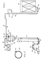
- FIG. 3 illustrates a vacuum drainage system capable of handling two different types of waste fluid flows, in accordance with additional aspects of the present invention.
- FIG. 1 A vacuum drainage system 10 incorporating a waste fluid discharge column 12 in accordance with the present invention is illustrated in FIG. 1.
- the vacuum drainage system 10 is illustrated in FIG. 1 as collecting waste fluid from a refrigerated case 16 located inside a supermarket. It will be understood, however, that the discharge column 12 described herein is not limited to a particular environment of use or application, but instead may be used in any type of vacuum drainage system which would benefit from the advantages disclosed herein.
- the vacuum drainage system 10 includes a main pipe 18 for transporting waste fluid to the discharge column 12.
- a collection branch 20 is connected to the main pipe 18.
- the collection branch 20 has an upstream end defining an intake opening 22 positioned below a waste fluid source, such as the refrigerated case 16.
- a collection area, such as a buffer box 24, is located downstream of the intake opening 22.
- the buffer box 24 is positioned so that waste fluid passing through the intake opening 22 flows toward the buffer box 24 under the force of gravity.
- a conduit 26 connects the buffer box 24 to the main pipe 18.
- a control valve 28 is disposed in the conduit 26 for selectively establishing fluid communication between the intake opening 22 and the main pipe 18.
- a vacuum source such as vacuum pump 30 is provided for generating negative pressure in the vacuum drainage system 10.
- the vacuum source 30 has an inlet 32 connected to a vacuum port 34 of the discharge column 12 by a conduit 36.
- the vacuum pump 30 is operable to evacuate air from the vacuum drainage system 10, thereby establishing a negative pressure level in the system.
- a lower section of the waste fluid discharge column 12 comprises a generally vertically oriented pipe 38 having a lower end 40 open to atmosphere and an upper end 42 closed off from atmosphere.
- a lower portion of the pipe 38 is formed with a U-shaped pipe section 44 having a relatively short downstream leg 45 for trapping a volume of waste fluid inside the pipe 38.
- a check valve 46 is attached to the U-shaped pipe section 44 for preventing back flow of waste fluid into the discharge column 12.
- the downstream leg 45 of the U-shaped pipe section 44 may be longer, thereby eliminating the need for a check valve.
- the U-shaped pipe section 44 may be omitted so that the check valve 46 is attached to the lower end of a straight pipe 38.
- an elbow 48 is attached to the check valve 46 for directing waste fluid into a desired collection point, such as a municipal sewer 50.
- the pipe 38 and associated fittings are preferably provided in 18,75 mm (3-4") diameters to take advantage of available standard fitting sizes and to minimize the cost of the fittings.
- the 18,75 mm (3-4") diameter pipe and fittings create a relatively small pipe volume, thereby reducing the required capacity of the vacuum source.
- an upper section of the waste fluid discharge column 12 comprises a chamber 51 having a cross-sectional area which is greater than a cross-sectional area of the pipe 38.
- the chamber 51 is attached to the upper end 42 of the pipe 38.
- the vacuum port 34 is formed in the chamber 51 so that the vacuum pump 30 fluidly communicates with the chamber 51.
- an inlet port 54 is formed in the chamber 51 for connection to the main pipe 18. Accordingly, it will be appreciated that operation of the vacuum pump 30 generates negative pressure in the chamber 51, vertical pipe 38, and main pipe 18.
- the chamber 51 is formed as a tank 52 (Fig.
- the chamber 51 is not limited to a specific component or a particular shape, but instead may be provided in a variety of different forms, as long as at least a portion of the chamber 51 has a larger cross-sectional area than the pipe 38. In fact, the chamber 51 may be formed integrally with the pipe 38 as an increased diameter portion of the pipe.
- the vacuum drainage system 10 is operable to transport waste fluid from the waste fluid source to the waste fluid discharge column 12. Waste fluid generated by the refrigerated case 16 is directed to the intake opening 22 of the associated collection branch 20, where the waste fluid flows under the force of gravity to the buffer box 24.
- the control valve 28 is normally in a closed position, but may be selectively actuated to an open position, thereby establishing fluid communication between the buffer box 24 and the main pipe 18. As a result, negative pressure is present at a downstream side of the buffer box 24 via the conduit 26 while atmospheric pressure is present at an upstream side of the buffer box 24 via the intake opening 22.
- the resulting pressure differential acts to push the fluid from the buffer box 24 and up the conduit 26 as a discrete volume or slug. The slug of fluid reaches the main pipe where it is either immediately transferred to the discharge column 12 or later transferred by subsequent control valve 28 operations.
- Waste fluid from the main pipe 18 enters the tank 52 through the inlet port 54. Any excess air pulled in with the fluid is exhausted by the vacuum pump 30 through the vacuum port 34 of the tank 52. The waste fluid flows through the tank 52 to collect in the vertical pipe 38.
- the negative pressure in the tank 52 and vertical pipe 38 creates a vacuum force which holds a specific volume of fluid in the vertical pipe 38. Accordingly, waste fluid will collect in the vertical pipe 38 to form a liquid column LC inside the vertical pipe.
- the height H of the liquid column LC depends primarily upon the negative pressure level generated by the vacuum pump 30 in the vertical pipe 38. For example, when the vacuum pump 30 creates a vacuum level of about 0,34 bar (10 inches Hg), the liquid column LC will have maximum height H of approximately 3,3 m (11 feet).
- the liquid column height is approximately 6,6 m (22 feet). Waste fluid will collect inside the vertical pipe 38 until the maximum height is reached. When additional waste fluid is added to the liquid column after it has reached the maximum height H, waste fluid is discharged from the lower end 40 of the pipe 38 until the liquid column lowers back to height H.
- the liquid column LC maintains a substantially constant height H, as described above. In certain situations, however, the liquid column LC may temporarily exceed the maximum height H. In high flow conditions, where a greater than normal amount of waste fluid is transported to the vertical pipe 38, the rate of fluid entering the pipe 38 may exceed the rate of fluid discharge out of the pipe 38. Under such conditions, the liquid column LC will temporarily exceed the normal maximum height H until the high flow ceases or slows and the excess fluid is discharged from the pipe 38. The liquid column height during high flow may reach the upper end 42 of the vertical pipe 38 and even enter the chamber 51, thereby creating a risk of flooding the vacuum source.
- the chamber 51 advantageously increases the fluid carrying capacity of the vertical pipe 38 near the upper end 42, thereby reducing the flood risk.
- an overflow protection device is preferably provided inside the chamber 51 for interrupting power to the vacuum source when the fluid inside the chamber reaches a certain level.
- the overflow protection device is a ball float 55 positioned at a particular height inside the tank 52.
- the ball float has a lead wire 56 operatively coupled to the vacuum source.
- the ball float moves in response to an increasing fluid level in the tank 52, thereby sending an overflow signal which interrupts power to the vacuum source.
- the illustrated embodiment shows a ball float, it will be appreciated that other overflow protection devices may be used, as long as they are capable of detecting a high fluid level in the tank and actuating in response to the high level to interrupt operation of the vacuum source.
- the discharge column 12 provides inexpensive and less complicated apparatus for discharging waste fluid into a desired collection point without requiring additional valves, controls and other auxiliary devices.
- the chamber 51 illustrated as the tank 52 in FIG. 1, creates an increased cross-sectional area in which the vacuum port 34 and inlet port 54 are formed. Accordingly, these ports may be spaced farther apart than in a vertical pipe having a uniform diameter, thereby more reliably separating the waste fluid from air.
- the pipe 38 advantageously has a smaller cross-sectional area to reduce cost and minimize the required vacuum source capacity.
- the inlet port 54 may be oriented so that waste fluid is introduced generally tangentially into the tank 52 to minimize the amount of any waste fluid being entrained in the incoming air (FIG. 2).
- the chamber 51 also increases the total volume of the system, thereby providing a vacuum buffer which helps to maintain the desired vacuum level in the system during operation.
- a vacuum drainage system 110 for handling three different types of waste fluids.
- the vacuum drainage system 110 comprises first, second, and third waste fluid discharge columns 112a, 112b, 112c.
- the vacuum drainage system 110 further includes first, second, and third main pipes 118a, 118b, 118c for transferring waste fluid into the respective discharge columns 112a, 112b, 112c.
- a collection branch 120a is attached to the main pipe 118a and has an intake opening 122a for receiving gray water, such as waste fluid from a meat preparation sink 114.
- the collection branch 120a further includes a buffer box 124a, a conduit 126a, and a control valve 128a similar to the system 10 described above.
- the collection branch 120b has an intake opening 122b, buffer box 124b, conduit 126b, and control valve 128b.
- the intake opening 122b of the collection branch 120b is positioned below a refrigerated case 116 and collects relatively clean condensate.
- the collection branch 120c transports black water from a toilet 115.
- the collection branch 120c has a conduit 126c connected to a control valve 128c which, in turn, is connected to an outlet of the toilet 115.
- a flush control unit 127 actuates the control valve 128c.
- the first, second, and third waste fluid discharge columns 112a, 112b, 112c each comprise a lower section having a vertically oriented pipe 138a, 138b, 138c.
- Each vertical pipe 138a, 138b, 138c has a lower end 140a, 140b, 140c open to atmosphere and an upper end 142a, 142b, 142c closed off from atmosphere.
- a lower portion of each pipe 138a, 138b, 138c is formed with a U-shaped pipe section 144a, 144b, 144c, and a check valve 146a, 146b, 146c is attached to each U-shaped pipe section 144a, 144b, 144c.
- each fluid discharge column 112a, 112b, 112c preferably includes a chamber 150a, 150b, 150c attached to the upper end 142a, 142b, 142c of the respective vertical pipes 138a, 138b, 138c.
- Each of the chambers 150a, 150b, 150c have a cross-sectional area which is larger than that of the respective pipe 138a, 138b, 138c.
- each chamber 150a, 150b, 150c is provided as a hollow tank 152a, 152b, 152c having a vacuum port 134a, 134b, 134c and an inlet port 154a, 154b, 154c.
- Inlet port 154a is attached to main pipe 118a
- inlet port 154b is attached to main pipe 118b
- inlet port 154c is attached to main pipe 118c.
- the vacuum ports 134a, 134b, 134c are attached by a common conduit 136 to a vacuum source, such as vacuum pump 130.
- the vacuum pump 130 operates to create a negative pressure in the tanks 152a, 152b, 152c, waste fluid discharge columns 112a, 112b, 112c, and main pipes 118a, 118b, 118c.
- the vacuum drainage system 110 operates in a similar manner as the vacuum drainage system 10 of the first embodiment described above.
- the intake opening 122a of the collection branch 120a receives a first waste fluid from the meat preparation sink 114.
- the first waste fluid passes through the intake opening 122a to collect in the buffer box 124a.
- the control valve 128a is temporarily opened to create a pressure differential across the fluid collected in the buffer box 124a, thereby transporting the fluid through the conduit 126a as a discrete volume.
- the waste fluid is transported through the main pipe 118a to the tank 152a, which subsequently empties into the vertical pipe 138a.
- the negative pressure level in the vertical pipe 138a holds a predetermined volume of fluid inside the pipe as a liquid column. Once the liquid column reaches its maximum height, additional fluid added to the top of the column causes an equal amount of fluid to discharge out of the lower end 140a of the pipe 138a.
- the collection branch 120b and waste fluid discharge column 112b operate in the same manner.
- the collection branch 120b collects a second waste fluid which is different from the first waste fluid.
- the second waste fluid comprises relatively clean condensate from the refrigerated case 116.
- the collection branch 120c which collects black water from the toilet 115, operates in a slightly different manner, while the waste fluid discharge column 112c operates as described above.
- the flush control unit 127 is responsive to a flush command to open the control valve 128c. When the control valve 128c is open, atmospheric pressure present inside the bowl of the toilet 115 pushes the third waste fluid through the conduit 126c and into the waste fluid discharge column 112c
- each discharge column may have one or more associated collection branch, in accordance with the present invention.
- each collection branch 120a, 120b, 120c is shown receiving waste fluid from a single source, it will be appreciated that each collection branch may serve two or more waste fluid sources as needed for a particular application.
- Fluid treatment apparatus 156 may be provided for treating waste fluid prior to discharge into a collection point, such as a community sewer 158.
- a collection point such as a community sewer 158.
- the first waste fluid generated by the meat preparation sink 114 and collected in the discharge column 112a is discharged from the lower end 140a of the vertical pipe 138a into an inlet of the fluid treatment apparatus 156, such as a grease trap.
- the grease trap removes grease from the first waste fluid so that it is suitable for discharge into the municipal sewer 158. Because the first fluid is handled separately, only the fluid requiring treatment is directed through the treatment apparatus.
- the second waste fluid described herein as condensate, is relatively clean and therefore does not require treatment. Accordingly, as shown in FIG. 3, the second waste fluid is discharged directly from the waste fluid discharge column 112b into the sewer 158. In the alternative, the second waste fluid may be reused on site, such as by providing a supply of toilet water.
- the third waste fluid is also discharged directly into the sewer 158.
- the system 110 handles this fluid stream separately, since local code may restrict the location of piping used to transport black water.
- the present invention brings to the art a new and improved waste fluid discharge column for use in a vacuum drainage system.
- the discharge column comprises a lower section having vertical pipe and an upper section having a chamber.
- the chamber allows for better separation of waste fluid and air, and provides a vacuum buffer for the drainage system.
- two or more waste fluid discharge columns may be connected to a single vacuum source to provide for separate handling of different types of waste fluids. While certain types of waste fluid may be directly discharged into a sewer, other types of waste fluid must first be treated, while still other types of waste fluid are more stringently governed by local code.
- the discharge column of the present invention provides inexpensive and reliable apparatus for discharging waste fluid from a vacuum drainage system.
Landscapes
- Health & Medical Sciences (AREA)
- Life Sciences & Earth Sciences (AREA)
- Engineering & Computer Science (AREA)
- Hydrology & Water Resources (AREA)
- Public Health (AREA)
- Water Supply & Treatment (AREA)
- Sewage (AREA)
- Physical Water Treatments (AREA)
- Jet Pumps And Other Pumps (AREA)
Applications Claiming Priority (2)
| Application Number | Priority Date | Filing Date | Title |
|---|---|---|---|
| US500406 | 2000-02-08 | ||
| US09/500,406 US6283140B1 (en) | 2000-02-08 | 2000-02-08 | Waste fluid discharge column |
Publications (2)
| Publication Number | Publication Date |
|---|---|
| EP1130180A2 true EP1130180A2 (de) | 2001-09-05 |
| EP1130180A3 EP1130180A3 (de) | 2003-06-18 |
Family
ID=23989270
Family Applications (1)
| Application Number | Title | Priority Date | Filing Date |
|---|---|---|---|
| EP20010101360 Withdrawn EP1130180A3 (de) | 2000-02-08 | 2001-01-22 | Vertikales Abwasserableitungsrohr |
Country Status (4)
| Country | Link |
|---|---|
| US (1) | US6283140B1 (de) |
| EP (1) | EP1130180A3 (de) |
| HU (1) | HUP0100354A2 (de) |
| PL (1) | PL345446A1 (de) |
Cited By (2)
| Publication number | Priority date | Publication date | Assignee | Title |
|---|---|---|---|---|
| EP1813734A1 (de) * | 2006-01-30 | 2007-08-01 | Evac International Oy | Vakuumabwassersystem |
| EP4414637A1 (de) * | 2023-02-09 | 2024-08-14 | Aquasolutions AG | Anlage zum abführen von abwasser insbesondere durch vakuumabsaugung |
Families Citing this family (3)
| Publication number | Priority date | Publication date | Assignee | Title |
|---|---|---|---|---|
| CA2724528C (en) | 2008-07-03 | 2017-03-28 | Adc Telecommunications, Inc. | Telecommunications wire having a channeled dielectric insulator and methods for manufacturing the same |
| US8292990B2 (en) * | 2008-09-05 | 2012-10-23 | Tsi, Incorporated | Nebulizer waste pressure reducer for HPLC systems |
| CN115823034B (zh) * | 2022-11-15 | 2026-02-13 | 河南赛诺特生物技术有限公司 | 一种孵育仓排液装置和免疫组化装置 |
Citations (1)
| Publication number | Priority date | Publication date | Assignee | Title |
|---|---|---|---|---|
| US4246925A (en) | 1977-12-14 | 1981-01-27 | Aktiebolaget Electrolux | Waste water vacuum conveyance method and apparatus |
Family Cites Families (5)
| Publication number | Priority date | Publication date | Assignee | Title |
|---|---|---|---|---|
| SE328531C (sv) * | 1969-02-14 | 1973-07-23 | Gustavsbergs Fabriker Ab | Avloppssystem |
| US3956776A (en) * | 1975-05-28 | 1976-05-18 | Thetford Corporation | Liquid waste material conveying system for toilets and the like |
| US4339232A (en) * | 1980-10-06 | 1982-07-13 | Campbell George T R | Pressure differential liquid transfer system |
| DE4436003C2 (de) * | 1994-10-08 | 2002-04-11 | F & F Filter Und Foerdertechni | Vorrichtung zum Entsorgen von flüssigen Medien |
| DE19753085A1 (de) * | 1997-11-29 | 1999-06-02 | F & F Filter Und Foerdertechni | Vorrichtung zum Entsorgen flüssiger Medien |
-
2000
- 2000-02-08 US US09/500,406 patent/US6283140B1/en not_active Expired - Fee Related
-
2001
- 2001-01-22 EP EP20010101360 patent/EP1130180A3/de not_active Withdrawn
- 2001-01-24 HU HU0100354A patent/HUP0100354A2/hu unknown
- 2001-01-26 PL PL34544601A patent/PL345446A1/xx unknown
Patent Citations (1)
| Publication number | Priority date | Publication date | Assignee | Title |
|---|---|---|---|---|
| US4246925A (en) | 1977-12-14 | 1981-01-27 | Aktiebolaget Electrolux | Waste water vacuum conveyance method and apparatus |
Cited By (4)
| Publication number | Priority date | Publication date | Assignee | Title |
|---|---|---|---|---|
| EP1813734A1 (de) * | 2006-01-30 | 2007-08-01 | Evac International Oy | Vakuumabwassersystem |
| KR101343638B1 (ko) | 2006-01-30 | 2013-12-20 | 에박 인터내셔널 오이 | 진공하수 시스템 |
| NO340675B1 (no) * | 2006-01-30 | 2017-05-29 | Evac Oy | Kloakksystem med vacuum. |
| EP4414637A1 (de) * | 2023-02-09 | 2024-08-14 | Aquasolutions AG | Anlage zum abführen von abwasser insbesondere durch vakuumabsaugung |
Also Published As
| Publication number | Publication date |
|---|---|
| US6283140B1 (en) | 2001-09-04 |
| HU0100354D0 (en) | 2001-03-28 |
| HUP0100354A2 (hu) | 2001-09-28 |
| PL345446A1 (en) | 2001-08-13 |
| EP1130180A3 (de) | 2003-06-18 |
Similar Documents
| Publication | Publication Date | Title |
|---|---|---|
| JP2808088B2 (ja) | 電気的給気制御装置を備えた高揚程能力の真空下水道装置 | |
| KR101479791B1 (ko) | 진공 하수 시스템 | |
| CN1163655C (zh) | 真空排水系统 | |
| FI110444B (fi) | Alipaineviemärijärjestelmä | |
| SE504962C2 (sv) | Anordning vid ett avloppssystem i en byggnad för olika grader av förorenat avloppsvatten | |
| US6131596A (en) | Automatic vacuum isolation valve network for a vacuum collection system | |
| EP1130180A2 (de) | Vertikales Abwasserableitungsrohr | |
| IL111666A (en) | Cleaning system for cleaning the face of liquid conductor pipes and an ancillary device | |
| US5022114A (en) | Device for suctioning up and removing a contaminated liquid | |
| KR20000011409A (ko) | 하수시스템 | |
| EP0415360A2 (de) | Vakuumabwassersammelvorrichtung | |
| US6990993B2 (en) | Vacuum drainage system | |
| EP0544261B1 (de) | Zwischenphase-Vakuumventil | |
| JP2684526B2 (ja) | 真空式汚水集排水装置と真空式下水道 | |
| US4108192A (en) | Method for sewage removal from multi-household connections | |
| FI77911B (fi) | Foerfarande foer stoetvis transport av vaetska. | |
| JP2001081852A (ja) | 真空式下水道システム | |
| WO1992014889A1 (fr) | Siphon inverse pour systeme d'egouts du type a aspiration | |
| EP0530203B1 (de) | Verbesserung bei einem abwassersystem | |
| EP1896668B1 (de) | Verfahren und system zum entladen eines abfallstroms aus einer toilette und siphon-installation zur verwendung damit | |
| JPH1143982A (ja) | 真空下水管の空気取入れ装置 | |
| JP2639261B2 (ja) | 真空式下水道の伏越 | |
| HK1034758B (en) | Vacuum drainage system | |
| EP1115952A1 (de) | Abwassersystem und methode zur abwasserbehandlung | |
| JPH06229001A (ja) | 真空式下水道の真空下水管路 |
Legal Events
| Date | Code | Title | Description |
|---|---|---|---|
| PUAI | Public reference made under article 153(3) epc to a published international application that has entered the european phase |
Free format text: ORIGINAL CODE: 0009012 |
|
| AK | Designated contracting states |
Kind code of ref document: A2 Designated state(s): AT BE CH CY DE DK ES FI FR GB GR IE IT LI LU MC NL PT SE TR |
|
| AX | Request for extension of the european patent |
Free format text: AL;LT;LV;MK;RO;SI |
|
| PUAL | Search report despatched |
Free format text: ORIGINAL CODE: 0009013 |
|
| AK | Designated contracting states |
Designated state(s): AT BE CH CY DE DK ES FI FR GB GR IE IT LI LU MC NL PT SE TR |
|
| AX | Request for extension of the european patent |
Extension state: AL LT LV MK RO SI |
|
| 17P | Request for examination filed |
Effective date: 20031127 |
|
| AKX | Designation fees paid |
Designated state(s): AT BE CH CY DE DK ES FI FR GB GR IE IT LI LU MC NL PT SE TR |
|
| STAA | Information on the status of an ep patent application or granted ep patent |
Free format text: STATUS: THE APPLICATION HAS BEEN WITHDRAWN |
|
| 18W | Application withdrawn |
Effective date: 20050603 |