EP1130281A2 - Ausgleichswelle für Verbrennungsmotoren - Google Patents
Ausgleichswelle für Verbrennungsmotoren Download PDFInfo
- Publication number
- EP1130281A2 EP1130281A2 EP00126266A EP00126266A EP1130281A2 EP 1130281 A2 EP1130281 A2 EP 1130281A2 EP 00126266 A EP00126266 A EP 00126266A EP 00126266 A EP00126266 A EP 00126266A EP 1130281 A2 EP1130281 A2 EP 1130281A2
- Authority
- EP
- European Patent Office
- Prior art keywords
- balance shaft
- cam
- drive
- shaft
- crankshaft
- Prior art date
- Legal status (The legal status is an assumption and is not a legal conclusion. Google has not performed a legal analysis and makes no representation as to the accuracy of the status listed.)
- Withdrawn
Links
Images
Classifications
-
- F—MECHANICAL ENGINEERING; LIGHTING; HEATING; WEAPONS; BLASTING
- F16—ENGINEERING ELEMENTS AND UNITS; GENERAL MEASURES FOR PRODUCING AND MAINTAINING EFFECTIVE FUNCTIONING OF MACHINES OR INSTALLATIONS; THERMAL INSULATION IN GENERAL
- F16F—SPRINGS; SHOCK-ABSORBERS; MEANS FOR DAMPING VIBRATION
- F16F15/00—Suppression of vibrations in systems; Means or arrangements for avoiding or reducing out-of-balance forces, e.g. due to motion
- F16F15/22—Compensation of inertia forces
- F16F15/26—Compensation of inertia forces of crankshaft systems using solid masses, other than the ordinary pistons, moving with the system, i.e. masses connected through a kinematic mechanism or gear system
- F16F15/261—Compensation of inertia forces of crankshaft systems using solid masses, other than the ordinary pistons, moving with the system, i.e. masses connected through a kinematic mechanism or gear system where masses move linearly
-
- F—MECHANICAL ENGINEERING; LIGHTING; HEATING; WEAPONS; BLASTING
- F02—COMBUSTION ENGINES; HOT-GAS OR COMBUSTION-PRODUCT ENGINE PLANTS
- F02B—INTERNAL-COMBUSTION PISTON ENGINES; COMBUSTION ENGINES IN GENERAL
- F02B67/00—Engines characterised by the arrangement of auxiliary apparatus not being otherwise provided for, e.g. the apparatus having different functions; Driving auxiliary apparatus from engines, not otherwise provided for
- F02B67/04—Engines characterised by the arrangement of auxiliary apparatus not being otherwise provided for, e.g. the apparatus having different functions; Driving auxiliary apparatus from engines, not otherwise provided for of mechanically-driven auxiliary apparatus
- F02B67/06—Engines characterised by the arrangement of auxiliary apparatus not being otherwise provided for, e.g. the apparatus having different functions; Driving auxiliary apparatus from engines, not otherwise provided for of mechanically-driven auxiliary apparatus driven by means of chains, belts, or like endless members
-
- F—MECHANICAL ENGINEERING; LIGHTING; HEATING; WEAPONS; BLASTING
- F02—COMBUSTION ENGINES; HOT-GAS OR COMBUSTION-PRODUCT ENGINE PLANTS
- F02B—INTERNAL-COMBUSTION PISTON ENGINES; COMBUSTION ENGINES IN GENERAL
- F02B75/00—Other engines
- F02B75/16—Engines characterised by number of cylinders, e.g. single-cylinder engines
- F02B75/18—Multi-cylinder engines
- F02B75/22—Multi-cylinder engines with cylinders in V, fan, or star arrangement
-
- F—MECHANICAL ENGINEERING; LIGHTING; HEATING; WEAPONS; BLASTING
- F16—ENGINEERING ELEMENTS AND UNITS; GENERAL MEASURES FOR PRODUCING AND MAINTAINING EFFECTIVE FUNCTIONING OF MACHINES OR INSTALLATIONS; THERMAL INSULATION IN GENERAL
- F16F—SPRINGS; SHOCK-ABSORBERS; MEANS FOR DAMPING VIBRATION
- F16F15/00—Suppression of vibrations in systems; Means or arrangements for avoiding or reducing out-of-balance forces, e.g. due to motion
- F16F15/22—Compensation of inertia forces
- F16F15/26—Compensation of inertia forces of crankshaft systems using solid masses, other than the ordinary pistons, moving with the system, i.e. masses connected through a kinematic mechanism or gear system
- F16F15/264—Rotating balancer shafts
Definitions
- the invention relates to balancer shafts for internal combustion engines, which simultaneously form the drive of auxiliary units according to the preamble of the main claim.
- balancing shafts are used to compensate for free mass forces and / or moments, which have rotating balancing masses and are driven in a fixed transmission ratio to the crankshaft.
- the first balancer shaft driven by the crankshaft via gear wheels drives a lubricating oil pump, the second wheel of which drives a second balancer shaft and serves as a reversing drive.
- the gear pump as an ancillary unit has only centrically rotating parts and is driven with quasi-continuous torque at lower revs.
- crankshaft outgoing gear drive for two arranged below the crankshaft Balance shafts, the gear drive using a large Intermediate wheel drives a gear oil pump as an auxiliary unit
- the mass of the Drive does not act as an eccentric rotating mass.
- auxiliary units are Piston delivery units for fuel or lubricating oil shown - Fig.3 -.
- the of the Compensating mass driven parts of the ancillaries can with this Contribute to mass balance.
- the object of the invention is to use the rotating masses of a balance shaft when driving an auxiliary unit with a preferably strongly pulsating drive torque, preferably an injection pump or a pressure generator for injection systems for internal combustion engines.
- a preferably strongly pulsating drive torque preferably an injection pump or a pressure generator for injection systems for internal combustion engines.
- the moving masses of the drive and possibly the auxiliary unit should be used to balance the free mass forces and / or moments.
- the drive cam of the auxiliary unit is advantageous on the existing balance shaft arranged. It is therefore used to drive the Ancillary units do not require any additional installation space, making them compact Arrangement of engine, balancer shaft and auxiliary unit created and the total component effort required reduced.
- the cam forms part of the the balancing mass arranged on the shaft.
- the mass of the counterweights can thus be reduced and the energy of the orbiting masses is used Drive of the auxiliary unit used.
- the cam provides a Pump, preferably a piston pump, driven for an injection system.
- a Pump preferably a piston pump
- the inventive design of the drive by means of the balancer shaft Arranged cam is advantageous because of the changing Torque peaks occur due to the inertia of the circulating masses are damped.
- a balancer shaft 1 according to the invention can be driven by the crankshaft in two- and four-stroke engines, rotate synchronously with crankshaft speed or double crankshaft speed.
- a sliding shaft 1 which rotates at the crankshaft speed in the opposite direction of the crankshaft direction of rotation, can be used for mass and torque compensation of the first order of the crank mechanism.
- Balance shafts 1 rotating at double crankshaft speed can balance mass forces and moments of the second order and also have cams for driving one or more delivery elements of a pump for injection systems.
- the rotating masses of the compensating arrangement reduce high torque fluctuations, which disadvantageously occur in the drive between the crankshaft and the drive shaft, typically in high-pressure injection systems with conveyor elements.
- the combination according to the invention of a shaft, which is both balancer and camshaft has the aforementioned dynamic advantage for its drive and allows the saving of special flywheels on the drive shaft of the injection conveyor elements or pump of an injection system and their weight.
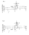
- the balance shaft 1 shows a balance shaft 1 designed according to the invention for internal combustion engines with balance weights 2 arranged eccentrically to their axis of rotation (DAAW); 8.
- the balance shaft 1 is rotatable in 3 fixed bearings 3; 4; 5 out and is driven by a form-fitting drive means - not shown - which engages, for example, a chain sprocket in a drive element 6 arranged in a rotationally fixed manner on the balance shaft 1.
- On the balance shaft 1 at least one cam 7 is rotatably arranged with the z. B. a role 9 of one or more actuating devices 10 of auxiliary units, preferably one or more delivery elements of a high-pressure pump for common rail injection systems or in two-stroke engines of pump nozzle elements, directly or indirectly engaged, not shown.
- the roller 9, which is rotatably mounted on the actuating device 10, is in constant engagement with the cam 7 by means of the force of a spring 11, which is firmly supported on its side facing away from the balancer shaft 1 (not shown
- FIG. 2 shows a balancer shaft 13 designed according to the invention for Internal combustion engines shown. This is part of an arrangement to compensate for Mass forces and / or 2nd order moments, preferably for a 4-cylinder 4-stroke Engine.
- Another balancer shaft - not shown - is arranged axially parallel to it. Both balance shafts run in opposite synchronous with double Crankshaft speed around and can be at the same level to generate a periodically rotating mass force or offset in its amount to generate an additional alternating torque.
- Analogous to that in FIG. 1 arrangement shown is the balance shaft in three fixed bearings 3; 4 and 5 rotatably mounted and is driven by the drive element 6 in a fixed ratio of 2: 1 for 4-stroke engines driven by the crankshaft.
- a cam 7 for driving one Auxiliary unit is rotatably arranged on the balance shaft 13 and forms part of the total mass balance. The operation of at least one Auxiliary units are carried out analogously as described in FIG. 1.
Landscapes
- Engineering & Computer Science (AREA)
- General Engineering & Computer Science (AREA)
- Mechanical Engineering (AREA)
- Chemical & Material Sciences (AREA)
- Combustion & Propulsion (AREA)
- Physics & Mathematics (AREA)
- Acoustics & Sound (AREA)
- Aviation & Aerospace Engineering (AREA)
- Shafts, Cranks, Connecting Bars, And Related Bearings (AREA)
- Valve-Gear Or Valve Arrangements (AREA)
Abstract
Description
Allgemein vorbekannt sind, z. B. durch die Schriften US 4 703 724 und US 5 535 643 gattungsgemäße Ausgleichswellen für Verbrennungsmotoren, von denen eine gleichzeitig einen Antrieb eines Nebenaggregates bildet. Die von der Kurbelwelle über Zahnräder angetriebene erste Ausgleichswelle treibt eine Schmierölpumpe an, deren zweites Rad eine zweite Ausgleichswelle treibt und dabei als Umkehrtrieb dient. Die Zahnradpumpe als Nebenaggregat weist nur zentrisch umlaufende Teile auf und wird bei ieder Umdrehung mit quasi kontinuierlichem Drehmoment angetrieben.
Vorbekannte Anordnungen zum Massenausgleich sind mit zwei in unterschiedlicher Distanz beidseitig der Kurbelwelle, in axialer Richtung parallel zu dieser, angeordneten Ausgleichswellen ausgestattet. Der Antrieb einer der Ausgleichswellen - DE 32 11 655 A1 - oder auch beider - DE 25 08 325 A1 - wird zum Antrieb von Nebenaggregaten genutzt.
Bei der Lösung gemäß der Schrift DE 32 11 655 A1 wird die näher an der Kurbelwelle liegende erste Ausgleichswelle von der Kurbelwelle direkt über ein Zahnradpaar angetrieben. Der Antrieb der zweiten Ausgleichswelle erfolgt über einen Kettentrieb, welcher über ein gesondertes Zahnrad läuft, welches die Schmierölpumpe mit niedrigerer Drehzahl als die Kurbelwelle antreibt.
Dabei sollen die bewegten Massen des Antriebes und ggf. des Nebenaggregates für den Ausgleich der freien Massenkräfte und / oder -momente genutzt werden.
Bei beiden Motorenarten kann eine Ausgleienswelle 1, die mit Kurbelwellendrehzahl jedoch entgegengesetzt der Kurbelwellen-Drehrichtung umläuft, zum Massen- und Momenten-Ausgleich 1. Ordnung des Kurbeltriebes genutzt werden. Mit doppelter Kurbelwellendrehzahl umlaufende Ausgleichswellen 1 können Massenkräfte und Momente 2. Ordnung ausgleichen und gleichfalls Nocken zum Antrieb von einem oder mehreren Förderelementen einer Pumpe für Einspritzanlagen aufweisen.
Bei allen Anwendungen vermindern die umlaufenden Massen der Ausgleichsanordnung hohe Drehmoment-Schwankungen, die im Antrieb zwischen Kurbelwelle und der Antriebswelle in nachteiliger Weise typisch bei Hochdruck-Einspritzanlagen mit Förderelementen auftreten.
Die erfindungsgemäße Kombination einer Welle, die sowohl Ausgleichs- als auch Nockenwelle ist, weist den vorerwähnten dynamischen Vorteil für ihre Antrieb auf und erlaubt die Einsparung von speziellen Schwungmassen auf der Antriebswelle der Einspritzförderelemente bzw. Pumpe einer Einspritzanlage sowie deren Gewicht.
Auf der Ausgleichswelle 1 ist mindestens ein Nocken 7 drehfest angeordnet, mit dem z. B. eine Rolle 9 einer oder mehrerer Betätigungseinrichtungen 10 von Nebenaggregaten, vorzugsweise von einem oder mehreren Förderelementen einer Hochdruckpumpe für Common-rail-Einspritzanlagen oder bei Zweitaktmotoren von Pumpedüse-Elementen, direkt oder indirekt im Eingriff stehen, -nicht dargestellt-. Die drehbar an der Betätigungseinrichtung 10 gelagerte Rolle 9 steht mittels der Kraft einer Feder 11, die auf ihrer der Ausgleichswelle 1 abgewandten Seite fest - nicht dargestellt- abgestützt ist, mit dem Nocken 7 stetig im Eingriff.
Claims (5)
- Ausgleichswellen für Verbrennungsmotoren, die zum Ausgleich freier Massenkräfte und / oder -momente umlaufenden Ausgleichsmassen (2,8) aufweisen, in einem festen Übersetzungsverhältnis zur Kurbelwelle angetrieben sind und gleichzeitig den Antrieb von Nebenaggregaten bilden,
dadurch gekennzeichnet,
daß auf der Ausgleichswelle (1) mindestens ein Nocken (7) zum Antrieb eines Nebenaggregates drehfest angeordnet ist. - Ausgleichswelle (1) nach Anspruch 1,
dadurch gekennzeichnet,
daß der Nocken (7) einen Teil der auf ihr angeordneten Ausgleichsmasse bildet. - Ausgleichswelle (1) nach Anspruch 1,
dadurch gekennzeichnet,
daß die auf ihr angeordneten Ausgleichsmassen (2, 8) so gestaltet sind, daß Ausgleichsmassen (2), Nocken (7) und die jeweils zugeordnete Betätigungseinrichtung (10) des Nebenaggregates die Gesamtausgleichsmasse bilden. - Ausgleichswelle (1) nach Anspruch 1,
dadurch gekennzeichnet,
daß die umlaufenden Nocken (7) jeweils mit einem oder mehreren Einspritzelementen direkt oder indirekt im Eingriff stehen. - Ausgleichswelle nach Anspruch 1 und /oder 4,
dadurch gekennzeichnet,
daß die Ausgleichwelle und das von ihr mittels eines Nockens angetriebene Nebenaggregat bei Verbrennungsmotoren mit V-förmig stehenden Zylinderreihen im Freiraum zwischen den Zylindern angeordnet ist.
Applications Claiming Priority (2)
| Application Number | Priority Date | Filing Date | Title |
|---|---|---|---|
| DE1999128416 DE19928416A1 (de) | 1999-12-15 | 1999-12-15 | Ausgleichswelle für Verbrennungsmotoren |
| DE19928416 | 1999-12-15 |
Publications (2)
| Publication Number | Publication Date |
|---|---|
| EP1130281A2 true EP1130281A2 (de) | 2001-09-05 |
| EP1130281A3 EP1130281A3 (de) | 2001-09-12 |
Family
ID=7912048
Family Applications (1)
| Application Number | Title | Priority Date | Filing Date |
|---|---|---|---|
| EP00126266A Withdrawn EP1130281A3 (de) | 1999-12-15 | 2000-12-01 | Ausgleichswelle für Verbrennungsmotoren |
Country Status (2)
| Country | Link |
|---|---|
| EP (1) | EP1130281A3 (de) |
| DE (1) | DE19928416A1 (de) |
Cited By (4)
| Publication number | Priority date | Publication date | Assignee | Title |
|---|---|---|---|---|
| EP1626200A1 (de) * | 2004-08-09 | 2006-02-15 | Mazda Motor Corporation | Motorschwingungssystem |
| FR3027989A1 (fr) * | 2014-10-30 | 2016-05-06 | Skf Ab | Arbre d'equilibrage et moteur a combustion interne |
| FR3031784A1 (fr) * | 2015-01-20 | 2016-07-22 | Skf Ab | Arbre d'equilibrage et moteur a combustion interne |
| FR3031783A1 (fr) * | 2015-01-20 | 2016-07-22 | Skf Ab | Dispositif comprenant un arbre, au moins trois roulements et une structure destinee a supporter une charge radiale |
Families Citing this family (7)
| Publication number | Priority date | Publication date | Assignee | Title |
|---|---|---|---|---|
| SE526393C2 (sv) * | 2003-11-04 | 2005-09-06 | Scania Cv Abp | Arrangemang och förfarande för att balansera en förbränningsmotor i ett fordon |
| WO2008120226A1 (en) * | 2007-03-29 | 2008-10-09 | Tata Motors Limited | An integrated shaft for twin cylinder internal combustion inline common rail diesel engine |
| DE102007057095A1 (de) | 2007-11-20 | 2009-06-04 | Hs Genion Gmbh | Besonders funktionssicherer und feinstufiger Verstellbeschlag |
| DE102008005325A1 (de) * | 2008-01-21 | 2009-07-30 | Audi Ag | Gleichteileanordnung bei Brennkraftmaschinen für einen Umschlingungstrieb |
| CN101655138B (zh) * | 2009-09-29 | 2012-12-12 | 昆明云内动力股份有限公司 | 一种三缸柴油机的平衡轴 |
| JP2013181567A (ja) * | 2012-02-29 | 2013-09-12 | Honda Motor Co Ltd | バランサ軸 |
| EP4726210A1 (de) * | 2024-10-08 | 2026-04-15 | Koenigsegg Automotive AB | Ausgleich einer kompressor-motor-baugruppe |
Citations (6)
| Publication number | Priority date | Publication date | Assignee | Title |
|---|---|---|---|---|
| DE1773275U (de) | 1957-03-04 | 1958-08-28 | Werner Spannagel | Feineinstell-kugellagergehaeuse fuer jede beliebige form und anwendung. |
| DE2508325A1 (de) | 1974-07-24 | 1976-02-12 | Mitsubishi Motors Corp | Anordnung zum bewegen einer ausgleichseinrichtung eines motors |
| DE3211655A1 (de) | 1982-03-30 | 1983-10-13 | Ford-Werke AG, 5000 Köln | Brennkraftmaschine mit einem massenausgleich zweiter ordnung |
| DE3607133A1 (de) | 1986-03-05 | 1987-09-10 | Kloeckner Humboldt Deutz Ag | Einrichtung zum ausgleich von massenkraeften und massenmomenten |
| US4703724A (en) | 1986-05-29 | 1987-11-03 | Chrysler Motors Corporation | Engine balancing device with a lubricant side discharge |
| US5535643A (en) | 1993-11-12 | 1996-07-16 | General Motors Corporation | Anti-rattle engine balancer which drives associated oil pump |
Family Cites Families (8)
| Publication number | Priority date | Publication date | Assignee | Title |
|---|---|---|---|---|
| US3110195A (en) * | 1961-12-27 | 1963-11-12 | Gen Motors Corp | Countershaft driving system for internal combustion engine and the like |
| AT378585B (de) * | 1984-01-16 | 1985-08-26 | Avl Verbrennungskraft Messtech | Brennkraftmaschine mit massenausgleich i. ordnung |
| DE4030568A1 (de) * | 1990-09-27 | 1992-04-09 | Bayerische Motoren Werke Ag | Mit einem steuernocken versehene steuerwelle zur periodischen betaetigung von maschineneinrichtungen, insbesondere gaswechselventile in brennkraftmaschinen |
| DE4117876C1 (en) * | 1991-05-31 | 1992-08-13 | Bayerische Motoren Werke Ag, 8000 Muenchen, De | Hollow IC engine camshaft with equalising mass - has extra weight of fluidic material in cavity widening bounded by eccentric peripheral sectionc |
| FR2695682B1 (fr) * | 1992-09-11 | 1994-10-21 | Inst Francais Du Petrole | Moteur à deux temps à injection pneumatique et à équilibrage du premier ordre des masses alternatives. |
| GB9601323D0 (en) * | 1996-01-23 | 1996-03-27 | Decorule Ltd | Reciprocatory machine |
| JP3307233B2 (ja) * | 1996-07-24 | 2002-07-24 | スズキ株式会社 | 船外機のエンジン |
| JP3862345B2 (ja) * | 1997-01-31 | 2006-12-27 | 本田技研工業株式会社 | 2サイクルエンジンのポンプ駆動構造 |
-
1999
- 1999-12-15 DE DE1999128416 patent/DE19928416A1/de not_active Ceased
-
2000
- 2000-12-01 EP EP00126266A patent/EP1130281A3/de not_active Withdrawn
Patent Citations (6)
| Publication number | Priority date | Publication date | Assignee | Title |
|---|---|---|---|---|
| DE1773275U (de) | 1957-03-04 | 1958-08-28 | Werner Spannagel | Feineinstell-kugellagergehaeuse fuer jede beliebige form und anwendung. |
| DE2508325A1 (de) | 1974-07-24 | 1976-02-12 | Mitsubishi Motors Corp | Anordnung zum bewegen einer ausgleichseinrichtung eines motors |
| DE3211655A1 (de) | 1982-03-30 | 1983-10-13 | Ford-Werke AG, 5000 Köln | Brennkraftmaschine mit einem massenausgleich zweiter ordnung |
| DE3607133A1 (de) | 1986-03-05 | 1987-09-10 | Kloeckner Humboldt Deutz Ag | Einrichtung zum ausgleich von massenkraeften und massenmomenten |
| US4703724A (en) | 1986-05-29 | 1987-11-03 | Chrysler Motors Corporation | Engine balancing device with a lubricant side discharge |
| US5535643A (en) | 1993-11-12 | 1996-07-16 | General Motors Corporation | Anti-rattle engine balancer which drives associated oil pump |
Cited By (4)
| Publication number | Priority date | Publication date | Assignee | Title |
|---|---|---|---|---|
| EP1626200A1 (de) * | 2004-08-09 | 2006-02-15 | Mazda Motor Corporation | Motorschwingungssystem |
| FR3027989A1 (fr) * | 2014-10-30 | 2016-05-06 | Skf Ab | Arbre d'equilibrage et moteur a combustion interne |
| FR3031784A1 (fr) * | 2015-01-20 | 2016-07-22 | Skf Ab | Arbre d'equilibrage et moteur a combustion interne |
| FR3031783A1 (fr) * | 2015-01-20 | 2016-07-22 | Skf Ab | Dispositif comprenant un arbre, au moins trois roulements et une structure destinee a supporter une charge radiale |
Also Published As
| Publication number | Publication date |
|---|---|
| DE19928416A1 (de) | 2001-07-05 |
| EP1130281A3 (de) | 2001-09-12 |
Similar Documents
| Publication | Publication Date | Title |
|---|---|---|
| EP0462411B1 (de) | Momentenausgleich zweiter Ordnung an Fünfzylinder-Reihen-Brennkraftmaschinen | |
| DE102007025549B4 (de) | Verfahren und Vorrichtung zum Vermindern von Drehungleichförmigkeiten der Kurbelwelle einer Kolbenbrennkraftmaschine | |
| EP0599125B1 (de) | Antrieb einer Ausgleichswelle an einer V-Brennkraftmaschine | |
| DE2720284B2 (de) | Schubkurbelsystem-Baureihe | |
| EP1082548B1 (de) | Kupplungselement zur verbindung von zwei gleichachsig, hintereinander und mit querabstand zueinander angeordneten, achsparallelen wellen | |
| DE2822589C2 (de) | Vorrichtung zum Ausgleichen der freien Massenkräfte und -momente zweiter Ordnung an einer Hubkolben-Brennkraftmaschine | |
| DE2735384C2 (de) | Zweizylinder-Reihenmotor mit umlaufenden Massen zweier Ausgleichsvorrichtungen | |
| EP1130281A2 (de) | Ausgleichswelle für Verbrennungsmotoren | |
| DE10008425B4 (de) | Kupplungselement zur Verbindung von zwei gleichachsig hintereinander und mit Querabstand zueinander angeordneten achsparallelen Wellen, insbesondere zur Verwendung an einer Kolbenbrennkraftmaschine mit einstellbarer Verlagerung der Kurbelwelle | |
| DE69906971T2 (de) | Maschine mit doppeltem hub | |
| EP3207233B1 (de) | Stromaggregat | |
| DE3720559C2 (de) | Einrichtung zum Ausgleich von Wechselmomenten | |
| DE10245529A1 (de) | Motor mit Ausgleichsvorrichtung für ein Kippmoment zweiter Ordnung | |
| EP1114259A1 (de) | Massenausgleichssystem mit einer schmierölpumpe für hubkolbenmotoren | |
| DE2829042C2 (de) | Einrichtung zum Ausgleich der Massenkräfte von Hubkolben-Kurbelwellenmaschinen | |
| EP2539606A1 (de) | Massenausgleichsvorrichtung einer brennkraftmaschine | |
| DE102010014218A1 (de) | Drehkolbenpumpe und Verfahren zum Betreiben einer Drehkolbenpumpe | |
| DE3445430A1 (de) | Hubkolbenmaschine, insbesondere brennkraftmaschine | |
| DE102010055584A1 (de) | Vorrichtung zum Massenausgleich | |
| EP0700494B1 (de) | Schubkurbelgetriebe | |
| WO2000057073A1 (de) | Kupplungselement zur verbindung von zwei gleichachsig hintereinander und mit querabstand zueinander angeordneten achsparallelen wellen | |
| DE3840307A1 (de) | Einrichtung zum ausgleich von massenkraeften und wechselmomenten | |
| EP0121728A2 (de) | Zweizylinder-Viertakt-Brennkraftmaschine, insbesondere für Motorräder mit in Fahrtrichtung angeordneter Kurbelwelle | |
| DE19708819B4 (de) | Einrichtung zur kraftschlüssigen Eingriffssicherung für Zahntriebe von umlaufenden Ausgleichsmassen bei Verbrennungsmotoren | |
| DE19821170A1 (de) | Vorrichtung mit um die Kurbelwellenachse rotierenden Ausgleichsmassen für Kolbenmaschinen |
Legal Events
| Date | Code | Title | Description |
|---|---|---|---|
| PUAI | Public reference made under article 153(3) epc to a published international application that has entered the european phase |
Free format text: ORIGINAL CODE: 0009012 |
|
| PUAL | Search report despatched |
Free format text: ORIGINAL CODE: 0009013 |
|
| AK | Designated contracting states |
Kind code of ref document: A2 Designated state(s): AT BE CH CY DE DK ES FI FR GB GR IE IT LI LU MC NL PT SE TR Kind code of ref document: A2 Designated state(s): DE ES FR IT |
|
| AX | Request for extension of the european patent |
Free format text: AL;LT;LV;MK;RO;SI |
|
| AK | Designated contracting states |
Kind code of ref document: A3 Designated state(s): AT BE CH CY DE DK ES FI FR GB GR IE IT LI LU MC NL PT SE TR |
|
| AX | Request for extension of the european patent |
Free format text: AL;LT;LV;MK;RO;SI |
|
| AKX | Designation fees paid |
Free format text: DE ES FR IT |
|
| STAA | Information on the status of an ep patent application or granted ep patent |
Free format text: STATUS: THE APPLICATION IS DEEMED TO BE WITHDRAWN |
|
| 18D | Application deemed to be withdrawn |
Effective date: 20020313 |