EP1130338A2 - Appareil de chauffage avec boíte encastrée pour un échangeur de chaleur - Google Patents
Appareil de chauffage avec boíte encastrée pour un échangeur de chaleur Download PDFInfo
- Publication number
- EP1130338A2 EP1130338A2 EP01104997A EP01104997A EP1130338A2 EP 1130338 A2 EP1130338 A2 EP 1130338A2 EP 01104997 A EP01104997 A EP 01104997A EP 01104997 A EP01104997 A EP 01104997A EP 1130338 A2 EP1130338 A2 EP 1130338A2
- Authority
- EP
- European Patent Office
- Prior art keywords
- cover plate
- heating arrangement
- arrangement according
- rear wall
- side walls
- Prior art date
- Legal status (The legal status is an assumption and is not a legal conclusion. Google has not performed a legal analysis and makes no representation as to the accuracy of the status listed.)
- Granted
Links
- 238000009434 installation Methods 0.000 claims abstract description 82
- 238000010438 heat treatment Methods 0.000 claims abstract description 28
- 238000009423 ventilation Methods 0.000 claims abstract description 21
- 230000000694 effects Effects 0.000 claims description 6
- 230000007704 transition Effects 0.000 claims description 3
- 239000003570 air Substances 0.000 description 21
- 229910000831 Steel Inorganic materials 0.000 description 4
- 238000005253 cladding Methods 0.000 description 4
- 239000010959 steel Substances 0.000 description 4
- 229910052782 aluminium Inorganic materials 0.000 description 2
- XAGFODPZIPBFFR-UHFFFAOYSA-N aluminium Chemical compound [Al] XAGFODPZIPBFFR-UHFFFAOYSA-N 0.000 description 2
- 239000012080 ambient air Substances 0.000 description 2
- 238000001816 cooling Methods 0.000 description 2
- 238000002955 isolation Methods 0.000 description 2
- 238000004519 manufacturing process Methods 0.000 description 2
- 229910052751 metal Inorganic materials 0.000 description 2
- 239000002184 metal Substances 0.000 description 2
- 230000000630 rising effect Effects 0.000 description 2
- 241000283074 Equus asinus Species 0.000 description 1
- 241000446313 Lamella Species 0.000 description 1
- 238000009825 accumulation Methods 0.000 description 1
- 230000001419 dependent effect Effects 0.000 description 1
- 238000011161 development Methods 0.000 description 1
- 230000018109 developmental process Effects 0.000 description 1
- 238000007599 discharging Methods 0.000 description 1
- 238000005265 energy consumption Methods 0.000 description 1
- 230000003287 optical effect Effects 0.000 description 1
- 238000013021 overheating Methods 0.000 description 1
- 230000008092 positive effect Effects 0.000 description 1
- 230000005855 radiation Effects 0.000 description 1
Images



Classifications
-
- F—MECHANICAL ENGINEERING; LIGHTING; HEATING; WEAPONS; BLASTING
- F24—HEATING; RANGES; VENTILATING
- F24H—FLUID HEATERS, e.g. WATER OR AIR HEATERS, HAVING HEAT-GENERATING MEANS, e.g. HEAT PUMPS, IN GENERAL
- F24H9/00—Details
- F24H9/02—Casings; Cover lids; Ornamental panels
Definitions
- the invention relates to a heating arrangement according to the preamble of claim 1 with a built-in box for a heat exchanger.
- Heat exchangers are e.g. B. part of gas-powered heaters, which for Caravan heating can be used.
- the heaters essentially consisting of a burner and an exhaust gas heat exchanger not least built into a cabinet for optical reasons, so that the heat emitted from the heat exchanger to the ambient air predominantly via the front of the cabinet, e.g. B. must escape through a louvre grid. So that the cabinet that receives the heating does not overheat the heat exchanger is placed in a so-called installation box, the convection heat emitted by the heat exchanger into the living room directs and continues to reflect heat radiation in the caravan space.
- installation boxes have the task of covering the Fix heating and additional devices, such as. B. an additional electric heater or a fan for distributing a warm air flow in the caravan area, to wear.
- the installation box thus serves on the one hand as heat protection for the cabinet, on the other hand as an assembly and mounting box for the necessary Aggregates.
- FIG. 3 Such a known arrangement is shown in FIG. 3.
- the gas-powered caravan heater shown in Figure 3 consists of essentially from a burner unit 1 for generating a gas flame and an exhaust gas heat exchanger 2 for receiving and discharging the hot exhaust gas and to dissipate the exhaust gas heat to the ambient air.
- the cooled down Exhaust gas is finally led outside via an exhaust pipe 3.
- the exhaust gas heat exchanger 2 is arranged in a built-in box, which consists of an outer Installation box 4 and an inner installation box 5 is composed.
- the outer installation box 4 and the inner installation box 5 consist of Aluminum sheet and are by screws, tabs and not shown associated recesses held together.
- the outer installation box 4 encloses the heat exchanger almost completely, so that only the front can remain free, on which a lamella grille, not shown, on trim springs 6 or cladding hook 7 can be hooked.
- the outer installation box 4 is in a corresponding, not shown Section of a cabinet called installation space installed. Between the interior of the outer installation box 4 and the installation space is only minimal ventilation via a gap 8 provided in the floor area possible. Openings are still in the rear wall of the outer installation box 4 9 for the exhaust pipe 3 and in the inner box 5 and the outer installation box 4 an opening 10 for an auxiliary fan, not shown intended. Depending on the needs, the installer can cover the provided openings 9, 10 at the required point so that the heat exchanger can be installed on the right or left side.
- the inner box 5 has the task that on Exhaust gas heat exchanger 2 convection heat to not shown Steer the slatted grille at the front.
- One between the inner box 5 and the outer installation box 4 trained air gap 11 is used Isolation.
- DE 1 959 286 U describes a mounting frame with a steel sheet cladding known for a heating register.
- the sheet steel cladding has a rear wall and two side walls, as well as on their top an oblique to a horizontal plane standing air baffle.
- the sheet steel cladding is in one House wall permanently installed and insulated on the outside wall.
- the invention has for its object a heating arrangement with a Installation box for a heat exchanger to be specified, where a sufficient Thermal protection for the installation space surrounding the installation box is guaranteed but with the manufacturing and assembly costs for the installation box is significantly reduced compared to the known installation box.
- a heating arrangement has a built-in box that consisting of a rear wall and two side walls adjoining the rear wall and one adjoining above the rear wall and the side walls Cover plate exists, which is essentially obliquely to a horizontal plane extends, with a front edge of the Cover plate is at a higher level than the transition between the Cover plate and the rear edge defining the rear wall.
- the installation box is installed in an installation space, above the front edge of the cover plate a ventilation gap between the cover plate and the installation space is released.
- the one flowing out under the cover plate at the front edge Warm air causes an injector effect, which means warm air from the installation space is entrained by the ventilation gap. Improved cooling of the installation space is the result.
- the installation box exists only from a single, namely only one "outer" installation box.
- the inner installation box required in the prior art is therefore not needed more.
- the installation box can be manufactured much cheaper and assemble in a much shorter time. Due to the lack of an internal installation box weight is also saved, which also affects transport energy consumption has a positive effect on caravans or mobile homes.
- the front edge stands of the cover plate before the front edges of the side walls.
- a further advantageous embodiment of the invention is characterized in that that directly below the rear edge in the rear wall an opening for Connection of a blower is provided.
- the fan can then get warm air Extract from the installation box as well as from the installation space and into one Feed in the pipe system for heating the caravan. It turned out that the arrangement of the fan directly below the rear edge is optimal for good heat utilization and the avoidance of heat build-up is.
- FIG. 1 shows an installation box 20 according to the invention in isolation.
- the installation box 20 consists of a rear wall 21 and two on the rear wall 21 adjoining and extending to the front of the installation box 20 Side walls 22.
- Above the rear wall 21 and the side walls 22 closes a cover plate 23.
- the cover plate 23 an inclination with respect to a horizontal, with a leading edge 24 is higher than a transition between the cover plate 23 and the rear wall 21 defining the rear edge 25.
- the cover plate 23 also has a kink edge 26 which the cover plate 23 in an oblique rear part 27 and a substantially horizontal front part 28 divides.
- the horizontally standing front part 28 extends - as in FIG. 1 recognizable - in front of the side walls 22 in the form of a comparatively narrow Guide lip.
- the essential part of the cover plate 23 is the sloping one rear part 27, so that overall of a substantially sloping Cover plate 23 can be spoken.
- the installation box 20 is preferably made of aluminum or steel sheet or Made of plastic. In the embodiment of the installation box shown in FIG. 1 20 it is possible to make the entire installation box 20 from a single Produce sheet metal by suitable cutting and forming. To increase the strength only needs to extend from the cover plate 23 Tab 29 are each attached to one of the side walls 22.
- a ventilation opening 30 is formed in each case in the lower part of the side walls 22. Furthermore, the rear wall 21 has a large-area ventilation opening 31 on. The edges of the ventilation openings 30, 31 are curved outwards. The nozzle shape achieved thereby increases the stability of the otherwise flexible Metal sheet. The purpose of the ventilation openings 30, 31 is explained further below.
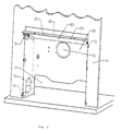
- FIG. 2 a cabinet serving as installation space is shown in FIG. 2. Of the Cabinet only a front wall 34 is shown, which is assumed is that the closet is otherwise a largely closed structure.
- the tabs 33 used to fasten the installation box 20 lie on the Front of the front wall 34 and are screwed there. About that Cover plate 23, in particular between the front part 28 and the front wall 34 of the cabinet, a ventilation gap 35 is formed.
- the warm air finally flows under the front part 28 of the cover plate 23 and pulls out warm air due to an injector effect the installation space behind the front wall 34 via the ventilation gap 35 with.
- 20 are in the installation box the ventilation openings 30 and 31 provided, through which relatively cool air flow in through the installation box 20 into the installation space can.
- a blower can be attached to the opening 32 is arranged on the back of the installation box 20, that is to say in the installation space.
- the edge of the opening 32 is curved outwards in order to form a nozzle reach so that the inlet to the fan can be sealed.
- the blower sucks warm air from the heat exchanger through the opening 32 and mixes with warm air drawn in from the installation space.
- the air flow generated by the blower is directed to the desired via a pipe system Position in the caravan. In this case too it is necessary that Fresh air unhindered through the ventilation openings 30, 31 into the installation space can flow in.
- the blower is also the opening 32 z. B. moved further up, must be in the oblique Cover plate 23 an additional inlet tunnel can be integrated.
- warm air is also drawn in, which is drawn from the cover plate 23 via the front part 28 should be derived forward. This increases the temperature in the Installation space, and the manufacturing cost for the box 20 is clear higher.
- the fan is lower than in the embodiment shown installed, the air drawn in by the blower has not yet reached the required level Heat is reached because it only reaches the exhaust gas heat exchanger for a short distance has been conducted.
- Fastening options for the blower are on the rear wall 21 below the opening 32 36 provided on which z.
- an additional electric heater can be attached to the air flow in addition to the exhaust gas heat exchanger warmed up.
- FIG. 4 shows an enlarged detail of part of FIG. 2, but with one modified embodiment of the invention.
- FIG. 4 differs from that shown in FIG. 2 Embodiment of the heating arrangement according to the invention that a corner of the front part 28 of the cover plate 23 - similar to a "donkey's ear" - Is bent obliquely downwards, whereby a flow wing 40 is formed becomes.
- On the other side of the front part, not shown in FIG. 4 28 is also a part bent in a symmetrical manner. With the two Flow wings 40 it is possible to flow from bottom to top Guide hot air flow to the center of the installation box 20, which creates a certain Concentration of the warm air flow occurs.
Landscapes
- Engineering & Computer Science (AREA)
- Physics & Mathematics (AREA)
- Thermal Sciences (AREA)
- Chemical & Material Sciences (AREA)
- Combustion & Propulsion (AREA)
- Mechanical Engineering (AREA)
- General Engineering & Computer Science (AREA)
- Housings, Intake/Discharge, And Installation Of Fluid Heaters (AREA)
- Domestic Hot-Water Supply Systems And Details Of Heating Systems (AREA)
Applications Claiming Priority (2)
| Application Number | Priority Date | Filing Date | Title |
|---|---|---|---|
| DE2000110085 DE10010085C2 (de) | 2000-03-02 | 2000-03-02 | Heizungsanordnung mit einem Einbaukasten für einen Wärmetauscher |
| DE10010085 | 2000-03-02 |
Publications (3)
| Publication Number | Publication Date |
|---|---|
| EP1130338A2 true EP1130338A2 (fr) | 2001-09-05 |
| EP1130338A3 EP1130338A3 (fr) | 2003-04-09 |
| EP1130338B1 EP1130338B1 (fr) | 2006-05-17 |
Family
ID=7633181
Family Applications (1)
| Application Number | Title | Priority Date | Filing Date |
|---|---|---|---|
| EP20010104997 Expired - Lifetime EP1130338B1 (fr) | 2000-03-02 | 2001-03-01 | Appareil de chauffage avec boîte encastrée pour un échangeur de chaleur |
Country Status (2)
| Country | Link |
|---|---|
| EP (1) | EP1130338B1 (fr) |
| DE (1) | DE10010085C2 (fr) |
Cited By (1)
| Publication number | Priority date | Publication date | Assignee | Title |
|---|---|---|---|---|
| FR3080910A1 (fr) * | 2018-05-02 | 2019-11-08 | Robert Bosch Gmbh | Systeme de dosseret pour l'installation d'une chaudiere a gaz a condensation |
Families Citing this family (4)
| Publication number | Priority date | Publication date | Assignee | Title |
|---|---|---|---|---|
| AU201712794S (en) | 2016-11-23 | 2017-05-23 | Dometic Sweden Ab | Ventilation and air conditioning apparatus |
| DE112018005883B4 (de) | 2017-11-16 | 2025-12-18 | Dometic Sweden Ab | Klimatisierungsvorrichtung für Wohnmobile, Wohnmobil und Verfahren zur Zufuhr von klimatisierter Luft in einem Wohnmobil |
| USD905217S1 (en) | 2018-09-05 | 2020-12-15 | Dometic Sweden Ab | Air conditioning apparatus |
| IT201900019193A1 (it) | 2019-10-17 | 2021-04-17 | Dometic Sweden Ab | Apparato di condizionamento dell'aria per veicoli ricreativi |
Citations (1)
| Publication number | Priority date | Publication date | Assignee | Title |
|---|---|---|---|---|
| DE1959286U (de) | 1967-01-05 | 1967-04-27 | Erich Gross | Einbaurahmen. |
Family Cites Families (3)
| Publication number | Priority date | Publication date | Assignee | Title |
|---|---|---|---|---|
| DE1959286A1 (de) * | 1968-12-03 | 1970-06-18 | Cartigliano Ind Metalmecc | Vakuumtrockenvorrichtung fuer tierische Haeute od.dgl. |
| DE3118052A1 (de) * | 1979-12-14 | 1982-12-16 | Günter Dipl.-Architekt 6096 Raunheim Hack | Lueftungseinrichtung |
| GB2280950A (en) * | 1993-07-31 | 1995-02-15 | Oakline Manufacturing Limited | Storage heater |
-
2000
- 2000-03-02 DE DE2000110085 patent/DE10010085C2/de not_active Expired - Lifetime
-
2001
- 2001-03-01 EP EP20010104997 patent/EP1130338B1/fr not_active Expired - Lifetime
Patent Citations (1)
| Publication number | Priority date | Publication date | Assignee | Title |
|---|---|---|---|---|
| DE1959286U (de) | 1967-01-05 | 1967-04-27 | Erich Gross | Einbaurahmen. |
Cited By (1)
| Publication number | Priority date | Publication date | Assignee | Title |
|---|---|---|---|---|
| FR3080910A1 (fr) * | 2018-05-02 | 2019-11-08 | Robert Bosch Gmbh | Systeme de dosseret pour l'installation d'une chaudiere a gaz a condensation |
Also Published As
| Publication number | Publication date |
|---|---|
| DE10010085C2 (de) | 2002-06-06 |
| EP1130338B1 (fr) | 2006-05-17 |
| EP1130338A3 (fr) | 2003-04-09 |
| DE10010085A1 (de) | 2001-11-22 |
Similar Documents
| Publication | Publication Date | Title |
|---|---|---|
| EP1053663B1 (fr) | Armoire de distribution munie de dispositifs pour refroidir l'air chaud present a l'interieur | |
| DE69313811T2 (de) | Armaturenbrett für Fahrzeuge mit integriertem Wärmetauscher | |
| DE102008053958B4 (de) | Kühlanordnung für einen Schaltschrank | |
| EP1816402B1 (fr) | Four | |
| DE10223085B4 (de) | Einrichtung zum Heizen und/oder Kühlen eines Raumes | |
| EP1130338A2 (fr) | Appareil de chauffage avec boíte encastrée pour un échangeur de chaleur | |
| EP1462730B1 (fr) | Dispositif pour créer un rideau d'air | |
| DE4016563A1 (de) | Auslass | |
| EP1816411A2 (fr) | Dispositif de chauffage d'espace pour une caravane | |
| DE19525945C2 (de) | Verfahren und Vorrichtung zur Erzeugung behaglicher Raumluftzustände | |
| DE60121825T2 (de) | Luftverteilungskappe für einen konvektor | |
| AT411101B (de) | Lüftungsgerät | |
| DE3914242C2 (de) | Einrichtung zum Erwärmen und/oder Kühlen von Räumen | |
| EP2916078B1 (fr) | Radiateur | |
| EP3809053A1 (fr) | Agencement de contrôle climatique et espace | |
| EP3921580B1 (fr) | Système d'aération d'espaces | |
| DE202008010063U1 (de) | Lufttechnische Einrichtung | |
| EP3287711A1 (fr) | Chauffage à air chaud | |
| DE29518108U1 (de) | Gerät zur Belüftung von Räumen | |
| EP0807791B1 (fr) | Système de ventilation pour les pièces d'un bâtiment | |
| DE10016091C5 (de) | Hohlwand | |
| EP2148144B1 (fr) | Dispositif d'aération | |
| DE10215596B4 (de) | Raum-Aufheizeinheit | |
| CH667357A5 (de) | Raumheizgeraet. | |
| DE602004000564T2 (de) | Heizvorrichtung |
Legal Events
| Date | Code | Title | Description |
|---|---|---|---|
| PUAI | Public reference made under article 153(3) epc to a published international application that has entered the european phase |
Free format text: ORIGINAL CODE: 0009012 |
|
| AK | Designated contracting states |
Kind code of ref document: A2 Designated state(s): AT BE CH CY DE DK ES FI FR GB GR IE IT LI LU MC NL PT SE TR |
|
| AX | Request for extension of the european patent |
Free format text: AL;LT;LV;MK;RO;SI |
|
| PUAL | Search report despatched |
Free format text: ORIGINAL CODE: 0009013 |
|
| AK | Designated contracting states |
Kind code of ref document: A3 Designated state(s): AT BE CH CY DE DK ES FI FR GB GR IE IT LI LU MC NL PT SE TR |
|
| AX | Request for extension of the european patent |
Extension state: AL LT LV MK RO SI |
|
| 17P | Request for examination filed |
Effective date: 20030515 |
|
| AKX | Designation fees paid |
Designated state(s): FR GB IT NL |
|
| REG | Reference to a national code |
Ref country code: DE Ref legal event code: 8566 |
|
| 17Q | First examination report despatched |
Effective date: 20040831 |
|
| GRAP | Despatch of communication of intention to grant a patent |
Free format text: ORIGINAL CODE: EPIDOSNIGR1 |
|
| GRAS | Grant fee paid |
Free format text: ORIGINAL CODE: EPIDOSNIGR3 |
|
| GRAA | (expected) grant |
Free format text: ORIGINAL CODE: 0009210 |
|
| AK | Designated contracting states |
Kind code of ref document: B1 Designated state(s): FR GB IT NL |
|
| PG25 | Lapsed in a contracting state [announced via postgrant information from national office to epo] |
Ref country code: IT Free format text: LAPSE BECAUSE OF FAILURE TO SUBMIT A TRANSLATION OF THE DESCRIPTION OR TO PAY THE FEE WITHIN THE PRESCRIBED TIME-LIMIT;WARNING: LAPSES OF ITALIAN PATENTS WITH EFFECTIVE DATE BEFORE 2007 MAY HAVE OCCURRED AT ANY TIME BEFORE 2007. THE CORRECT EFFECTIVE DATE MAY BE DIFFERENT FROM THE ONE RECORDED. Effective date: 20060517 |
|
| REG | Reference to a national code |
Ref country code: GB Ref legal event code: FG4D Free format text: NOT ENGLISH |
|
| GBT | Gb: translation of ep patent filed (gb section 77(6)(a)/1977) |
Effective date: 20060525 |
|
| ET | Fr: translation filed | ||
| PLBE | No opposition filed within time limit |
Free format text: ORIGINAL CODE: 0009261 |
|
| STAA | Information on the status of an ep patent application or granted ep patent |
Free format text: STATUS: NO OPPOSITION FILED WITHIN TIME LIMIT |
|
| 26N | No opposition filed |
Effective date: 20070220 |
|
| REG | Reference to a national code |
Ref country code: FR Ref legal event code: PLFP Year of fee payment: 16 |
|
| REG | Reference to a national code |
Ref country code: FR Ref legal event code: PLFP Year of fee payment: 17 |
|
| REG | Reference to a national code |
Ref country code: FR Ref legal event code: PLFP Year of fee payment: 18 |
|
| PGFP | Annual fee paid to national office [announced via postgrant information from national office to epo] |
Ref country code: NL Payment date: 20200323 Year of fee payment: 20 Ref country code: GB Payment date: 20200325 Year of fee payment: 20 Ref country code: IT Payment date: 20200325 Year of fee payment: 20 |
|
| PGFP | Annual fee paid to national office [announced via postgrant information from national office to epo] |
Ref country code: FR Payment date: 20200324 Year of fee payment: 20 |
|
| REG | Reference to a national code |
Ref country code: NL Ref legal event code: MK Effective date: 20210228 |
|
| REG | Reference to a national code |
Ref country code: GB Ref legal event code: PE20 Expiry date: 20210228 |
|
| PG25 | Lapsed in a contracting state [announced via postgrant information from national office to epo] |
Ref country code: GB Free format text: LAPSE BECAUSE OF EXPIRATION OF PROTECTION Effective date: 20210228 |