EP1130342A2 - Module pour installation de chauffage compacte - Google Patents
Module pour installation de chauffage compacte Download PDFInfo
- Publication number
- EP1130342A2 EP1130342A2 EP01103726A EP01103726A EP1130342A2 EP 1130342 A2 EP1130342 A2 EP 1130342A2 EP 01103726 A EP01103726 A EP 01103726A EP 01103726 A EP01103726 A EP 01103726A EP 1130342 A2 EP1130342 A2 EP 1130342A2
- Authority
- EP
- European Patent Office
- Prior art keywords
- housing
- connections
- assembly according
- heat exchanger
- pump
- Prior art date
- Legal status (The legal status is an assumption and is not a legal conclusion. Google has not performed a legal analysis and makes no representation as to the accuracy of the status listed.)
- Granted
Links
- 238000010438 heat treatment Methods 0.000 title claims abstract description 34
- 238000009434 installation Methods 0.000 title description 2
- XLYOFNOQVPJJNP-UHFFFAOYSA-N water Substances O XLYOFNOQVPJJNP-UHFFFAOYSA-N 0.000 claims abstract description 13
- 238000002347 injection Methods 0.000 claims description 5
- 239000007924 injection Substances 0.000 claims description 5
- 238000002360 preparation method Methods 0.000 claims 1
- 238000002485 combustion reaction Methods 0.000 description 9
- 238000010276 construction Methods 0.000 description 7
- 238000004519 manufacturing process Methods 0.000 description 5
- 238000010586 diagram Methods 0.000 description 3
- 230000002349 favourable effect Effects 0.000 description 2
- 239000002184 metal Substances 0.000 description 2
- LYKJEJVAXSGWAJ-UHFFFAOYSA-N compactone Natural products CC1(C)CCCC2(C)C1CC(=O)C3(O)CC(C)(CCC23)C=C LYKJEJVAXSGWAJ-UHFFFAOYSA-N 0.000 description 1
- 230000000052 comparative effect Effects 0.000 description 1
- 238000005553 drilling Methods 0.000 description 1
- 239000008236 heating water Substances 0.000 description 1
- 239000008235 industrial water Substances 0.000 description 1
- 230000010354 integration Effects 0.000 description 1
- 230000008018 melting Effects 0.000 description 1
- 238000002844 melting Methods 0.000 description 1
Images




Classifications
-
- F—MECHANICAL ENGINEERING; LIGHTING; HEATING; WEAPONS; BLASTING
- F24—HEATING; RANGES; VENTILATING
- F24H—FLUID HEATERS, e.g. WATER OR AIR HEATERS, HAVING HEAT-GENERATING MEANS, e.g. HEAT PUMPS, IN GENERAL
- F24H9/00—Details
- F24H9/14—Arrangements for connecting different sections, e.g. in water heaters
-
- F—MECHANICAL ENGINEERING; LIGHTING; HEATING; WEAPONS; BLASTING
- F24—HEATING; RANGES; VENTILATING
- F24H—FLUID HEATERS, e.g. WATER OR AIR HEATERS, HAVING HEAT-GENERATING MEANS, e.g. HEAT PUMPS, IN GENERAL
- F24H9/00—Details
- F24H9/14—Arrangements for connecting different sections, e.g. in water heaters
- F24H9/142—Connecting hydraulic components
-
- F—MECHANICAL ENGINEERING; LIGHTING; HEATING; WEAPONS; BLASTING
- F24—HEATING; RANGES; VENTILATING
- F24H—FLUID HEATERS, e.g. WATER OR AIR HEATERS, HAVING HEAT-GENERATING MEANS, e.g. HEAT PUMPS, IN GENERAL
- F24H9/00—Details
- F24H9/14—Arrangements for connecting different sections, e.g. in water heaters
- F24H9/148—Arrangements of boiler components on a frame or within a casing to build the fluid heater, e.g. boiler
-
- F—MECHANICAL ENGINEERING; LIGHTING; HEATING; WEAPONS; BLASTING
- F24—HEATING; RANGES; VENTILATING
- F24D—DOMESTIC- OR SPACE-HEATING SYSTEMS, e.g. CENTRAL HEATING SYSTEMS; DOMESTIC HOT-WATER SUPPLY SYSTEMS; ELEMENTS OR COMPONENTS THEREFOR
- F24D2200/00—Heat sources or energy sources
- F24D2200/11—Geothermal energy
-
- F—MECHANICAL ENGINEERING; LIGHTING; HEATING; WEAPONS; BLASTING
- F24—HEATING; RANGES; VENTILATING
- F24H—FLUID HEATERS, e.g. WATER OR AIR HEATERS, HAVING HEAT-GENERATING MEANS, e.g. HEAT PUMPS, IN GENERAL
- F24H1/00—Water heaters, e.g. boilers, continuous-flow heaters or water-storage heaters
- F24H1/48—Water heaters for central heating incorporating heaters for domestic water
- F24H1/52—Water heaters for central heating incorporating heaters for domestic water incorporating heat exchangers for domestic water
-
- Y—GENERAL TAGGING OF NEW TECHNOLOGICAL DEVELOPMENTS; GENERAL TAGGING OF CROSS-SECTIONAL TECHNOLOGIES SPANNING OVER SEVERAL SECTIONS OF THE IPC; TECHNICAL SUBJECTS COVERED BY FORMER USPC CROSS-REFERENCE ART COLLECTIONS [XRACs] AND DIGESTS
- Y02—TECHNOLOGIES OR APPLICATIONS FOR MITIGATION OR ADAPTATION AGAINST CLIMATE CHANGE
- Y02B—CLIMATE CHANGE MITIGATION TECHNOLOGIES RELATED TO BUILDINGS, e.g. HOUSING, HOUSE APPLIANCES OR RELATED END-USER APPLICATIONS
- Y02B10/00—Integration of renewable energy sources in buildings
- Y02B10/40—Geothermal heat-pumps
Definitions
- the invention relates to a structural unit for a compact heating system according to the features specified in the preamble of claim 1.
- Such compact heating systems are used either only for space heating or for combined space heating and Water heating. They combine a large number of individual components in a compact housing. While in older constructions the Single element connected individually via pipes, so-called fittings what has been relatively complex has been going on for quite some time increasingly about including the entire piping complex Holder for the individual units such as pumps, valves and the like run as a unit, which usually consists of several injection molded parts is made of plastic. The use of such a unit has the advantage that, especially with large quantities, the manufacturing and assembly costs can be reduced considerably. But it has furthermore the disadvantage that for different systems in the Usually, different units are used, what to do with it causes a variety of tools to be available, which is significant Cost-related.
- a compact heating system of the type mentioned at the outset is from DE 197 51 515 A1 known.
- the assembly described there points to the pump housing subsequent housing on that an air separator, a Switching element and has a central chamber into which the suction mouth the pump opens.
- an adapter housing be provided, which includes other components.
- this unit Because of that seen in the axial direction of the impeller of the pump connect additional housing, this unit has a comparative great depth. In addition, this unit requires one Large number of individual pipes to connect the connections of the assembly. Finally, the designs described there are Essentially only intended and suitable for a special type of gas boiler.
- the object of the invention is to develop a unit of the type mentioned in such a way that the The aforementioned disadvantages are avoided, especially a compact one Unit is obtained for gas boilers of different types is usable and inexpensive to manufacture.
- the basic idea of the present invention is to design the structural unit in such a way that that the pump set, consisting of an electric motor with it connected centrifugal pump, not as in the prior art known, in the axial direction of the pump with further connection housings is populated, but rather between two valve housings is incorporated, these two expediently in the assembled state
- Fitting housing arranged to the right and left of the pump housing each form a pair of rear ports to which either a plate heat exchanger as a secondary heat exchanger immediately is connected or other piping can start, which enables the unit in gas heaters different designs.
- the arrangement enables the valve housing next to the pump housing is so small Depth that z. B. a plate heat exchanger arranged behind it can be or a corresponding piping.
- the structural unit in the area of these four a stiffening plate arranged in pairs rear connections has, as a result, even with a comparatively light construction can achieve a very high stability of the unit.
- this stiffening plate is only used in the applications is needed that does not have a secondary heat exchanger in this area Have thermal baths, because in all other versions this stiffening plate by the plate heat exchanger which is required anyway is formed.
- the plate heat exchanger which is a comparatively heavy and stable component made of metal is thus constructive Element of the unit. So it becomes the stability of the plate heat exchanger specifically used to stiffen the structural unit.
- the assembly is provided with a stiffening plate, this is expediently to be arranged so that the four are arranged in pairs Connections passed through the stiffening plate, i.e. on the back are led out of the stiffening plate.
- an air separator is to be integrated, so it is particularly favorable to have this in the suction-side fitting housing to be arranged, i.e. on the valve body, which is connected to the suction side of the Pump is connected to the line.
- a 2/3 way valve includes, which either the Primary heat exchanger circuit with the heating circuit or the secondary heat exchanger connects, then this valve should preferably be in the pressure-side fitting housing can be arranged.
- the construction is done preferably so that the pressure-side fitting housing is optional can be used with and without a valve so that where such a valve is not required, the same housing parts can be used.
- the compact heating system according to FIG. 1 has a pump unit 1 whose pressure-side connection 2 with a primary heat exchanger 3 is connected to the line.
- the primary heat exchanger 3 is, for example gas-heated and is arranged within a combustion chamber 4 (FIG. 4).
- the The output of the primary heat exchanger 3 is via a 2/3-way valve 10 optionally with a flow 5 of the room heating or the input of a Secondary heat exchanger 6 connected.
- To the lead to lead 5 connects a bypass line 7 in which an adjustable overflow valve 8 is integrated.
- the bypass line 7 opens into a return 9 of the space heating, which as well as the one output of the secondary heat exchanger 6 a suction-side connection 11 of the pump 1 is line-connected.
- the Suction-side connection 11 is also connected to a line Safety valve 12, which when a predetermined pressure is exceeded opens, with a pressure compensation vessel 13 and a pressure switch 14, which switches off the system when the pressure falls below a predetermined pressure.
- the secondary heat exchanger 6 is on its heat-absorbing side connected to the water supply network 15 of the house.
- the output side Connection 16 leads to the hot water tap.
- a Flow sensor 17 integrated, the signal of which switches the 2/3-way valve.
- the Function of such a heating system is well known, so it is not described in detail here. 4 and 5
- the unit shown includes all of the components described above Except for the primary heat exchanger 3 and the expansion tank 13.
- the compact heating system according to FIG. 2 differs from that described above in that the domestic water heating is not in the secondary heat exchanger 6 takes place, but within a combined Heat exchanger 18, which is arranged within the combustion chamber 4 is.
- the function of this compact heating system corresponds to that based on Fig. 1 described above.
- the unit is constructed accordingly however, the secondary heat exchanger on the assembly is omitted and is instead arranged in the combustion chamber.
- FIG. 4 shows an example of the structure of a compact heating system. It has a support frame 20 which is provided for wall mounting is. The building connection lines are from below introduced.
- the combustion chamber takes the upper and front area 4 a, which is usually designed as a self-contained housing.
- the pressure equalization vessel 13 is located behind the combustion chamber 4.
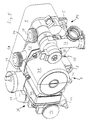
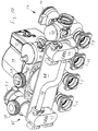
- the structural unit in question is arranged under the combustion chamber 4, which is shown in detail with reference to FIGS. 5 to 9.
- In the presentation 4 are sections of the for the sake of clarity Unit leading to the primary heat exchanger lines, in particular not shown in the area of the connections of the structural unit.
- the pump unit 1 is from which in the figures, the motor housing 21, the pump housing 22 and a terminal box 23 placed on the motor housing 21 is visible are, between a suction-side fitting housing 24 and a pressure-side fitting housing 25 incorporated positively.
- the pump housing 22 has two flat side projections 26 which to engage in projecting from the pump housing 22, from above seen U-shaped and closed down brackets 27 on the Fitting housing 24 and 25 are provided.
- Pump housing 22 on its end face in the lower area with the suction side Fitting housing 24 connected to the line connection to the suction side connection 11 of the pump.
- This connection is on the valve side by the in Figures 6 and 7 within the suction side Armature housing 24 recognizable cross line 28 formed runs immediately behind the pump housing 22.
- the cross line 28 opens into an air separator 29, which is also part of the suction side Armature housing 24 is.
- This cross line 28, which is on its pump side End is open, is closed there in a corresponding closure.
- the line connection within the pump is made via a pipe section provided in the end wall 30 of the pump housing, which opens into the cross line 28.
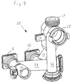
- Each of the valve housings 24, 25 has two rear and one above the other arranged connections 31, 32 and 33, 34 for the secondary heat exchanger 6 in the form of a plate heat exchanger. These connections 31, 32, 33 and 34 can be seen well in Fig. 6, the assembly from behind with the heat exchanger removed.
- the connection 31 provides the inlet connection of the secondary heat exchanger 6 for the Primary heat exchanger 3 acted heating circuit.
- This connection 31 leads to the 2/3-way valve within the pressure-side fitting housing 25, that in the front open end of the substantially parallel is introduced to the impeller axis extending tube section 35.
- This Pipe section 35 meets with a pipe section 36 coming from below together, via a pipe section 37 to a rear connection 5 is guided, which forms the flow connection 5 for space heating.
- a connecting piece 38 opens into the pipe section 35 via a line, not shown, to the output of the primary heat exchanger 3 is connected so that the valve 10 is connected to the connector 38 Line either with the flow connection 5 for the room heating or connects to port 31, which is in the plate heat exchanger 6 opens.
- connection 32 of the connection pair 31, 32 of the pressure side Fitting housing 25 is connected to the connection via a pipe section 39 16 connected, which forms the outlet-side hot water connection.
- the suction-side connection housing 24 has a connection pair 33, 34, of which the lower connection 34 with the one also led out to the rear Connection 15 for the water supply network is connected.
- On the Port 34 is in the secondary heat exchanger 6 to be heated Industrial water introduced. This flows from the port 33 Secondary heat exchanger 6 coming heating water to the intake of the Pump.
- the connection 33 is thus connected to the connection 9 on the rear side.
- Threaded bushings are embedded in the plate heat exchanger 6, which with corresponding holes 40 between the connections 31 and 32 or 33 and 34 in the respective valve body 24 and 25 swear.
- the plate heat exchanger 6 is connected via these holes 40 by means of screws inserted into the bores 40 from the front mechanically fixed to the valve housings 24 and 25. about seals lying in the connections 31 to 34 also become the plate heat exchanger also tightly connected.
- the plate heat exchanger 6 thus also forms a structural component for the structural unit and stabilizes it this.
- all housing parts are the structural unit (pump housing 22, valve housing 24, 25) constructively designed so that they are manufactured as injection molded parts without melting cores can be. Any remaining unused connections will be sealed with appropriate end pieces.
- additional connections of the structural unit due to production such as at the lower end of the tube section 36 or at right end of the pipe section 37, additional units connected such as filters, valves or the like, if so There is a need.
- the air separator 29 is in line connection on the suction-side fitting housing 24 and also a vertically directed one below Pipe section 46, in which the safety valve 12 is incorporated. Further on the cross line is connected to the pressure switch 14, as in particular 5 and 7 can be seen.
- the flow sensor 17 is vertical extending pipe section 47 of the suction-side fitting housing 24 incorporated.
- the unit described above is for installation in a gas boiler provided according to the circuit arrangement of FIG. 1.
- the same unit can, however, remain almost unchanged without such a heat exchanger for gas boilers according to the circuit arrangements according to FIGS. 2 and 3 can be used.
- the heat exchanger 6 instead to provide an inherently rigid plate 48 through which the connections 31 to 34 are passed through.
- connection housing 49 on the back of the plate 48 provided that have threaded bushings and thus a mechanical allow fixed integration of the plate 48 without doing this on the plate to have to attach separate fastening devices.
- Plate 48 can be formed as a simple stamped part from sheet metal, while the Connection housing 49, which are otherwise identical, as injection molded parts are made of plastic.
- Each of the connector housings 49 leads the top connection out of the housing on both sides out and the lower one to one side, as shown in FIG. 10 is.
- valve 10 is removed from the pipe section 35 and this at the end closed by a stopper 51, as shown in Fig. 10 is.
- a corresponding representation in Fig. 6 is for the sake of Simplification of drawings has been made. All orders common is that the pressure port 52 of the pump housing 2 with a to the primary heat exchanger leading line is connected.
- the channel arrangement within the valve body 24 and 25 can be varied according to the connection-side requirements. So is it is expedient, as in the exemplary embodiment, all connections 16, 5, 15, 9 of the assembly on the back in one plane, but can these connections also down or to another direction or can be brought out in a different arrangement if desired.
- connection housings 24 and 25 can also be reversed Arrangement may be provided, d. H. 4 that pressure side connection housing on the left of the pump and that suction-side connection housing on the right side of the pump, without to leave the construction principle according to the invention.
Landscapes
- Engineering & Computer Science (AREA)
- Physics & Mathematics (AREA)
- Thermal Sciences (AREA)
- Chemical & Material Sciences (AREA)
- Combustion & Propulsion (AREA)
- Mechanical Engineering (AREA)
- General Engineering & Computer Science (AREA)
- Steam Or Hot-Water Central Heating Systems (AREA)
- Structures Of Non-Positive Displacement Pumps (AREA)
Applications Claiming Priority (2)
| Application Number | Priority Date | Filing Date | Title |
|---|---|---|---|
| DE2000107873 DE10007873C1 (de) | 2000-02-21 | 2000-02-21 | Baueinheit für eine Kompaktheizungsanlage |
| DE10007873 | 2000-02-21 |
Publications (4)
| Publication Number | Publication Date |
|---|---|
| EP1130342A2 true EP1130342A2 (fr) | 2001-09-05 |
| EP1130342A3 EP1130342A3 (fr) | 2003-04-02 |
| EP1130342B1 EP1130342B1 (fr) | 2005-11-23 |
| EP1130342B2 EP1130342B2 (fr) | 2017-01-18 |
Family
ID=7631725
Family Applications (1)
| Application Number | Title | Priority Date | Filing Date |
|---|---|---|---|
| EP01103726.4A Expired - Lifetime EP1130342B2 (fr) | 2000-02-21 | 2001-02-15 | Module pour installation de chauffage compacte |
Country Status (2)
| Country | Link |
|---|---|
| EP (1) | EP1130342B2 (fr) |
| DE (2) | DE10007873C1 (fr) |
Cited By (5)
| Publication number | Priority date | Publication date | Assignee | Title |
|---|---|---|---|---|
| EP1657507A1 (fr) * | 2004-11-05 | 2006-05-17 | Grundfos A/S | Ensemble pour installation de chauffage compact |
| EP1845314A1 (fr) * | 2006-04-14 | 2007-10-17 | Fugas Spa | Ensemble hydraulique de retour pour chaudière murale |
| EP1847781A3 (fr) * | 2006-04-19 | 2007-12-05 | Fugas Spa | Circuit hydraulique pour système de chauffage d'eau sanitaire et de chauffage alimenté d'une source de chaleur centralisée |
| ITMI20090527A1 (it) * | 2009-04-01 | 2010-10-02 | Gruppo Imar S P A | Modulo di collegamento idraulico alle utenze termiche di un impianto di climatizzazione bivalente ed impianto di climatizzazione includente tale modulo |
| EP1408292B2 (fr) † | 2002-10-07 | 2013-07-31 | Nefit Buderus B.V. | Appareil de chauffage |
Families Citing this family (11)
| Publication number | Priority date | Publication date | Assignee | Title |
|---|---|---|---|---|
| ITBO20010493A1 (it) * | 2001-07-30 | 2003-01-30 | O T M A S N C Di Spaggiari & N | Collettorizzazione ambidestra per circuito idraulico di caldaie murali |
| EP1418387B1 (fr) * | 2002-11-08 | 2016-01-13 | Grundfos A/S | Installation de chauffage compacte avec deux circuits de chauffage |
| ATE397737T1 (de) * | 2003-11-03 | 2008-06-15 | Grundfos As | Baueinheit für eine kompaktheizungsanlage |
| ATE555349T1 (de) * | 2003-11-03 | 2012-05-15 | Grundfos As | Baueinheit für eine kompaktheizungsanlage |
| ITMI20041982A1 (it) * | 2004-10-19 | 2005-01-19 | G V Stamperie S P A | "gruppo caldaia per caldaie a gas a doppia funzione e caldaia con tale gruppo" |
| ITTO20040846A1 (it) * | 2004-12-01 | 2005-03-01 | Cosmogas Srl | Scambiatore di calore per una caldaia di tipo combinato, e caldaia di tipo combinato impiegante tale scambiatore di calore |
| CN102226588B (zh) * | 2011-04-22 | 2014-08-13 | 格伦德福斯管理联合股份公司 | 太阳能工作站 |
| CN102226589B (zh) * | 2011-04-22 | 2013-04-17 | 格伦德福斯管理联合股份公司 | 太阳能工作站 |
| DE202012012516U1 (de) * | 2011-08-16 | 2013-03-01 | Ixetic Bad Homburg Gmbh | Kompaktes Heiz-/Kühlmodul |
| EP3012553B1 (fr) | 2014-10-21 | 2018-01-17 | Grundfos Holding A/S | Composant pour une installation de chauffage |
| SK8153Y1 (sk) | 2017-05-03 | 2018-07-02 | Protherm Production S R O | Konštrukčná jednotka pre hydraulický modul |
Citations (1)
| Publication number | Priority date | Publication date | Assignee | Title |
|---|---|---|---|---|
| DE19751515A1 (de) | 1997-11-21 | 1999-06-10 | Grundfos As | Baueinheit für eine Kompaktheizungsanlage |
Family Cites Families (5)
| Publication number | Priority date | Publication date | Assignee | Title |
|---|---|---|---|---|
| IT1254266B (it) * | 1992-03-12 | 1995-09-14 | Gruppo idraulico perfezionato per impianti misti di riscaldamento e acqua sanitaria | |
| IT230482Y1 (it) * | 1993-11-10 | 1999-06-07 | Beretta A Ing Spa | Gruppo idraulico estremamente compatto per caldaie murali a gas |
| IT1284431B1 (it) * | 1996-03-22 | 1998-05-21 | Fugas Srl | Gruppo idraulico con pompa integrata per impianti misti di riscaldamento e acqua sanitaria |
| DE19632605A1 (de) * | 1996-08-13 | 1998-02-19 | Wilo Gmbh | Hydraulikbaugruppe für eine kombinierte Heizwasser- und Sanitärwasseranlage |
| IT1298069B1 (it) * | 1997-10-20 | 1999-12-20 | Valter Falavegna | Gruppo valvolare a distribuzione idraulica integrale particolarmente per caldaie murali da riscaldamento e produzione di acqua calda |
-
2000
- 2000-02-21 DE DE2000107873 patent/DE10007873C1/de not_active Expired - Lifetime
-
2001
- 2001-02-15 DE DE50108120T patent/DE50108120D1/de not_active Expired - Lifetime
- 2001-02-15 EP EP01103726.4A patent/EP1130342B2/fr not_active Expired - Lifetime
Patent Citations (1)
| Publication number | Priority date | Publication date | Assignee | Title |
|---|---|---|---|---|
| DE19751515A1 (de) | 1997-11-21 | 1999-06-10 | Grundfos As | Baueinheit für eine Kompaktheizungsanlage |
Cited By (5)
| Publication number | Priority date | Publication date | Assignee | Title |
|---|---|---|---|---|
| EP1408292B2 (fr) † | 2002-10-07 | 2013-07-31 | Nefit Buderus B.V. | Appareil de chauffage |
| EP1657507A1 (fr) * | 2004-11-05 | 2006-05-17 | Grundfos A/S | Ensemble pour installation de chauffage compact |
| EP1845314A1 (fr) * | 2006-04-14 | 2007-10-17 | Fugas Spa | Ensemble hydraulique de retour pour chaudière murale |
| EP1847781A3 (fr) * | 2006-04-19 | 2007-12-05 | Fugas Spa | Circuit hydraulique pour système de chauffage d'eau sanitaire et de chauffage alimenté d'une source de chaleur centralisée |
| ITMI20090527A1 (it) * | 2009-04-01 | 2010-10-02 | Gruppo Imar S P A | Modulo di collegamento idraulico alle utenze termiche di un impianto di climatizzazione bivalente ed impianto di climatizzazione includente tale modulo |
Also Published As
| Publication number | Publication date |
|---|---|
| EP1130342B1 (fr) | 2005-11-23 |
| DE10007873C1 (de) | 2001-06-28 |
| EP1130342A3 (fr) | 2003-04-02 |
| DE50108120D1 (de) | 2005-12-29 |
| EP1130342B2 (fr) | 2017-01-18 |
Similar Documents
| Publication | Publication Date | Title |
|---|---|---|
| EP1130342B1 (fr) | Module pour installation de chauffage compacte | |
| EP1528330B1 (fr) | Ensemble pour installation de chauffage compact | |
| CH654390A5 (en) | Distributor, especially for the water in heating systems | |
| EP1528329B1 (fr) | Ensemble pour installation de chauffage compact | |
| EP2093517B1 (fr) | Composant pour installation de chauffage compacte | |
| DE19800487A1 (de) | Röhrenheizkörper mit innerem Rohr | |
| DE19915701C2 (de) | Anschlussgarnitur für einen Plattenheizkörper | |
| DE19912284A1 (de) | Kompaktheizungsanlage | |
| EP1884720A1 (fr) | Ensemble pour installation de chauffage compact | |
| EP1672286B1 (fr) | Distributeur pour un circuit de liquide d'une installation de chauffage | |
| EP3012553B1 (fr) | Composant pour une installation de chauffage | |
| EP1884723B1 (fr) | Module | |
| DE10015645B4 (de) | Wärmetauscher für Brennwertgeräte | |
| DE3533196A1 (de) | Doppelwaermetauscher, insbesondere heizkoerper fuer eine heiz- oder klimaanlage eines kraftfahrzeugs | |
| DE29915384U1 (de) | Kombination aus einer Haupteinheit und wenigstens einer Anbau-Funktionseinheit | |
| DE10102022A1 (de) | Wasserheizanlage | |
| DE19750109A1 (de) | Anschlußgarnitur und Heizkörper | |
| EP2629019B1 (fr) | Unité de boîtier pour un appareil de chauffage | |
| DE10005668B4 (de) | Röhrenheizkörper mit umlaufenden Heizröhren | |
| DE10341002A1 (de) | Verrohrungssystem | |
| AT410024B (de) | Wasserheizanlage | |
| AT404068B (de) | Heizungsventil, insbesondere für eine einrohrheizungsanlage | |
| EP1235035A2 (fr) | Distributeur | |
| DE102024112888A1 (de) | Konnektorblock für eine Fluidleitungsstruktur sowie Fluidleitungsstruktur eines modularen Temperiersystems | |
| DE19711085A1 (de) | Drei- oder Vier-Wegeventil und Adapterstück |
Legal Events
| Date | Code | Title | Description |
|---|---|---|---|
| PUAI | Public reference made under article 153(3) epc to a published international application that has entered the european phase |
Free format text: ORIGINAL CODE: 0009012 |
|
| AK | Designated contracting states |
Kind code of ref document: A2 Designated state(s): AT BE CH CY DE DK ES FI FR GB GR IE IT LI LU MC NL PT SE TR |
|
| AX | Request for extension of the european patent |
Free format text: AL;LT;LV;MK;RO;SI |
|
| PUAL | Search report despatched |
Free format text: ORIGINAL CODE: 0009013 |
|
| AK | Designated contracting states |
Kind code of ref document: A3 Designated state(s): AT BE CH CY DE DK ES FI FR GB GR IE IT LI LU MC NL PT SE TR |
|
| AX | Request for extension of the european patent |
Extension state: AL LT LV MK RO SI |
|
| 17P | Request for examination filed |
Effective date: 20030401 |
|
| AKX | Designation fees paid |
Designated state(s): DE FR GB IT |
|
| GRAP | Despatch of communication of intention to grant a patent |
Free format text: ORIGINAL CODE: EPIDOSNIGR1 |
|
| GRAS | Grant fee paid |
Free format text: ORIGINAL CODE: EPIDOSNIGR3 |
|
| GRAA | (expected) grant |
Free format text: ORIGINAL CODE: 0009210 |
|
| AK | Designated contracting states |
Kind code of ref document: B1 Designated state(s): DE FR GB IT |
|
| REG | Reference to a national code |
Ref country code: GB Ref legal event code: FG4D Free format text: NOT ENGLISH |
|
| REF | Corresponds to: |
Ref document number: 50108120 Country of ref document: DE Date of ref document: 20051229 Kind code of ref document: P |
|
| GBT | Gb: translation of ep patent filed (gb section 77(6)(a)/1977) |
Effective date: 20060111 |
|
| ET | Fr: translation filed | ||
| PLBI | Opposition filed |
Free format text: ORIGINAL CODE: 0009260 |
|
| PLBI | Opposition filed |
Free format text: ORIGINAL CODE: 0009260 |
|
| PLAX | Notice of opposition and request to file observation + time limit sent |
Free format text: ORIGINAL CODE: EPIDOSNOBS2 |
|
| 26 | Opposition filed |
Opponent name: WILO AG Effective date: 20060822 |
|
| 26 | Opposition filed |
Opponent name: O.T.M.A. SNC DI SPAGGIARI E NASI Effective date: 20060823 Opponent name: WILO AG Effective date: 20060822 |
|
| PLAF | Information modified related to communication of a notice of opposition and request to file observations + time limit |
Free format text: ORIGINAL CODE: EPIDOSCOBS2 |
|
| PLBB | Reply of patent proprietor to notice(s) of opposition received |
Free format text: ORIGINAL CODE: EPIDOSNOBS3 |
|
| PLAY | Examination report in opposition despatched + time limit |
Free format text: ORIGINAL CODE: EPIDOSNORE2 |
|
| PLBC | Reply to examination report in opposition received |
Free format text: ORIGINAL CODE: EPIDOSNORE3 |
|
| APBM | Appeal reference recorded |
Free format text: ORIGINAL CODE: EPIDOSNREFNO |
|
| APBP | Date of receipt of notice of appeal recorded |
Free format text: ORIGINAL CODE: EPIDOSNNOA2O |
|
| APAH | Appeal reference modified |
Free format text: ORIGINAL CODE: EPIDOSCREFNO |
|
| APBM | Appeal reference recorded |
Free format text: ORIGINAL CODE: EPIDOSNREFNO |
|
| APBP | Date of receipt of notice of appeal recorded |
Free format text: ORIGINAL CODE: EPIDOSNNOA2O |
|
| APBM | Appeal reference recorded |
Free format text: ORIGINAL CODE: EPIDOSNREFNO |
|
| APBP | Date of receipt of notice of appeal recorded |
Free format text: ORIGINAL CODE: EPIDOSNNOA2O |
|
| PLAB | Opposition data, opponent's data or that of the opponent's representative modified |
Free format text: ORIGINAL CODE: 0009299OPPO |
|
| APBQ | Date of receipt of statement of grounds of appeal recorded |
Free format text: ORIGINAL CODE: EPIDOSNNOA3O |
|
| APBQ | Date of receipt of statement of grounds of appeal recorded |
Free format text: ORIGINAL CODE: EPIDOSNNOA3O |
|
| R26 | Opposition filed (corrected) |
Opponent name: WILO SE Effective date: 20060822 Opponent name: O.T.M.A. SNC DI SPAGGIARI E C. Effective date: 20060823 |
|
| APBQ | Date of receipt of statement of grounds of appeal recorded |
Free format text: ORIGINAL CODE: EPIDOSNNOA3O |
|
| REG | Reference to a national code |
Ref country code: FR Ref legal event code: PLFP Year of fee payment: 16 |
|
| APBU | Appeal procedure closed |
Free format text: ORIGINAL CODE: EPIDOSNNOA9O |
|
| PUAH | Patent maintained in amended form |
Free format text: ORIGINAL CODE: 0009272 |
|
| STAA | Information on the status of an ep patent application or granted ep patent |
Free format text: STATUS: PATENT MAINTAINED AS AMENDED |
|
| REG | Reference to a national code |
Ref country code: FR Ref legal event code: PLFP Year of fee payment: 17 |
|
| 27A | Patent maintained in amended form |
Effective date: 20170118 |
|
| AK | Designated contracting states |
Kind code of ref document: B2 Designated state(s): DE FR GB IT |
|
| REG | Reference to a national code |
Ref country code: DE Ref legal event code: R102 Ref document number: 50108120 Country of ref document: DE |
|
| REG | Reference to a national code |
Ref country code: FR Ref legal event code: PLFP Year of fee payment: 18 |
|
| PGFP | Annual fee paid to national office [announced via postgrant information from national office to epo] |
Ref country code: DE Payment date: 20200226 Year of fee payment: 20 Ref country code: IT Payment date: 20200221 Year of fee payment: 20 Ref country code: GB Payment date: 20200225 Year of fee payment: 20 |
|
| PGFP | Annual fee paid to national office [announced via postgrant information from national office to epo] |
Ref country code: FR Payment date: 20200220 Year of fee payment: 20 |
|
| REG | Reference to a national code |
Ref country code: DE Ref legal event code: R071 Ref document number: 50108120 Country of ref document: DE |
|
| REG | Reference to a national code |
Ref country code: GB Ref legal event code: PE20 Expiry date: 20210214 |
|
| PG25 | Lapsed in a contracting state [announced via postgrant information from national office to epo] |
Ref country code: GB Free format text: LAPSE BECAUSE OF EXPIRATION OF PROTECTION Effective date: 20210214 |