EP1845314A1 - Ensemble hydraulique de retour pour chaudière murale - Google Patents
Ensemble hydraulique de retour pour chaudière murale Download PDFInfo
- Publication number
- EP1845314A1 EP1845314A1 EP07106133A EP07106133A EP1845314A1 EP 1845314 A1 EP1845314 A1 EP 1845314A1 EP 07106133 A EP07106133 A EP 07106133A EP 07106133 A EP07106133 A EP 07106133A EP 1845314 A1 EP1845314 A1 EP 1845314A1
- Authority
- EP
- European Patent Office
- Prior art keywords
- subgroup
- water
- return
- unit
- heating
- Prior art date
- Legal status (The legal status is an assumption and is not a legal conclusion. Google has not performed a legal analysis and makes no representation as to the accuracy of the status listed.)
- Withdrawn
Links
- XLYOFNOQVPJJNP-UHFFFAOYSA-N water Substances O XLYOFNOQVPJJNP-UHFFFAOYSA-N 0.000 claims abstract description 37
- 239000002184 metal Substances 0.000 claims abstract description 12
- 239000002131 composite material Substances 0.000 claims abstract description 8
- 238000010438 heat treatment Methods 0.000 claims abstract description 8
- JEGUKCSWCFPDGT-UHFFFAOYSA-N h2o hydrate Chemical compound O.O JEGUKCSWCFPDGT-UHFFFAOYSA-N 0.000 claims abstract description 3
- 229910001369 Brass Inorganic materials 0.000 claims description 11
- 239000010951 brass Substances 0.000 claims description 11
- 238000010276 construction Methods 0.000 claims description 4
- 239000003365 glass fiber Substances 0.000 claims description 3
- 239000008236 heating water Substances 0.000 claims 4
- 239000007769 metal material Substances 0.000 description 5
- 230000006872 improvement Effects 0.000 description 3
- 239000000463 material Substances 0.000 description 3
- 230000008901 benefit Effects 0.000 description 2
- 230000004048 modification Effects 0.000 description 2
- 238000012986 modification Methods 0.000 description 2
- 239000004033 plastic Substances 0.000 description 2
- 229920003023 plastic Polymers 0.000 description 2
- 230000009467 reduction Effects 0.000 description 2
- 230000006735 deficit Effects 0.000 description 1
- 230000001419 dependent effect Effects 0.000 description 1
- 238000010586 diagram Methods 0.000 description 1
- 239000000945 filler Substances 0.000 description 1
- 239000013585 weight reducing agent Substances 0.000 description 1
Images

Classifications
-
- F—MECHANICAL ENGINEERING; LIGHTING; HEATING; WEAPONS; BLASTING
- F24—HEATING; RANGES; VENTILATING
- F24H—FLUID HEATERS, e.g. WATER OR AIR HEATERS, HAVING HEAT-GENERATING MEANS, e.g. HEAT PUMPS, IN GENERAL
- F24H9/00—Details
- F24H9/14—Arrangements for connecting different sections, e.g. in water heaters
-
- F—MECHANICAL ENGINEERING; LIGHTING; HEATING; WEAPONS; BLASTING
- F24—HEATING; RANGES; VENTILATING
- F24H—FLUID HEATERS, e.g. WATER OR AIR HEATERS, HAVING HEAT-GENERATING MEANS, e.g. HEAT PUMPS, IN GENERAL
- F24H9/00—Details
- F24H9/14—Arrangements for connecting different sections, e.g. in water heaters
- F24H9/142—Connecting hydraulic components
- F24H9/144—Valve seats, piping and heat exchanger connections integrated into a one-piece hydraulic unit
-
- F—MECHANICAL ENGINEERING; LIGHTING; HEATING; WEAPONS; BLASTING
- F24—HEATING; RANGES; VENTILATING
- F24D—DOMESTIC- OR SPACE-HEATING SYSTEMS, e.g. CENTRAL HEATING SYSTEMS; DOMESTIC HOT-WATER SUPPLY SYSTEMS; ELEMENTS OR COMPONENTS THEREFOR
- F24D3/00—Hot-water central heating systems
- F24D3/08—Hot-water central heating systems in combination with systems for domestic hot-water supply
-
- F—MECHANICAL ENGINEERING; LIGHTING; HEATING; WEAPONS; BLASTING
- F24—HEATING; RANGES; VENTILATING
- F24H—FLUID HEATERS, e.g. WATER OR AIR HEATERS, HAVING HEAT-GENERATING MEANS, e.g. HEAT PUMPS, IN GENERAL
- F24H1/00—Water heaters, e.g. boilers, continuous-flow heaters or water-storage heaters
- F24H1/48—Water heaters for central heating incorporating heaters for domestic water
- F24H1/52—Water heaters for central heating incorporating heaters for domestic water incorporating heat exchangers for domestic water
Definitions
- the present invention relates to residential mixed systems adapted to supply both heating and sanitary water, i.e. systems in which the hot water from one or different supplies is used both for heating dwellings through radiator elements (heaters) and for producing sanitary warm water for several uses.
- the primary hot water can be supplied either by a local gas burner, or by a centralized plant or by a station of a district heating system.
- a hydraulic group of this kind comprises a delivery subgroup and a return subgroup connected to a water/water heat exchanger of the type comprising a plurality of plates brazed together.
- Fig. 1 of the above mentioned patent illustrates a hydraulic diagram of a group to which the present invention could be applied.
- the delivery subgroup is formed as a metal block, typically of brass, housing a three-way valve, a connection to the main heat exchanger, a connection to the radiator system, an outlet connection for the sanitary water, two connections to the water/water heat exchanger, as well as seats or recesses for a pressure switch and a bypass valve with associated outlet connections.
- the return subgroup is formed as a metal block, typically of brass, housing a water flow detector that actuates the three-way valve (in the above mentioned patent a pressure drop device, and more recently a flow transducer or meter), a connection to the radiator system, an inlet connection to the sanitary water, an outlet connection to the pump, and the other two connections to the water/water heat exchanger.
- the pump can be embedded in the second subgroup made of plastic material or anyhow secured to the second metal subgroup.
- any constructional improvement affecting only a part of the group might result in being incompatible with the remainder of the group, to the point of requiring the replacement of the whole group.
- the invention further relates to a hydraulic group for a system providing for both heating and sanitary water and equipped with a return subgroup of the above mentioned type.
- unit IIA is made of brass and is preferably a "light weight" unit, i.e. formed with a small amount of metal material
- unit or portion IIB is made of a composite material based on polyammide, i.e. comprising a polymeric base material and at least one filler.
- a preferred material is for instance the one known as PA 6.6 GF30s comprising Polyammyde PA 6.6 filled with a 30% of glass fibers (Glass Fibers GF30).
- Unit or portion IIB is more massive and is formed inside the pump body, or in other words the pump body PC is formed in such way as to incorporate the other group functions such as the three-way valve, the drain tap, the connection to the safety valve, etc. that will be illustrated later on.
- the metal material from which unit IIA is formed is preferably brass (UNI EN 12165 CW617N).
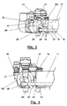
- the brass subgroup IIA is formed as a cylindrical body 11 housing a flow detector 12 of the sanitary water and providing at the opposite end for a connection 13 to the circuit of the sanitary water.
- the flow detector 12 can be either a transducer supplying an output electric signal representative of the flow/no-flow condition, or a device metering the water flow.
- transverse portions 16 and 18 for connecting the water-water heat exchanger to the subgroup, and a tilted portion 19 housing the tap 20 for filling the primary circuit, and also a connection 21 for the connection of the subgroup to unit IIB.
- Portion IIB is substantially made up by the pump body PC and incorporates a three-way routing valve 22 (integrated in the pump body PC), and in accordance with an advantageous embodiment of the invention, this valve extends vertically.
- a drain tap 24 for emptying the plant, a connection 25 (if required) to an external bypass pipe, a connection 26 to a safety valve and a connection 27 for connecting the portion IIB to the above illustrated brass group IIA.
- the advantage of a vertical construction of the routing three-way valve 22 is that of enabling the construction of the inner functional parts of the routing three-way valve as a single component assembled so as to be completely removable (like a sort of "cartridge"). This way the worn parts can be replaced without disassembling the pump or other parts of the plant, and moreover the standard connections are maintained for the actual linear actuators.
- the group according to the invention accomplishes the return subgroup functions partly in the light-weight brass portion or unit IIA (transducer and filling), and partly in the pump body, thus providing for a consistent reduction of the metal material (brass) while nevertheless maintaining all the functional features of a traditional return group.
- the metal (brass) is present in all those parts mostly subjected to water hammers (particularly in the sanitary circuit) where traditionally the composite materials (plastics) would not assure an absolute reliability. Also in this case the distance between the axes of the sanitary and primary return connections 13 and 23 is maintained (65 mms).
- the hydraulic circuit according to the invention is completely interchangeable with the existing ones and allows their advantageous replacement without modifying the parts made of metal plates of the existing boilers.
Landscapes
- Engineering & Computer Science (AREA)
- Physics & Mathematics (AREA)
- Thermal Sciences (AREA)
- Chemical & Material Sciences (AREA)
- Combustion & Propulsion (AREA)
- Mechanical Engineering (AREA)
- General Engineering & Computer Science (AREA)
- Steam Or Hot-Water Central Heating Systems (AREA)
Applications Claiming Priority (1)
| Application Number | Priority Date | Filing Date | Title |
|---|---|---|---|
| ITMI20060751 ITMI20060751A1 (it) | 2006-04-14 | 2006-04-14 | Gruppo idraulico di ritorno per caldaie murali |
Publications (1)
| Publication Number | Publication Date |
|---|---|
| EP1845314A1 true EP1845314A1 (fr) | 2007-10-17 |
Family
ID=38268803
Family Applications (1)
| Application Number | Title | Priority Date | Filing Date |
|---|---|---|---|
| EP07106133A Withdrawn EP1845314A1 (fr) | 2006-04-14 | 2007-04-13 | Ensemble hydraulique de retour pour chaudière murale |
Country Status (2)
| Country | Link |
|---|---|
| EP (1) | EP1845314A1 (fr) |
| IT (1) | ITMI20060751A1 (fr) |
Cited By (3)
| Publication number | Priority date | Publication date | Assignee | Title |
|---|---|---|---|---|
| CN106979612A (zh) * | 2017-04-28 | 2017-07-25 | 广东万和热能科技有限公司 | 壁挂炉 |
| WO2022250636A1 (fr) * | 2021-05-24 | 2022-12-01 | Serdar Plastik Sanayi Ve Ticaret A.Ş. | Dispositif « hydroblock » |
| EP4348128A4 (fr) * | 2021-05-24 | 2025-03-26 | Serdar Plastik Sanayi Ve Ticaret A.S. | Dispositif « hydroblock » |
Citations (10)
| Publication number | Priority date | Publication date | Assignee | Title |
|---|---|---|---|---|
| EP0568122A2 (fr) * | 1992-03-12 | 1993-11-03 | FUGAS s.r.l. | Arrangement de soupape prévu pour installations de chauffage ainsi que pour chauffe-eau domestique |
| EP0652408A1 (fr) * | 1993-11-10 | 1995-05-10 | ING. A. BERETTA S.p.A. | Ensemble hydraulique très compact pour chaudières murales à gaz |
| EP0735332A2 (fr) * | 1995-03-31 | 1996-10-02 | Daewoo Electronics Co., Ltd | Chaudière à gaz |
| EP0797057A2 (fr) * | 1996-03-22 | 1997-09-24 | FUGAS s.r.l. | Ensemble de soupape avec pompe intégrée pour chaudière mixte |
| FR2755752A1 (fr) * | 1996-11-08 | 1998-05-15 | Aries | Module hydraulique pour installation de chauffage central et de production d'eau chaude, et chaudiere equipee d'un tel module |
| EP0911590A2 (fr) * | 1997-10-20 | 1999-04-28 | Valter Falavegna | Unité de soupape avec système de distribution hydraulique integré, en particulier pour chaudières murales mixtes |
| EP1130342A2 (fr) * | 2000-02-21 | 2001-09-05 | Grundfos A/S | Module pour installation de chauffage compacte |
| EP1408292A1 (fr) * | 2002-10-07 | 2004-04-14 | Nefit Buderus B.V. | Appareil de chauffage |
| EP1418387A1 (fr) * | 2002-11-08 | 2004-05-12 | Grundfos a/s | Installation de chauffage compacte avec deux circuits de chauffage |
| EP1528330A1 (fr) * | 2003-11-03 | 2005-05-04 | Grundfos A/S | Ensemble pour installation de chauffage compact |
-
2006
- 2006-04-14 IT ITMI20060751 patent/ITMI20060751A1/it unknown
-
2007
- 2007-04-13 EP EP07106133A patent/EP1845314A1/fr not_active Withdrawn
Patent Citations (10)
| Publication number | Priority date | Publication date | Assignee | Title |
|---|---|---|---|---|
| EP0568122A2 (fr) * | 1992-03-12 | 1993-11-03 | FUGAS s.r.l. | Arrangement de soupape prévu pour installations de chauffage ainsi que pour chauffe-eau domestique |
| EP0652408A1 (fr) * | 1993-11-10 | 1995-05-10 | ING. A. BERETTA S.p.A. | Ensemble hydraulique très compact pour chaudières murales à gaz |
| EP0735332A2 (fr) * | 1995-03-31 | 1996-10-02 | Daewoo Electronics Co., Ltd | Chaudière à gaz |
| EP0797057A2 (fr) * | 1996-03-22 | 1997-09-24 | FUGAS s.r.l. | Ensemble de soupape avec pompe intégrée pour chaudière mixte |
| FR2755752A1 (fr) * | 1996-11-08 | 1998-05-15 | Aries | Module hydraulique pour installation de chauffage central et de production d'eau chaude, et chaudiere equipee d'un tel module |
| EP0911590A2 (fr) * | 1997-10-20 | 1999-04-28 | Valter Falavegna | Unité de soupape avec système de distribution hydraulique integré, en particulier pour chaudières murales mixtes |
| EP1130342A2 (fr) * | 2000-02-21 | 2001-09-05 | Grundfos A/S | Module pour installation de chauffage compacte |
| EP1408292A1 (fr) * | 2002-10-07 | 2004-04-14 | Nefit Buderus B.V. | Appareil de chauffage |
| EP1418387A1 (fr) * | 2002-11-08 | 2004-05-12 | Grundfos a/s | Installation de chauffage compacte avec deux circuits de chauffage |
| EP1528330A1 (fr) * | 2003-11-03 | 2005-05-04 | Grundfos A/S | Ensemble pour installation de chauffage compact |
Cited By (4)
| Publication number | Priority date | Publication date | Assignee | Title |
|---|---|---|---|---|
| CN106979612A (zh) * | 2017-04-28 | 2017-07-25 | 广东万和热能科技有限公司 | 壁挂炉 |
| CN106979612B (zh) * | 2017-04-28 | 2022-12-20 | 广东万和热能科技有限公司 | 壁挂炉 |
| WO2022250636A1 (fr) * | 2021-05-24 | 2022-12-01 | Serdar Plastik Sanayi Ve Ticaret A.Ş. | Dispositif « hydroblock » |
| EP4348128A4 (fr) * | 2021-05-24 | 2025-03-26 | Serdar Plastik Sanayi Ve Ticaret A.S. | Dispositif « hydroblock » |
Also Published As
| Publication number | Publication date |
|---|---|
| ITMI20060751A1 (it) | 2007-10-15 |
Similar Documents
| Publication | Publication Date | Title |
|---|---|---|
| EP0797057B1 (fr) | Ensemble de soupape avec pompe intégrée pour chaudière mixte chauffage / eau sanitaire | |
| DK1832816T3 (en) | Hydraulic device, hydraulic device, hydraulic system and method for using it | |
| US20110038223A1 (en) | Mixing system with water saving function and use thereof | |
| EP0568122B1 (fr) | Arrangement de soupape prévu pour installations de chauffage ainsi que pour chauffe-eau domestique | |
| ITBO20080456A1 (it) | Gruppo idraulico valvolare per caldaie murali | |
| EP1080329B1 (fr) | Dispositif de transfert de chaleur | |
| EP1847781B1 (fr) | Circuit hydraulique pour système de chauffage d'eau sanitaire et de chauffage alimenté d'une source de chaleur centralisée | |
| CN102213462B (zh) | 用于分配加热用水的装置 | |
| EP4108998A1 (fr) | Station de chauffage monolithique avec dérivation | |
| EP0693658A1 (fr) | Arrangement improuvé de soupape prévu pour l'installations de chauffage ainsi que pour chauffe-eau domestique | |
| CZ256097A3 (cs) | Hydraulická konstrukční skupina pro kombinované zařízení na topnou a užitkovou vodu | |
| JP2006112719A (ja) | 蒸気給湯システム | |
| JP2006010259A (ja) | 弁内蔵式給湯回路モジュール | |
| EP0244915A2 (fr) | Circuit hydraulique intégré pour chauffe-eau pour chauffage et eau chaude sanitaire | |
| EP1065447A2 (fr) | Manifold de distribution pour système thermique à circulation forcée | |
| EP1944554A2 (fr) | Unité et procédé de distribution de fluides | |
| RU2411421C2 (ru) | Устройство подсоединения радиатора центрального отопления (варианты) | |
| EP4446661A1 (fr) | Dispositif de distribution d'eau et installation de chauffage pour un bâtiment | |
| EP4502476A1 (fr) | Systèmes de chauffage hybrides | |
| EP4538601A1 (fr) | Système de chauffage et unité d'interface | |
| AU2011202486B2 (en) | Split non-pressurised solar water heating systems | |
| EP1420217B1 (fr) | Echangeur de chaleur à plaques avec des conduits de interconnection composés modulaires, qui sont par là variable en leur langueur, qui join le raccord centré avec le supérieure corps de vanne | |
| EP1965139A2 (fr) | Groupe hydraulique avec deux échangeurs thermiques secondaires pour systèmes de chaudières à gaz | |
| AU731240B2 (en) | Hot water system | |
| DE20209478U1 (de) | Anordnung zur Versorgung mindestens einer Wohneinheit mit Heizungs- und Frischwarmwasser |
Legal Events
| Date | Code | Title | Description |
|---|---|---|---|
| PUAI | Public reference made under article 153(3) epc to a published international application that has entered the european phase |
Free format text: ORIGINAL CODE: 0009012 |
|
| AK | Designated contracting states |
Kind code of ref document: A1 Designated state(s): AT BE BG CH CY CZ DE DK EE ES FI FR GB GR HU IE IS IT LI LT LU LV MC MT NL PL PT RO SE SI SK TR |
|
| AX | Request for extension of the european patent |
Extension state: AL BA HR MK YU |
|
| AKX | Designation fees paid | ||
| REG | Reference to a national code |
Ref country code: DE Ref legal event code: 8566 |
|
| STAA | Information on the status of an ep patent application or granted ep patent |
Free format text: STATUS: THE APPLICATION IS DEEMED TO BE WITHDRAWN |
|
| 18D | Application deemed to be withdrawn |
Effective date: 20080418 |