EP1130478A2 - Appareil de production d' images - Google Patents
Appareil de production d' images Download PDFInfo
- Publication number
- EP1130478A2 EP1130478A2 EP01104608A EP01104608A EP1130478A2 EP 1130478 A2 EP1130478 A2 EP 1130478A2 EP 01104608 A EP01104608 A EP 01104608A EP 01104608 A EP01104608 A EP 01104608A EP 1130478 A2 EP1130478 A2 EP 1130478A2
- Authority
- EP
- European Patent Office
- Prior art keywords
- toner
- particles
- forming apparatus
- image forming
- bearing member
- Prior art date
- Legal status (The legal status is an assumption and is not a legal conclusion. Google has not performed a legal analysis and makes no representation as to the accuracy of the status listed.)
- Withdrawn
Links
Images


Classifications
-
- G—PHYSICS
- G03—PHOTOGRAPHY; CINEMATOGRAPHY; ANALOGOUS TECHNIQUES USING WAVES OTHER THAN OPTICAL WAVES; ELECTROGRAPHY; HOLOGRAPHY
- G03G—ELECTROGRAPHY; ELECTROPHOTOGRAPHY; MAGNETOGRAPHY
- G03G9/00—Developers
- G03G9/08—Developers with toner particles
- G03G9/0819—Developers with toner particles characterised by the dimensions of the particles
-
- G—PHYSICS
- G03—PHOTOGRAPHY; CINEMATOGRAPHY; ANALOGOUS TECHNIQUES USING WAVES OTHER THAN OPTICAL WAVES; ELECTROGRAPHY; HOLOGRAPHY
- G03G—ELECTROGRAPHY; ELECTROPHOTOGRAPHY; MAGNETOGRAPHY
- G03G13/00—Electrographic processes using a charge pattern
- G03G13/14—Transferring a pattern to a second base
- G03G13/16—Transferring a pattern to a second base of a toner pattern, e.g. a powder pattern
-
- G—PHYSICS
- G03—PHOTOGRAPHY; CINEMATOGRAPHY; ANALOGOUS TECHNIQUES USING WAVES OTHER THAN OPTICAL WAVES; ELECTROGRAPHY; HOLOGRAPHY
- G03G—ELECTROGRAPHY; ELECTROPHOTOGRAPHY; MAGNETOGRAPHY
- G03G9/00—Developers
- G03G9/08—Developers with toner particles
- G03G9/0827—Developers with toner particles characterised by their shape, e.g. degree of sphericity
Definitions
- the present invention relates to an image forming apparatus which has an electrostatic image developing toner to develop an electrostatic image in an image forming process, such as electronic photography, electrostatic recording, or electrostatic printing.
- an image forming apparatus which has an electrostatic image developing toner to develop an electrostatic image in an image forming process, such as electronic photography, electrostatic recording, or electrostatic printing.
- Methods for removing residual toner from an electrostatic image bearing member which include a blade cleaning method, a fur brush cleaning method, and a magnetic brush cleaning method, commonly bring a cleaning member into contact with an electrostatic image bearing member.
- contact charging methods have recently been proposed which bring a charging member into contact with the surface of an electrostatic image bearing member to apply a voltage produced by superposing a DC voltage and an AC voltage to the image bearing member. These methods allow a lower voltage to be used, compared with the conventional corona charging method.
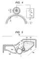
- Contact charging methods also have the advantage of producing a small amount of ozone. For example, as shown in FIG. 4, contact charging methods drive a charging roller 2, or a charging member, which is brought into contact with an electrostatic image bearing member (a photosensitive drum) 1, to apply a voltage (Vac + Vdc) produced by superposing an AC voltage and a DC voltage to the charging roller 2 so that the photosensitive drum 1 can uniformly be charged.
- a voltage Vac + Vdc
- a conventional charging roller is a core around which an electrically conductive elastic member is formed by dispersing carbon in elastic rubber, such as EPDM and NBR.
- the pressure under which the transfer roller is pressed down is reduced, or the transfer material speed and electrostatic image bearing member speed are made to differ from each other to scrape the middle of an image using a shear force and transfer the scraped part onto a transfer material.
- Toners or particles tightly stuck together advantageously prevent a phenomenon called "smeared images with trailing edges": the scattering on a toner image occurs toward the upstream direction of transport due to steam produced by fixing.
- pressure cannot be applied due to the above-described problem of transferred-image quality.
- An object of the present invention is to provide an image forming apparatus which solves the above-described problems.
- Another object of the present invention is to provide an image forming apparatus which forms images free from “hollow images” and blurred images for a long period of time and prevents image deterioration after image transfer.
- Still another object of the present invention is to provide an image forming apparatus which fixes an image using less energy and prevents smeared images with trailing edges during fixing.
- the present invention provides an image forming apparatus, comprising:
- the present invention is based on the following findings made by the inventors through intensive study of the above-described problems of "hollow images” and “blurred images”: (1) using as transferring means a transfer roller which is in contact with the surface of an electrostatic image bearing member and follows the image bearing member as it moves allows transfer roller to be prevented from wearing, (2) using a toner whose particles are 4 to 12 ⁇ m in weight average diameter and have a certain circularity distribution reduces slip resistance between the toner and electrostatic image bearing member, thus preventing hollow images from occurring during image transfer, (3) this advantage also allows an image to be transferred in a pressure range in which an image could not be transferred, preventing blurred images from occurring, (4) a combination of these advantages solves the above-described problems, that is, provides images free from hollow images and blurred images for a long period of time and prevents image deterioration after image transfer, and (5) the combination also allows an image to be fixed using less energy and prevents "smeared images with trailing edges" during fixing.
- the present invention having the above described features can sufficiently exhibit meritorious effects on high speeds and high durability which are highly demanded in recent years.
- Circularity a L 0 L
- the toner according to the present invention its particles are 4 to 12 ⁇ m, preferably 4 to 9 ⁇ m, and more preferably 4 to 8 ⁇ m in weight average diameter and, in the circularity distribution for particles 3 ⁇ m or more in circle-equivalent diameter, particles having a circularity of 0.90 or more are 90% or more, preferably 92% or more, and more preferably 95% or more, based on the number of particles.
- the particles included in the toner are less than 4 ⁇ m in weight average diameter, its fluidity decreases, and its adhesion increases, thus resulting in poor development, transfer, and cleaning performance.
- the particles included in a toner are more than 12 ⁇ m in weight average diameter, a problem arises in image reproduction. If particles 3.17 ⁇ m or less in weight average diameter account for more than 30% of all the particles included in a toner, cleaning performance deteriorates, and fogging are liable to occur.
- the weight average diameter of particles included in a toner according to the present invention is measured using a coulter counter TA-II or a coulter multisizer (made by Coulter Electronic, Inc.).
- a coulter counter TA-II or a coulter multisizer made by Coulter Electronic, Inc.
- first class grade sodium chloride a 1% NaCl solution is prepared as an electrolyte.
- ISOTON R-II from Coulter Scientific Japan
- a dispersant preferably an alkylbenzene sulfonate
- a surface-active agent preferably an alkylbenzene sulfonate
- Circle-equivalent diameter (projected particle area/ ⁇ ) 1/2 ⁇ 2
- Circularity (circumference of circle whose area is equal to projected particle area)/(perimeter of projected particle image) where the "projected particle area” is the binarized area of a toner particle image, and the "perimeter of a projected particle image” is the perimeter of a contour given by connecting edge points on the toner particle image.
- the following methods may be used: (1) a hot-bath method which disperses in water and heats toner particles produced by a grinding method, described later, (2) a method which makes particles spherical by a heat-treating method passing them through hot-air flow or a mechanical-impact method giving them mechanical energy, (3) a method described in Japanese Patent Publication No. 56-13945 or the like which produces spherical toner particles by atomizing a molten mixture in the air using a disk or a multi-fluid nozzle, (4) a method which produces polymerized toner particles using a suspension polymerization method described in Japanese Patent Publication No.
- a method for producing toner particles by grinding comprises the following steps: (1) toner components, such as a binder resin, a colorant, and a release agent or a charge control agent as needed, are uniformly mixed using a mixer, such as a Henshel mixer or a medium disperser, (2) the mixture is kneaded using a kneader, such as a pressurization kneader or an extruder, (3) after cooling the mixture, it is roughly ground using a grinder, such as a hammer mill, (4) the ground mixture is impacted mechanically or under a jet stream against a target, and pulverized to produce toner particles with a desired diameter, and (5) particle size distribution is made sharper.
- a mixer such as a Henshel mixer or a medium disperser
- a kneader such as a pressurization kneader or an extruder
- a grinder such as a hammer mill
- the ground mixture is impacted
- a polymerizing method is preferably used to produce the toner. Specifically, the following method can be used to produce a toner.
- a release agent, a colorant, a charge control agent, a polymerization initiator, and other agents are uniformly dissolved or dispersed in a polymerizable monomer to produce a monomer system. Then the monomer system is dispersed in water containing a dispersion stabilizing agent, using an ordinary stirrer, a homomixer, or a homogenizer. When particles are produced, it is preferable that stirring speed and stirring time are so adjusted that monomer drops are of the same size as desired particles. The mixture has only to be stirred to the extent that the particle state is maintained under the action of the dispersion stabilizing agent and that particles are prevented from sedimenting.
- Polymerization temperature is commonly set at 40°C or more, typically 50 to 90°C.
- the circularity distribution can be controlled according to the type of dispersion stabilizing agent, its amount, stirring capability, pH of water, and polymerization temperature.
- FIG. 1 schematically shows an image forming apparatus of the present invention.
- Reference numeral 1 indicates an electrostatic image bearing member.
- a primary charging apparatus 2 an exposure optical system 3, a developing apparatus 4 with a toner carrier 5, a transferring apparatus 9, and a cleaning apparatus 11 are disposed around the electrostatic image bearing member 1.
- the image forming apparatus uniformly charges the surface of the electrostatic image bearing member 1, a photosensitive member, by the use of the primary charging apparatus 2, and carries out imagewise exposure by the use of the exposure optical system 3 to form an electrostatic latent image on the surface of the electrostatic image bearing member 1.
- a toner coat is formed on the toner carrier 5, which contains a magnet.
- bias applying means 8 a developing unit develops the electrostatic image on the electrostatic image bearing member 1 while applying an alternate bias, a pulse bias, and/or a DC bias between an electrically conductive base of the electrostatic image bearing member 1 and the toner carrier 5.
- a transfer roller 9 is in contact with the electrostatic image bearing member and follows the image bearing member as it moves.
- Bias applying means 10 applies a transfer bias to the transfer roller 9 to impart a charge having a polarity opposite to the polarity of the toner from the back surface of transfer paper P, thus electrostatically transferring the toner image onto the paper P.
- the length of the transfer roller is larger than the width of the transfer paper P (the dimension of the transfer paper P in parallel with the length of the transfer roller, which paper is conveyed during image transfer), the parts of the transfer roller which project beyond the ends of the transfer paper P come in direct contact with the surface of the electrostatic image bearing member, so that driving force provided from the surface of the electrostatic image bearing member as well as driving force provided from the surface of the transfer paper P rotate the transfer roller.
- the transfer roller is rotated in two modes as the electrostatic image bearing member moves: (1) the transfer roller is directly rotated, and (2) the transfer roller is rotated through the transfer paper P.
- a toner produced by a conventional grinding method may often include less than 90% by number of particles with a circularity a of 0.90 or more, so that slip resistance F1 between the toner and a photosensitive drum is almost equal to rolling resistance F2 between toner particles.
- the transfer roller speed must be made to differ from the photosensitive drum speed so that shearing force is produced at the interface between the toner layer and photosensitive drum.
- a conventional image forming apparatus rotates the transfer roller so that its circumferential speed is about 5% higher than that of the photosensitive drum.
- the transfer roller wears due to friction between the roller and transfer material, the outside diameter of the roller decreases, so that the circumferential speed difference is lost, resulting in decrease in the effect on the prevention of hollow images.
- the transfer roller rotates at a speed differing from the speed of the photosensitive drum, and toner and paper dust deposited on the transfer roller act as abrasive, accelerating transfer roller wear.
- the transfer roller is in contact with the electrostatic image bearing member at a pressure of preferably 0.5 to 10 N/cm 2 , and more preferably 0.56 to 2.30 N/cm 2 .
- Fig. 3 shows a relationship between pressure (N/cm 2 ) and bulk density (arbitrary unit).
- region X is a region in which there is no problem of blurred images and smeared images with trailing edges
- region Y is a region in which problems of hollow images (or blank areas) do not occur. If the pressure is less than 0.5 N/cm 2 , a packing force cannot be obtained which is enough to make F2 higher than F1, so that not only do the blur and trailing edges occur, as shown in FIG. 3, but transferability of a toner decreases if its particles have high circularity.
- the pressure is more than 10 N/cm 2 , adhesion between toner particles and the photosensitive drum increases, thus promoting hollow images. It is essential for the pressure to range from 0.5 to 10 N/cm 2 .
- the transfer roller which rotates as the electrostatic image bearing member moves, hardly wears, and thus its outside diameter does not change significantly, so that feed speed is not adversely affected.
- a conventional image forming apparatus has a photosensitive-drum flange integrated with gears, while the image forming apparatus according to the present invention does not need a line of gears which drive the transfer roller. Thus the depth of an image forming apparatus can be reduced.
- the following relationship is established to prevent image aberration and stretched images when the transfer roller rotates as the electrostatic image bearing member moves.
- the surface speed of the transfer roller which is measured using an LV-20Z laser Doppler speedometer is 1% or less lower than that of the photosensitive drum, that is, the circumferential speed of the transfer roller is 99 to 100% of that of the photosensitive drum.
- the radius of the shaft retainer (or a bearing) is made as small as 2 to 4 mm or provided with a ball bearing.
- transfer paper P onto which toner is transferred provides a fixed image.
- Toner which is left after transfer is removed by a cleanering apparatus 11, and then primary charging and subsequent steps are repeated.
- An image forming apparatus of the present invention may be a unit (a process cartridge) as shown in FIG. 5, where the transfer step is not illustrated.
- the unit is comprised of at least a developing means and an electrostatic image bearing member which are integrated into a cartridge.
- the unit may be so adapted as to be detachable from an image forming apparatus body (for example, a copying machine or a laser printer).
- a unit, an assembly of developing means 709, a drum-like electrostatic image bearing member (photosensitive drum)1, a cleaner 708 with cleaning blades 708a, and a primary charger (charging roller) 742 with contact charging means will be described below.
- the developing means 709 has an elastic blade 711 and a toner 710 in a toner container 760.
- the toner 710 is used, and at the time of development, a predetermined electric field is generated between the photosensitive drum 1 and a toner carrier (developing sleeve) 704 by a bias from the bias applying means, so that an image is appropriately developed.
- the distance between the photosensitive drum 1 and developing sleeve 704 is important.
- a transfer roller for an image forming apparatus of the present invention have an Asker-C hardness of 25 to 70.
- a hardness of less than 25 causes the contact area between the transfer roller and photosensitive drum to increase, resulting in apparently reduced transfer roller resistance. Consequently, memory is likely to occur on the drum due to excessive current.
- a hardness of more than 70 causes the contact area between the transfer roller and photosensitive drum to decrease, resulting in apparently increased transfer roller resistance. Consequently, scattering (or black spots around images) tends to occur due to insufficient current at low humidity.
- the roller is preferably produced by covering a core made of iron, SUS, or the like with solid or spongy elastic material, such as EPDM, silicone, NBR, or urethane, containing electrically conductive carbon or an ionic conductivity imparting agent, whose cross-link density, blowing diameter, and filler amount are properly adjusted.
- solid or spongy elastic material such as EPDM, silicone, NBR, or urethane
- the transfer roller is in contact with the electrostatic image bearing member at a pressure of 0.5 to 10 N/cm 2 .
- a pressure of less than 0.5 N/cm 2 tends to cause blurred images or smeared images with trailing edges, and a pressure of more than 10 N/cm 2 tends to cause hollow images during transfer.
- the lower layer of the member is composed preferably of an elastic layer or an electrically conductive layer which is made of thermoplastic elastomer or flexible rubber or that the lower layer is made of electrically conductive sponge.
- the upper layer of the charging member which is in contact with the electrostatic image bearing member preferably has high resistance and is 50 to 200 ⁇ m thick.
- the image bearing member is preferably a lamination consisting of at least an electrically conductive support, a charge generating layer, and a charge transporting layer and has fluorine and/or silicon atoms on the surface.
- the fluororesin used in the present invention is appropriately selected from known fluororesins including, for example, homopolymers and copolymers of tetrafluoroethylene, chlorotrifluoroethylene, hexafluoropropylene, vinyl fluoride, vinylidene fluoride and dichlorodifluoroethylene. Fluorocarbon may also be used for the present invention.
- a fluorine-type polymer or a fluorine-type surface-active agent, a fluorine-type macromonomer, a block polymer or a graft polymer containing a fluorine-type segment produced by copolymerizing a non-fluorine-type polymerizable monomer and a fluorine-containing polymerizable monomer, alone or in combination with the above-described fluororesins.
- the following silicone-type compounds may be used in the present invention: a monomethylsiloxane three-dimensional cross-linked compound, a dimethylcysiloxane-monomethylsiloxane three-dimensional cross-linked compound, ultrahigh-molecular-weight polydimethylsiloxane, a silicone-type surface-active agent, a silicone-type macromonomer, a block polymer or a graft polymer containing polydimethylcyclohexene segment, terminal-modified polydimethylsiloxane, etc.
- Three-dimensional cross-linked compounds whose fine particles have a volume average diameter ranging from 0.01 to 5 ⁇ m can be used for the present invention.
- Polydimethylsiloxane compounds with a molecular weight ranging from 3,000 to 5,000,000 can be preferably used for the present invention.
- Material in fine-particle form is dispersed as a photosensitive layer composition together with a binder resin.
- a fluorine compound and a silicone compound may be preferably used in the present invention if these compounds account for 50% by weight or less of an organic photosensitive layer (OPC) composition. It is more preferable that the compounds account for 0.5 to 50% by weight.
- OPC organic photosensitive layer
- the toner used in the present invention consists of particles 4 to 12 ⁇ m in weight average diameter and includes 90% by number or more of particles with a circularity a of 0.90 or more, so that an image can easily be transferred from the electrostatic image bearing member onto transfer material without hollow images even if there is no difference in speed between the electrostatic image bearing member and transfer roller.
- a high transfer efficiency can be realized and hollow images can be prevented from occurring.
- the toner is packed into paper in a non-heated transfer region, heat conduction is improved in a heated region (preheated region where a fixing film and transfer material are close to each other) by the time a transfer material holding the toner is introduced into a nip, thereby improving fixing performance and preventing smeared images with trailing edges due to steam.
- toner particles Fine hydrophobic silica powder was added to the toner particles to obtain toner I which consisted of particles 6.0 ⁇ m in weight average diameter and included 98% by number or more of particles with a circularity of 0.90 or more.
- the toner contained 2% by number of particles 3.17 ⁇ m or less in diameter.
- Toner I was placed in the development container of a unit.
- the unit was installed in a modified Canon LBP309GII, whose throughput was changed from 16 images/min to 30 images/min, to develop images and evaluate them.
- the processing speed was 200 mm/sec.
- Example used was a transfer roller having a metal core 9a around which an expanded electrically conductive EPDM rubber layer 9b was formed as shown in FIG. 2.
- the transfer roller was 15 mm in outside diameter (the core 9a was 6 mm in diameter, and the layer 9b was 4 mm thick) and had an Asker-C hardness of 30 (this value was the average of 9 values obtained by making 3 measurements each in the middle and at the right and left under a load of 500 g using ASKER-C hardness meter).
- the power-supply side shaft retainer of the transfer roller was 3 mm in radius and made of electrically conductive polyacetal resin, and the sliding part was 3.05 mm or more in radius.
- the non-power-supply side shaft retainer was 3 mm in radius and made of insulating polyacetal resin, and the sliding part was 3.05 mm or more in radius.
- a charging roller which is in contact under a predetermined pressure with a photosensitive drum rotates as the photosensitive drum rotates.
- OPC organic photoconductor
- Changes in the toner image formed was observed as the pressure under which the transfer roller with the electrically conductive elastic layer was in contact with the image was varied from 1 to 80 N/cm 2 .
- the pressure was adjusted by changing nip pressure and spring pressure according to the hardness of the transfer roller.
- the transfer roller was adapted to rotate as the photosensitive drum rotated. To determine the pressure, the nip area is needed. However, the distance between the electrostatic image bearing member and the transfer roller core is measured to compute the pressure, using CAD or the like. For example, a transfer roller 14 mm in diameter which has an Asker-C hardness of 30 is pressed against a photosensitive drum 24 mm in diameter at 10 N in total. Because the width and length of the nip are found to be 4 mm and 220 mm, respectively, the area of the nip and the contact pressure can be calculated. In this case, the pressure is found to be about 1.1 N/cm 2 .
- the image was transferred onto transfer paper by positively charging the paper from behind it, and the image was allowed to pass through a heating/pressurizing apparatus to obtain a fixed image.
- the temperature of a heating roller of the heating/pressurizing apparatus, the total pressure at which the heating and pressurizing rollers were pressed against each other, and the width of the nip were set to be 185°C, 100 N, and 4 mm, respectively.
- An intermittent image forming test was performed under the following environments: (1) 15°C and 10%RH, (2) 23°C and 50%RH, and (3) 32.5°C and 80%RH.
- the print speed was set to be 1 sheet/2 sec.
- the bulk density of the toner is set to be A when not pressurized and to B when transferred, so that the toner is thoroughly packed before entering the fixing apparatus, thereby reducing the thickness of toner deposits and tightly sticking toner particles together.
- fixing performance is defined as a density change divided by the original density, which change is caused by rubbing Silbon C paper against a sample image under a pressure of 0.4 N/cm 2 .
- Transfer efficiency which is defined as follows, was 95% by weight.
- Transfer efficiency (% by weight) [(weight of toner transferred onto transfer material)/(weight of developed toner)] ⁇ 100
- toner particles As is the case with Example 1, fine hydrophobic silica powder was added to the toner particles to produce toner II which consisted of particles 6.0 ⁇ m in weight average diameter and included 85% by number particles with a circularity of 0.90 or more.
- transfer efficiency was found to be 85% by weight or less, and toner use efficiency was found to be excessively low. Because the transfer roller rotated as the electrostatic image bearing member moved, the roller did not satisfactorily prevent hollow images, that is, the roller did not serve the purpose.
- Toner particles II obtained in the same way as in Comparative example 1 were made spherical by mechanically impacting them.
- fine hydrophobic silica powder was added to the toner particles to produce toner III which consisted of particles 6.2 ⁇ m in weight average diameter and included 90% by number particles with a circularity of 0.90 or more.
- transfer efficiency was found to be 92% by weight or more, and toner use efficiency was found to be 85%.
- transfer roller rotated as the electrostatic image bearing member moved the roller satisfactorily prevented hollow images.
- a toner which consisted of particles having the same weight average diameter as the particles of toner I and including 85% by number particles with a circularity of 0.90 or more was used, and the transfer roller was driven so that its surface speed was 1% higher than that of the photosensitive drum.
- transferability increased at a transfer roller contact pressure of 0.6 N/cm 2 or more, and smeared images with trailing edges were reduced at a transfer roller contact pressure of 0.4 N/cm 2 or more.
- rotating the transfer roller as the electrostatic image moves did not provide a range of transfer roller contact pressure which solves all the problems.
- a photosensitive member A made by dispersing fine particles (emulsion-polymerized fine powder 0.32 ⁇ m in volume average diameter) of a fluorine-type resin (a tetrafluoroethylene-hexafluoropropylene copolymer) in the OPC outermost layer was used as an OPC drum.
- the particles accounted for 25% by weight of all OPC layer components.
- a CAPA 700 centrifugal sedimentation particle size distribution meter (from HORIBA, Ltd.) was used to measure the volume average diameter of the fluorine-type resin particles.
- the upper limit pressure for preventing hollow images could be increased up to 15 N/cm 2 .
- the transfer efficiency which is defined by the above-described equation, could be increased to 95% by weight or more as a secondary advantage. Therefore, the volume of the cleaner may be small.
- a transfer roller which has an Asker-C hardness of 50 can be used, solid rubber can be used. This may control the effect of stress on rubber in the process for producing the transfer roller, thereby increasing the productivity. (When rubber is stressed, its resistance typically changes, resulting in unstable resistance.)
- An image forming apparatus in which a specific toner is used, and a transferring means has a transfer roller which is in contact wit the surface of an electrostatic image bearing member and rotates when the electrostatic image bearing member rotates.
- the toner is comprised of particles which have a weight average particle diameter of 4 to 12 ⁇ m, and in a circularity distribution for particles 3 ⁇ m or more in circle-equivalent diameter which are included in the toner, particles having a circularity of 0.90 or more account for 90% by number or more.
Landscapes
- Physics & Mathematics (AREA)
- General Physics & Mathematics (AREA)
- Developing Agents For Electrophotography (AREA)
- Electrostatic Charge, Transfer And Separation In Electrography (AREA)
- Photoreceptors In Electrophotography (AREA)
Applications Claiming Priority (4)
| Application Number | Priority Date | Filing Date | Title |
|---|---|---|---|
| JP2000048436 | 2000-02-25 | ||
| JP2000048436 | 2000-02-25 | ||
| JP2001010300 | 2001-01-18 | ||
| JP2001010300A JP2001312091A (ja) | 2000-02-25 | 2001-01-18 | 画像形成装置 |
Publications (2)
| Publication Number | Publication Date |
|---|---|
| EP1130478A2 true EP1130478A2 (fr) | 2001-09-05 |
| EP1130478A3 EP1130478A3 (fr) | 2003-04-09 |
Family
ID=26586056
Family Applications (1)
| Application Number | Title | Priority Date | Filing Date |
|---|---|---|---|
| EP01104608A Withdrawn EP1130478A3 (fr) | 2000-02-25 | 2001-02-23 | Appareil de production d' images |
Country Status (3)
| Country | Link |
|---|---|
| US (1) | US6424814B2 (fr) |
| EP (1) | EP1130478A3 (fr) |
| JP (1) | JP2001312091A (fr) |
Cited By (1)
| Publication number | Priority date | Publication date | Assignee | Title |
|---|---|---|---|---|
| EP1617299A2 (fr) | 2004-04-26 | 2006-01-18 | Canon Kabushiki Kaisha | Procédé et appareil de formation d'images à grande vitesse ayant une bande de transfert intermédiaire et toner avec la déformation élastique déterminée |
Families Citing this family (2)
| Publication number | Priority date | Publication date | Assignee | Title |
|---|---|---|---|---|
| DE60330448D1 (de) * | 2002-04-10 | 2010-01-21 | Fujifilm Imaging Colorants Ltd | Chemisch hergestellter toner und sein herstellungsverfahren |
| US20050106489A1 (en) * | 2003-11-18 | 2005-05-19 | Canon Kabushiki Kaisha | Image forming apparatus and image forming method |
Family Cites Families (15)
| Publication number | Priority date | Publication date | Assignee | Title |
|---|---|---|---|---|
| US2297691A (en) | 1939-04-04 | 1942-10-06 | Chester F Carlson | Electrophotography |
| US4302093A (en) * | 1979-10-17 | 1981-11-24 | Savin Corporation | Combined transfer and registration system for electrophotographic copier |
| JPS5661842A (en) | 1979-10-24 | 1981-05-27 | Nissan Motor Co Ltd | Receiving device for vehicle |
| JPS56139451A (en) | 1980-04-01 | 1981-10-30 | Tokyo Organ Chem Ind Ltd | Metal complex of metal salt of n-substituted dithiocarbamate, its preparation and chemical for agricultural and industrial use containing the same |
| JPS5953856A (ja) | 1982-09-21 | 1984-03-28 | Canon Inc | トナ−の製造方法 |
| US5159393A (en) * | 1989-08-02 | 1992-10-27 | Canon Kabushiki Kaisha | Image forming apparatus having transfer device and image bearing member traveling at different speeds |
| JPH03202885A (ja) * | 1989-12-28 | 1991-09-04 | Toshiba Corp | 弾性ローラ |
| JP2962919B2 (ja) | 1991-03-01 | 1999-10-12 | キヤノン株式会社 | プロセスカートリッジ及び画像形成装置 |
| US5712072A (en) * | 1995-02-28 | 1998-01-27 | Canon Kabusbiki Kaisha | Toner for developing electrostatic image |
| US5712073A (en) | 1996-01-10 | 1998-01-27 | Canon Kabushiki Kaisha | Toner for developing electrostatic image, apparatus unit and image forming method |
| JP3262505B2 (ja) | 1996-04-18 | 2002-03-04 | キヤノン株式会社 | 静電荷像現像用トナー、装置ユニット及び画像形成方法 |
| US6033817A (en) * | 1996-07-31 | 2000-03-07 | Canon Kabushiki Kaisha | Toner for developing electrostatic image and image forming method |
| EP0869399B1 (fr) * | 1997-04-04 | 2001-08-29 | Canon Kabushiki Kaisha | Révélateur pour la production d'images, procédé de production d'images, et procédé de fixation par chaleur |
| DE69818912T2 (de) * | 1997-06-18 | 2004-08-19 | Canon K.K. | Toner, Zweikomponenten-Entwickler und Bilderzeugungsverfahren |
| US6077636A (en) * | 1998-01-28 | 2000-06-20 | Canon Kabushiki Kaisha | Toner, two-component developer, image forming method and apparatus unit |
-
2001
- 2001-01-18 JP JP2001010300A patent/JP2001312091A/ja not_active Withdrawn
- 2001-02-22 US US09/789,637 patent/US6424814B2/en not_active Expired - Lifetime
- 2001-02-23 EP EP01104608A patent/EP1130478A3/fr not_active Withdrawn
Cited By (3)
| Publication number | Priority date | Publication date | Assignee | Title |
|---|---|---|---|---|
| EP1617299A2 (fr) | 2004-04-26 | 2006-01-18 | Canon Kabushiki Kaisha | Procédé et appareil de formation d'images à grande vitesse ayant une bande de transfert intermédiaire et toner avec la déformation élastique déterminée |
| EP1617299A3 (fr) * | 2004-04-26 | 2006-01-25 | Canon Kabushiki Kaisha | Procédé et appareil de formation d'images à grande vitesse ayant une bande de transfert intermédiaire et toner avec la déformation élastique déterminée |
| US7381515B2 (en) | 2004-04-26 | 2008-06-03 | Canon Kabushiki Kaisha | Image forming method and image forming apparatus |
Also Published As
| Publication number | Publication date |
|---|---|
| US6424814B2 (en) | 2002-07-23 |
| US20020003979A1 (en) | 2002-01-10 |
| EP1130478A3 (fr) | 2003-04-09 |
| JP2001312091A (ja) | 2001-11-09 |
Similar Documents
| Publication | Publication Date | Title |
|---|---|---|
| US5311264A (en) | Developing apparatus for developing electrostatic latent image using one component developer | |
| EP0869399A2 (fr) | Révélateur pour la production d'images, procédé de production d'images, et procédé de fixation par chaleur | |
| JP2007108656A (ja) | 画像形成装置 | |
| JP3576756B2 (ja) | 画像形成装置 | |
| JPH08278673A (ja) | 画像形成方法及び画像形成装置 | |
| US6424814B2 (en) | Image forming apparatus using shaped toner particles and transfer roller pressure for fine image quality | |
| JPH09114129A (ja) | 現像装置 | |
| JP2004325924A (ja) | 画像形成装置 | |
| JP3323741B2 (ja) | 現像剤担持体及び現像剤担持体の製造方法 | |
| US7346300B2 (en) | Developing apparatus | |
| JP3436698B2 (ja) | 一成分トナーの現像装置 | |
| JP2001312191A (ja) | 画像形成装置及び画像形成方法 | |
| US6381438B2 (en) | Image forming apparatus and image forming method | |
| JP3639719B2 (ja) | 画像形成方法、画像形成装置及びプロセスカートリッジ | |
| JP2001042646A (ja) | 画像形成装置 | |
| JPH09258552A (ja) | 現像装置 | |
| JP5147578B2 (ja) | 現像装置、プロセスカートリッジ及び画像形成装置 | |
| JP3697028B2 (ja) | 画像形成装置 | |
| EP1688800B1 (fr) | Toner de développement d'image électrostatique et procédé de formation d'images l'utilisant | |
| JP4227510B2 (ja) | トナー | |
| JPH0980905A (ja) | 画像形成装置 | |
| JP2002214887A (ja) | 画像形成装置及び当該装置用の磁性現像剤 | |
| JP3674251B2 (ja) | 画像記録装置 | |
| JP4979460B2 (ja) | 現像ローラ、それを用いた電子写真プロセスカートリッジ及び画像形成装置 | |
| JP2010020168A5 (fr) |
Legal Events
| Date | Code | Title | Description |
|---|---|---|---|
| PUAI | Public reference made under article 153(3) epc to a published international application that has entered the european phase |
Free format text: ORIGINAL CODE: 0009012 |
|
| AK | Designated contracting states |
Kind code of ref document: A2 Designated state(s): AT BE CH CY DE DK ES FI FR GB GR IE IT LI LU MC NL PT SE TR |
|
| AX | Request for extension of the european patent |
Free format text: AL;LT;LV;MK;RO;SI |
|
| PUAL | Search report despatched |
Free format text: ORIGINAL CODE: 0009013 |
|
| RIC1 | Information provided on ipc code assigned before grant |
Ipc: 7G 03G 15/16 B Ipc: 7G 03G 9/08 A |
|
| AK | Designated contracting states |
Kind code of ref document: A3 Designated state(s): AT BE CH CY DE DK ES FI FR GB GR IE IT LI LU MC NL PT SE TR Designated state(s): AT BE CH CY DE DK ES FI FR GB GR IE IT LI LU MC NL PT SE TR |
|
| AX | Request for extension of the european patent |
Extension state: AL LT LV MK RO SI |
|
| 17P | Request for examination filed |
Effective date: 20030822 |
|
| AKX | Designation fees paid |
Designated state(s): DE FR GB IT |
|
| 17Q | First examination report despatched |
Effective date: 20071019 |
|
| STAA | Information on the status of an ep patent application or granted ep patent |
Free format text: STATUS: THE APPLICATION HAS BEEN WITHDRAWN |
|
| 18W | Application withdrawn |
Effective date: 20080111 |