EP1130581A2 - Dispositif de lecture/écriture optique à haute densité - Google Patents
Dispositif de lecture/écriture optique à haute densité Download PDFInfo
- Publication number
- EP1130581A2 EP1130581A2 EP01300155A EP01300155A EP1130581A2 EP 1130581 A2 EP1130581 A2 EP 1130581A2 EP 01300155 A EP01300155 A EP 01300155A EP 01300155 A EP01300155 A EP 01300155A EP 1130581 A2 EP1130581 A2 EP 1130581A2
- Authority
- EP
- European Patent Office
- Prior art keywords
- optical
- light
- optical disc
- optical path
- light source
- Prior art date
- Legal status (The legal status is an assumption and is not a legal conclusion. Google has not performed a legal analysis and makes no representation as to the accuracy of the status listed.)
- Granted
Links
Images





Classifications
-
- G—PHYSICS
- G11—INFORMATION STORAGE
- G11B—INFORMATION STORAGE BASED ON RELATIVE MOVEMENT BETWEEN RECORD CARRIER AND TRANSDUCER
- G11B7/00—Recording or reproducing by optical means, e.g. recording using a thermal beam of optical radiation by modifying optical properties or the physical structure, reproducing using an optical beam at lower power by sensing optical properties; Record carriers therefor
- G11B7/12—Heads, e.g. forming of the optical beam spot or modulation of the optical beam
- G11B7/135—Means for guiding the beam from the source to the record carrier or from the record carrier to the detector
- G11B7/1392—Means for controlling the beam wavefront, e.g. for correction of aberration
- G11B7/13922—Means for controlling the beam wavefront, e.g. for correction of aberration passive
-
- G—PHYSICS
- G11—INFORMATION STORAGE
- G11B—INFORMATION STORAGE BASED ON RELATIVE MOVEMENT BETWEEN RECORD CARRIER AND TRANSDUCER
- G11B7/00—Recording or reproducing by optical means, e.g. recording using a thermal beam of optical radiation by modifying optical properties or the physical structure, reproducing using an optical beam at lower power by sensing optical properties; Record carriers therefor
- G11B7/004—Recording, reproducing or erasing methods; Read, write or erase circuits therefor
- G11B7/005—Reproducing
-
- G—PHYSICS
- G11—INFORMATION STORAGE
- G11B—INFORMATION STORAGE BASED ON RELATIVE MOVEMENT BETWEEN RECORD CARRIER AND TRANSDUCER
- G11B20/00—Signal processing not specific to the method of recording or reproducing; Circuits therefor
- G11B20/10—Digital recording or reproducing
-
- G—PHYSICS
- G11—INFORMATION STORAGE
- G11B—INFORMATION STORAGE BASED ON RELATIVE MOVEMENT BETWEEN RECORD CARRIER AND TRANSDUCER
- G11B7/00—Recording or reproducing by optical means, e.g. recording using a thermal beam of optical radiation by modifying optical properties or the physical structure, reproducing using an optical beam at lower power by sensing optical properties; Record carriers therefor
- G11B7/12—Heads, e.g. forming of the optical beam spot or modulation of the optical beam
- G11B7/135—Means for guiding the beam from the source to the record carrier or from the record carrier to the detector
- G11B7/1395—Beam splitters or combiners
-
- G—PHYSICS
- G11—INFORMATION STORAGE
- G11B—INFORMATION STORAGE BASED ON RELATIVE MOVEMENT BETWEEN RECORD CARRIER AND TRANSDUCER
- G11B7/00—Recording or reproducing by optical means, e.g. recording using a thermal beam of optical radiation by modifying optical properties or the physical structure, reproducing using an optical beam at lower power by sensing optical properties; Record carriers therefor
- G11B2007/0003—Recording, reproducing or erasing systems characterised by the structure or type of the carrier
- G11B2007/0006—Recording, reproducing or erasing systems characterised by the structure or type of the carrier adapted for scanning different types of carrier, e.g. CD & DVD
Definitions
- the present invention relates to an optical pickup for high-density recording/reproduction compatible for optical discs having different formats, and more particularly, to an optical pickup for high-density recording/reproduction adopting a single objective lens, which is compatible for optical discs having different formats, and is capable of correcting for chromatic aberration caused by different wavelengths of light and/or spherical aberration due to difference in thickness of optical discs.
- Optical pickups are a device for recording information on or reproducing information from an optical disc by focusing a laser beam on the optical disc with an objective lens.
- the recording and reproduction capacity is determined by the size of the focused spot.
- the size of a focused spot is related with the wavelength ( ⁇ ) of the laser beam, and the numerical aperture (NA) of the objective lens, as shown in formula (1) : size of focused spot ⁇ ⁇ /NA
- the size of the spot being focused on an optical disc must be further reduced.
- it is essential to adopt a blue laser as a light source, for emitting light having a short wavelength of about 410 nm, and an objective lens having a NA of 0.6 or more.
- CDs compact discs
- DVDs digital versatile discs
- HD-DVDs high-definition-DVDs
- Optical pickups for high-density recording/reproduction in/from future generation DVDs adopt a light source for emitting a blue laser beam, and an objective lens optimized to be suitable for the blue laser beam and the thickness of a future generation DVD substrate.
- the optical pickup for high-density recording and reproduction needs another light source for emitting a red laser beam.
- the reason why both blue and red light sources are adopted in the optical pickup for future generation DVDs is for the compatibility with DVD-recordable (DVD-R) and multi-layered DVDs, which have a low reflectivity with respect to blue light.
- the objective lens of the optical pickup for future generation DVDs is designed to be suitable for blue light and the thickness of future generation DVD substrate.
- a red light spot focused on the recording surface of the DVD by the objective lens includes chromatic aberration due to difference in wavelengths of red and blue light.
- the thickness of a future generation DVD substrate used is different from that of a DVD substrate, spherical aberration caused by the thickness difference of the discs occurs.
- Figure 1 illustrates the optical path difference (OPD rms ) in an optical pickup adopting an objective lens designed exclusively for 405 nm light with respect to wavelength variations of light incident on the objective lens.
- OPD rms refers to the amount of aberration in a light spot focused by the objective lens and is expressed in wavelengths.
- the optical pickup for future generation DVDs which is designed to focus 650 nm light with the objective lens optimized for 405 nm light, is not compatible with DVDs.
- the optical pickup for future generation DVDs needs a means for correcting for chromatic and/or spherical aberration mentioned previously.
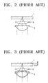
- a conventional aberration correcting apparatus includes an objective lens 3 for focusing an incident beam and a condensing lens 5 for further condensing the beam focused by the objective lens 3 to form a light spot on an optical disc 1.
- the distance between the condensing lens 5 and the objective lens 3 is adjusted according to thickness variations ( ⁇ d) of the optical disc substrate 1 and wavelength variations of light used, such that aberration can be corrected.
- an aim of embodiments of the present invention to provide an optical pickup for high-density recording/reproduction adopting a single objective lens, in which chromatic aberration caused by different wavelengths of light and/or spherical aberration due to thickness variations of optical discs can be corrected with improved configuration, and thus it is compatible for optical discs having different formats.
- an optical pickup compatible for optical discs having different formats comprising: a first light source for emitting a beam having a relatively short wavelength suitable for a first optical disc with a format; a second light source for emitting a beam having a relatively long wavelength suitable for a second optical disc with another format; an objective lens designed to be suitable for the first optical disc and the wavelength of beam emitted from the first light source, for focusing an incident beam to form a light spot on a corresponding optical disc; a first optical path changing means arranged on the optical path between the first light source and the objective lens, for altering the traveling path of the beam emitted from the first light source; a second optical path changing means arranged on the optical path between the second light source and the objective lens, for altering the traveling path of the beam emitted from the second light source; a third optical path changing means arranged on the optical path between the first optical path changing means and the objective lens, and between the second optical path changing means and the objective lens, for transmitting
- the first light source emits blue light and the second light source emits red light.
- the first light splitting means is a holographic optical element (HOE) for causing a predetermined amount of spherical aberration only to the second beam, such that the second beams further includes spherical aberration relative to the first beam.
- the second signal processing unit may further comprise a delay between the output end of the first and/or second light receiving portions and at least one input end of the second processing unit, for delaying one of the signals output from the first and second light receiving portions to match the phases of the electrical signals.
- the first light splitting means is a polarization holographic optical element (HOE) for generating a first beam having one polarized component and a second beam having the other polarized component, and causing a predetermined amount of spherical aberration only to the second beam having the other polarized component, such that the second beam further includes spherical aberration relative to the first beam; and the optical pickup further comprises a polarization beam splitter disposed on the optical path between the second optical path changing means and the second photodetector, for transmitting or reflecting the first and second beams reflected from a corresponding optical disc and passed through the objective lens, the third optical path changing means and then the second optical path changing means, according to their polarization, wherein the first and second light receiving portions of the second photodetector are arranged such that they are able to separately receive the first and second beams having different polarized components split by the polarization beam splitter.
- HOE polarization holographic optical element
- the optical pickup may of any of claims 1 through 5, further comprise a second light splitting means on the first optical path between the first light source and the optical path changing means, for splitting the beam emitted from the first light source into third and fourth beams to be focused as a main light spot and a sub-light spot on a corresponding optical disc, respectively, wherein the first photodetector includes third and fourth light receiving portions for receiving the third and fourth beams reflected from a corresponding optical disc and passed through the objective lens, the third optical path changing means and then the first optical path changing means, respectively, and the first signal processing portion outputs a reproduction signal from which spherical aberration caused by thickness deviation of the first optical disc is corrected, from electrical signals photoelectrically converted by the third and fourth light receiving portions after having been received by the same.
- the first photodetector includes third and fourth light receiving portions for receiving the third and fourth beams reflected from a corresponding optical disc and passed through the objective lens, the third optical path changing means and then the first optical path changing means, respectively, and the first signal
- a preferred embodiment of a compatible optical pickup for high-density recording/reproduction includes first and second light sources 11 and 21 for emitting laser beams having different wavelengths, an objective lens 17 for focusing an incident beam to form a light spot on an optical disc 10, first through third optical path changing means 13, 23 and 15 for altering the traveling path of an incident beam, a light splitting means for splitting the beam incident from the second light source 21 so as to form at least two light spots on the optical disc 10, first and second photodetectors 19 and 29 for receiving beams reflecting from the optical disc 10 to detect signals through photoelectric conversion, and first and second signal processing units 20 and 30 for detecting a reproduction signal of the optical disc 10 from the signals detected by the first and second photodetectors 19 and 29.
- the optical disc 10 is a first optical disc or a second optical disc which have different formats.
- the first optical disc may be, for example, future generation digital versatile disc (so-called, high-definition (HD)-DVDs) family media with a substrate thickness of 0.6 mm or less (the thickness from the light incident surface to the information recording surface), and the second optical disc may be, for example, DVD family media (hereinafter, referred to as DVDs) with a substrate thickness of 0.6 mm.
- DVDs DVD family media
- the first light source 11, the first optical path changing means 13, the first photodetector 19 and the first signal processing unit 20 are used for recording an information signal on and/or reproducing an information signal from the first optical disc.
- the first light source 11 emits a relatively short wavelength of light, for example, about 400 nm light, suitable for the first optical disc. Diverging beam emitted from the first light source 11 is collimated by a collimating lens 12.
- the first optical path changing means 13 includes, for example, a beam splitter for transmitting a portion of the incident beam and reflecting the remainder of the incident beam, as shown in Figure 4.
- the beam splitter can be a flat type or prism type beam splitter, other than the cubic type beam splitter shown in Figure 4.
- the first optical path changing means may include a polarization beam splitter (not shown) for transmitting or reflecting the incident beam according to their polarization to alter the traveling path of the incident beam, and a phase retardation plate (not shown) disposed on the optical path between the polarization beam splitter and the third optical path changing means 15 to causing lag in-phase to the incident beam.
- the phase retardation plate is a quarter-wave plate for retarding the phase of the incident beam by ⁇ /4.
- the objective lens 17 is optimized for the substrate thickness of the first optical disc and the wavelength of light emitted from the first light source 11, and has an NA of 0.6 or more. For this reason, when light emitted from the second light source 21 is focused on the optical disc 10 by the objective lens 177, chromatic aberration occurs due to a difference in wavelengths of the beams from the first and second light sources 11 and 21. In addition, when the substrate thickness of the first optical disc is different from that of the second optical disc, which will be described later, spherical aberration occurs in the light spot focused on the second optical disc after having been emitted form the second light source 2, due to a difference in substrate thicknesses.
- the chromatic aberration and/or spherical aberration are corrected by the light splitting means, the second photodetector 29 and the second signal processing unit 30, which will be described later, and thus the optical pickup according to the present invention is compatible for the first and second optical discs.
- the third optical path changing means 15 is disposed on the optical path between the first optical path changing means 13 and the objective lens 17, transmits one of the beams emitted from the first and second light sources 11 and 12, and reflects the other beam, thereby changing the traveling path of the beams emitted from the first and second light sources 11 and 21.
- the third optical path changing means 15 may be a beam splitter with a mirror surface 15a for transmitting the beam emitted from the first light source 11 and reflecting the beam emitted from the second light source 21.
- the mirror surface 15a is coated such that it is able to transmit blue light and reflect red light.
- the first photodetector 19 receives the beam reflected from the first optical disc after having been emitted from the light source 11, through the objective lens 17, the third optical path changing means 15 and the first optical path changing means 13 in succession, and detects signals from the received beam through photoelectric conversion.
- the first signal processing unit 20 detects a reproduction information signal from the first optical disc using the signals detected by the first photodetector.
- the optical pickup is able to record an information signal on a future generation DVD and reproduce a recorded information signal from a future generation DVD.
- the second light source 21, the second optical path changing means 23, the light splitting means, the second photodetector 29 and the second signal processing unit 20 cooperatively record an information signal on and/or reproduce an information signal from the second optical disc.
- the second light source 21 emits a relatively long wavelength of light, for example, about 650 nm light, suitable for the second optical disc. Diverging beam emitted from the second light source 21 is collimated by a collimating lens 22.
- the parallel beam is split into at least two beams including a first beam I and a second beam II by the light splitting means.
- the first and second beams I and II are focused through the objective lens 17 on the optical disc 10, thereby resulting in a main light spot and a sub-light spot.
- the light splitting means may include a holographic optical element (HOE) 25 capable of causing a predetermined amount of spherical aberration to the second beam II, as well as splitting the incident beam into the first and second beams I and II.
- the first beam I is the 0 th order beam diffracted by the HOE 25
- the second beam II is the ⁇ 1 st order beam diffracted by the HOE 25.
- the second optical path changing means 23, which is arranged on the optical path between the HOE 25 and the third optical path changing means 15, alters the traveling path of the incident beam.
- light incident from the second light source 21 is directed toward the third optical path changing means 15 by the second optical path changing means 23, and light incident from the third optical path changing means 15 is directed toward the second photodetector 19 by the second optical path changing means 23.
- the second optical path changing means 23 may be a beam splitter, or a combination of a polarization beam splitter (PBS) and a phase retardation plate.
- PBS polarization beam splitter
- the first and second beams I and II from the HOE 25 pass through the second and third optical path changing means 23 and 15 in sequence, and focused by the objective lens 17 on the same track of the optical disc 10 as a main light spot and a sub-light spot.
- the main light spot and the sub-light spot on the optical disc 10 include chromatic aberration caused by a difference in wavelengths of light emitted from the first and second light sources 11 and 21.
- the main light spot and the sub-light spot also include spherical aberration caused by a difference in substrate thicknesses.
- the sub-light spot further includes spherical aberration intentionally caused by the HOE 25.
- the first and second beams I and II are received by the second photodetector 29 through the objective lens 17, the third optical path changing means 15, the second optical path changing means 23, and a condensing lens 28.
- the condensing lens 28 condenses the first and second beams I and II passed through the second optical path changing means 23.
- the second photodetector 29 includes first and second light receiving portions 29a and 29b for receiving the first and second beams I and II, respectively.
- the second signal processing unit 30 corrects for chromatic aberration and/or spherical aberration due to thickness difference, which are described previously, from the electrical signals obtained through photoelectric conversion by the first and second light receiving portions 29a and 29b, and outputs a reproduction signal.
- the second signal processing unit 30 includes a differential unit 33 for subtracting the signals output from the first and second receiving portions 29a and 29b, a gain controller 35 for amplifying a subtraction signal output from the differential unit 33 with a gain factor k, and an adder 37 for summing a signal output from the gain controller 33 and the signal output from the first receiving portion 29a.
- the second signal processing unit 30 processes the detection signals output from the first and second light receiving portions 29a and 29b using formula (3) below, and outputs a reproduction signal S from which chromatic aberration and spherical aberration due to thickness difference have been corrected:
- S S m + k ( S m - S sub )
- S m represents a main reproduction signal that originates from the main light spot, which has been received and converted into an electrical signal by the first light receiving portion 29a
- S sub represents a sub-reproduction signal that originates from the sub-light spot, which has been received and converted into an electrical signal by the second light receiving portion 29b
- k is a gain factor.
- the gain factor k varies according to the degree of the thickness difference between the first and second optical discs, and is controlled by a k-value adjusting circuit (not shown) such that jitter of the reproduction signal from the second optical disc is minimized.
- the k-value adjusting circuit monitors jittering of the reproduction signal output from the second signal processing unit 30, adjusts the gain factor k according to the monitoring result, and feeds back the result to the gain controller 35 for gain control.
- the second signal processing unit 30 further comprises a delay 31, as shown in Figure 4, for compensating for a time delay between the signals originating from the two light spots.
- the delay 31 is installed between the output end of the second light receiving portion 29a and an input end of the differential unit 33. The delay 31 delays the phase of the preceding signal, for example, output from the second light receiving portion 29a to match the phases of the signals output from the first and second light receiving portions 29a and 29b.
- the first light source 11 operates to emit blue light. Diverging beam emitted from the first light source 11 is collimated by the collimating lens 12, passes through the first and third optical path changing means 13 and 15 in succession, and incident on the objective lens 17.
- the objective lens 17 focuses the incident beam to form a light spot on the recording surface of the optical disc with the first format. For example, if the optical disc with the first format is recordable, an information signal can be recorded by the light spot focused on the recording surface.
- Light reflected from the optical disc with the first format is incident on the first optical path changing means 13 through the objective lens 17 and the third optical path changing means 13 in succession.
- the incident beam is reflected by the first optical path changing means 13, condensed by the condensing lens 18 and received by the first photodetector 19.
- an electrical signal detected by the first photodetector 19 is provided to the first signal processing unit 20, and the first signal processing unit 20 outputs an information signal reproduced from the optical disc with the first format.
- the detection signals of the first photodetector 19 are used in detecting focusing and tracking error signals such that the objective lens 17 scans along the track center of the optical disc in a normal focus position.
- the second light source 21 is operated to emit red light. Diverging beam emitted from the second light source 21 is collimated by the collimating lens 22 and diffracted by the HOE 25 to slit into a first beam I, and a second beam II including spherical aberration.
- the first and second beams I and II transmits the second optical path changing means 23, reflected by the third optical path changing means 15 and incident on the objective lens 17.
- the objective lens 17 focuses the incident first and second beams I and II to form a main light spot and a sub-light spot on the same track of the recording surface of the optical disc with the second format. If the optical disc with the second format is recordable, an information signal can be recorded by the main light spot focused on the recording surface.
- electrical signals detected by the first and second light receiving portions 29a and 29b are input to the second signal processing unit 30, and the second signal processing unit 30 outputs an information signal reproduced from the optical disc with the second format, from which chromatic aberration and/or spherical aberration caused by thickness difference of optical discs described previously are removed.
- the detection signals of the second photodetector 29 can be used in detecting focusing and tracking error signals such that the objective lens 17 scans along the track center of the optical disc in a normal focus position.
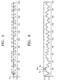
- Figure 5 illustrates a part of a DVD having three pit streams with 0.74 ⁇ m track pitch and 0.40 ⁇ m minimum mark length
- Figure 6 illustrates a signal reproduced from the central track of the optical disc of Figure 5.
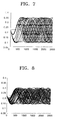
- dashed lines indicated by S o indicate a reproduction signal from the central track of the DVD shown in Figure 5, which is reproduced with a light source having 650 nm wavelength, and an objective lens designed to be suitable for 0.6-mm thick disc substrate with a NA of 0.6.
- the value of jittering of the reproduction signal S o is 8.64%
- the eye-pattern of the signal S o is shown in Figure 7.
- solid lines indicated by S m indicate a reproduction signal from the central track of the DVD shown in Figure 5, which is reproduced with a light source having 400 nm wavelength and an objective lens designed to be suitable for 0.55-mm thick disc substrate.
- the value of jittering of the reproduction signal is 24.16%, and the eye-pattern of the signal S m is shown in Figure 8.
- Dashed lines indicated by S sub indicates a reproduction signal from the DVD of Figure 5 when a second beam II to which spherical aberration corresponding to a substrate thickness of 50 ⁇ m is caused by adopting the HOE 25 is further focused as an sub-light spot on the recording surface.
- the value of jittering of the reproduction signal S sub is 30% or more, and the eye-pattern of the signal S sub is shown in Figure 9.
- Figure 10 illustrates a reproduction signal S obtained by correcting for aberration of the signals S m and S sub using formula (3) above with a gain factor k of 3.5, which is set by the gain adjustor 35 of the second signal processing unit 30 of Figure 4, i.e., S m + 3.5 (S m -S sub ), and then whose DC and AC components are adjusted to be the same as those of the reproduction signal S o .
- the reproduction signal S and S o are almost the same.
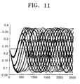
- the reproduction signal S has the eye-pattern shown in Figure 11, and the value of jittering of the reproduction signal is 8.88%, which is similar to the jittering (8.64%) of the signal S o reproduced with a light source having 650 nm wavelength and an objective lens for DVDs.
- the optical pickup according to the present invention can output a reproduction signal from which chromatic aberration and/or spherical aberration caused by thickness difference of disc substrates are removed by the operation using formula (3).
- Figure 12 illustrates the optical arrangement of another preferred embodiment of an optical pickup according to the present invention.
- the optical pickup includes first and second light sources 11 and 21 for emitting beams having different wavelengths, an objective lens 17 for focusing an incident beam to form a light spot on an optical disc 10, first, second and third optical path changing means 13, 53 and 15, a light splitting means for splitting the incident beam emitted from the second light source 21 to form at least two light spots on the optical disc 10, first and second photodetectors 19 and 59 for receiving the beam reflected from the optical disc, and first and second signal processing units 20 and 60 for detecting reproduction signals from electrical signals detected by the first and second photodetectors 19 and 59, respectively.
- the same elements as those illustrated in Figure 4 are represented by the same reference numerals, and description thereof is not provided here.
- the second light source 21, the second light path changing means 53, the light splitting means, the second photodetector 59 and the second signal processing unit 60 are used to record an information signal on and/or reproduce an information signal from a DVD family optical disc with a second format.
- Light collimated by the collimating lens 22 after having been emitted from the second light source 21 is split into at least two beams, first and second beams I' and II' by the light splitting means.
- the first and second beams I' and II' are focused on the optical disc 10 by the objective lens 17 to form a main light spot and a sub-light spot, respectively.
- the light splitting means may be a polarization HOE 55 for generating a first beam I' having one polarized component, for example, P-polarized component, and a second beam II' having the other polarized component, for example, S-polarized component.
- the polarization HOE 55 causes a predetermined amount of spherical aberration only to the S-polarized second beam II'.
- the first and second beams I' and II' are 0 th -order and 1 st -order beams, respectively, diffracted from the polarization HOE 55.
- the second path changing means 53 arranged on the optical path between the polarization HOE 55 and the third optical path changing means 15 alters the optical path of the incident beam.
- the second optical path changing means 53 may be a beam splitter.
- the beam splitter transmits the incident beam from the second light source 21 regardless of their polarization, such that it heads toward the third optical path changing means 15.
- the beam splitter reflects the incident beam from the third optical path changing means 15 regardless of their polarization, such that it heads toward the second photodetector 59.
- the first and second beams I' and II' split by the polarization HOE 55 are focused on the optical disc 10 by the objective lens 17.
- a main light spot from the first beam I' and the sub-light spot from the second beam II' are formed on the same track of the optical disc 10.
- the second signal processing unit 60 does not need a delay, unlike the second signal processing unit 30 (see Figure 4) of the previous embodiment.
- the main light spot and the sub-light spot have similar characteristics to those of the main light spot and the sub-light spot described in the previous embodiment, except that they have different polarized components.
- the optical pickup of Figure 12 may further comprise a polarization beam splitter 58 on the optical path between the second light path changing means 53 and the second light photodetector 59, for splitting the first and second beams I' and II' passed through the objective lens 17, the third and second optical path changing means 15 and 53 in sequence after having been reflected from the optical disc 10 and passed through the objective lens 17, according their polarization, such that they head toward first and second light receiving portions 59a and 59b of the second photodetector 59.
- a polarization beam splitter 58 on the optical path between the second light path changing means 53 and the second light photodetector 59, for splitting the first and second beams I' and II' passed through the objective lens 17, the third and second optical path changing means 15 and 53 in sequence after having been reflected from the optical disc 10 and passed through the objective lens 17, according their polarization, such that they head toward first and second light receiving portions 59a and 59b of the second photodetector 59.
- first and second light receiving portions 59a and 59b of the second photodetector 59 are arranged, such that they are able to separately receive the first and second beams I' and II' split by the polarization beam splitter 58.
- the second signal processing unit 60 processes the electrical signals undergone photoelectric conversion after having been received by the first and second light receiving portions 59a and 59b, using formula (3) above, as in the previous embodiment, so that it outputs a reproduction signal from which chromatic aberration and/or spherical aberration caused by difference in substrate thickness of optical disc are corrected.
- the second signal processing unit 60 has the same structure as that of the second signal processing unit 30 of Figure 4, except that a delay is not included in the second signal processing unit 60 of the present embodiment. For this reason, the constituent elements of the second signal processing unit 60 are designated with the same reference numerals used as in Figure 4, and description of the elements is not provided here.
- the optical system for recording information on or reproducing information from a future generation DVD family optical disc with a first format can be constituted to be the same as or similar to the optical system adopted to record information on or reproduce information from a DVD family optical disc with a second format, described previously with reference to Figures 4 and 12.
- a light splitting means (not shown) is provided between the first light source 11 and the first optical path changing means 13 to split an incident beam such that a main light spot, and a sub-light spot including spherical aberration, are focused on the optical disc with the first format.
- two beams reflected from the optical disc with the first format are received by different light receiving portions (not shown) of the first photodetector 19, respectively, and the first signal processing unit 20 receives and processes electrical signals detected by the first photodetector 19 using formula (3) above, thereby outputting a reproduction signal from which spherical aberration caused by thickness deviation of future generation DVD family optical discs is corrected.
- the spherical aberration can be removed by adjusting a gain factor k in the first signal processing unit 20 for the operation using formula (3) above.
- the optical pickup for high-density recording/reproduction has a configuration in which a sub-light spot including spherical aberration is focused on an optical disc along with a main light spot, and a reproduction signal is detected by processing the two beams reflected from the optical disc and received by a photodetector, using formula (3).
- the inventive optical pickup is compatible for optical discs having different formats, for example, for future generation DVDs and DVDs.
Landscapes
- Physics & Mathematics (AREA)
- Optics & Photonics (AREA)
- Engineering & Computer Science (AREA)
- Signal Processing (AREA)
- Optical Head (AREA)
- Polarising Elements (AREA)
- Diffracting Gratings Or Hologram Optical Elements (AREA)
Applications Claiming Priority (2)
| Application Number | Priority Date | Filing Date | Title |
|---|---|---|---|
| KR2000010875 | 2000-03-04 | ||
| KR1020000010875A KR100694029B1 (ko) | 2000-03-04 | 2000-03-04 | 고밀도 기록/재생용 호환형 광픽업장치 |
Publications (3)
| Publication Number | Publication Date |
|---|---|
| EP1130581A2 true EP1130581A2 (fr) | 2001-09-05 |
| EP1130581A3 EP1130581A3 (fr) | 2003-04-02 |
| EP1130581B1 EP1130581B1 (fr) | 2005-03-16 |
Family
ID=19652263
Family Applications (1)
| Application Number | Title | Priority Date | Filing Date |
|---|---|---|---|
| EP01300155A Expired - Lifetime EP1130581B1 (fr) | 2000-03-04 | 2001-01-09 | Dispositif de lecture/écriture optique à haute densité |
Country Status (7)
| Country | Link |
|---|---|
| US (1) | US6563780B2 (fr) |
| EP (1) | EP1130581B1 (fr) |
| JP (1) | JP4302902B2 (fr) |
| KR (1) | KR100694029B1 (fr) |
| CN (1) | CN1194343C (fr) |
| DE (1) | DE60109336T2 (fr) |
| TW (1) | TW513717B (fr) |
Cited By (4)
| Publication number | Priority date | Publication date | Assignee | Title |
|---|---|---|---|---|
| EP1318507A3 (fr) * | 2001-12-07 | 2006-03-08 | Matsushita Electric Industrial Co., Ltd. | Appareil de traitement d'information optique et méthode de traitement d'information optique |
| EP1684276A1 (fr) * | 2005-01-20 | 2006-07-26 | Samsung Electronics Co., Ltd. | Appareil de capture optique |
| EP1223576A3 (fr) * | 2000-12-28 | 2007-05-30 | Samsung Electronics Co., Ltd. | Tête de lecture optique capable de détecter la variation d'épaisseur d'un support d'enregistrement, et/ou capable de corriger l'aberration sphérique causée par la variation d'épaisseur d'un support d'enregistrement |
| US7345820B2 (en) | 2004-11-11 | 2008-03-18 | Samsung Electronics Co., Ltd. | Optical pick-up apparatus |
Families Citing this family (12)
| Publication number | Priority date | Publication date | Assignee | Title |
|---|---|---|---|---|
| JP3672020B2 (ja) * | 2000-12-18 | 2005-07-13 | 日本電気株式会社 | 光ヘッド装置及び光学式情報記録再生装置 |
| US7061853B2 (en) * | 2001-12-18 | 2006-06-13 | Discovision Associates | High-density optical pickup for rotating media |
| JP3518684B2 (ja) * | 2002-01-11 | 2004-04-12 | 日立マクセル株式会社 | 対物レンズの設計方法、対物レンズ、対物レンズの製造方法、多波長用光学系、光ヘッド及び光デイスク装置 |
| AU2003248344A1 (en) * | 2002-02-26 | 2003-09-09 | Matsushita Electric Industrial Co., Ltd. | Optical element and optical head device using it, and optical information device using this optical head device, and computer, optical disk player, car navigation system, optical disk recorder and optical disk server using this optical information device |
| US7292324B2 (en) * | 2002-10-23 | 2007-11-06 | Koninklijke Philips Electronics N.V. | Spherical aberration detection |
| KR100546351B1 (ko) * | 2003-07-25 | 2006-01-26 | 삼성전자주식회사 | 호환형 광픽업 및 이를 채용한 광 기록 및/또는 재생기기 |
| JP3989889B2 (ja) * | 2003-09-19 | 2007-10-10 | 株式会社リコー | 収差調整装置、光ピックアップ、プログラム、及び記憶媒体 |
| JPWO2005091279A1 (ja) * | 2004-03-19 | 2008-02-07 | コニカミノルタオプト株式会社 | 光ピックアップ装置用の対物光学系、光ピックアップ装置及び光情報記録再生装置 |
| JP2006179127A (ja) * | 2004-12-22 | 2006-07-06 | Toshiba Corp | 光ディスク装置及びその制御方法 |
| US7626152B2 (en) * | 2006-08-16 | 2009-12-01 | Raytheon Company | Beam director and control system for a high energy laser within a conformal window |
| CN102246233B (zh) * | 2008-12-17 | 2015-01-28 | 柯尼卡美能达精密光学株式会社 | 物镜光学元件及光拾取装置 |
| CN102661853B (zh) * | 2012-05-08 | 2014-03-26 | 北京理工大学 | 共焦系统球差测量方法 |
Family Cites Families (5)
| Publication number | Priority date | Publication date | Assignee | Title |
|---|---|---|---|---|
| JPH09251662A (ja) * | 1996-03-15 | 1997-09-22 | Sony Corp | 記録媒体記録再生装置および記録媒体記録再生方法 |
| JP3823425B2 (ja) * | 1997-03-27 | 2006-09-20 | コニカミノルタホールディングス株式会社 | 光ピックアップ装置および光ピックアップ装置の補正素子 |
| JPH10334504A (ja) * | 1997-05-29 | 1998-12-18 | Nec Corp | 光ヘッド装置 |
| KR100514323B1 (ko) * | 1997-12-05 | 2005-12-08 | 삼성전자주식회사 | 복수의광디스크를호환하는대물렌즈를구비한광픽업 |
| JPH11306579A (ja) * | 1998-04-15 | 1999-11-05 | Sony Corp | ビームスプリッタ及び光ピックアップ装置 |
-
2000
- 2000-03-04 KR KR1020000010875A patent/KR100694029B1/ko not_active Expired - Fee Related
-
2001
- 2001-01-09 EP EP01300155A patent/EP1130581B1/fr not_active Expired - Lifetime
- 2001-01-09 DE DE60109336T patent/DE60109336T2/de not_active Expired - Lifetime
- 2001-01-12 CN CNB011016132A patent/CN1194343C/zh not_active Expired - Fee Related
- 2001-01-31 TW TW090101971A patent/TW513717B/zh not_active IP Right Cessation
- 2001-02-27 US US09/793,718 patent/US6563780B2/en not_active Expired - Lifetime
- 2001-03-01 JP JP2001057364A patent/JP4302902B2/ja not_active Expired - Fee Related
Cited By (6)
| Publication number | Priority date | Publication date | Assignee | Title |
|---|---|---|---|---|
| EP1223576A3 (fr) * | 2000-12-28 | 2007-05-30 | Samsung Electronics Co., Ltd. | Tête de lecture optique capable de détecter la variation d'épaisseur d'un support d'enregistrement, et/ou capable de corriger l'aberration sphérique causée par la variation d'épaisseur d'un support d'enregistrement |
| EP1318507A3 (fr) * | 2001-12-07 | 2006-03-08 | Matsushita Electric Industrial Co., Ltd. | Appareil de traitement d'information optique et méthode de traitement d'information optique |
| US7277365B2 (en) | 2001-12-07 | 2007-10-02 | Matsushita Electric Industrial Co., Ltd. | Optical information processing apparatus and method of processing optical information |
| US7345820B2 (en) | 2004-11-11 | 2008-03-18 | Samsung Electronics Co., Ltd. | Optical pick-up apparatus |
| EP1684276A1 (fr) * | 2005-01-20 | 2006-07-26 | Samsung Electronics Co., Ltd. | Appareil de capture optique |
| US7613095B2 (en) | 2005-01-20 | 2009-11-03 | Samsung Electronics Co., Ltd. | Optical pickup apparatus |
Also Published As
| Publication number | Publication date |
|---|---|
| DE60109336T2 (de) | 2005-08-04 |
| JP4302902B2 (ja) | 2009-07-29 |
| DE60109336D1 (de) | 2005-04-21 |
| KR20010086901A (ko) | 2001-09-15 |
| JP2001291270A (ja) | 2001-10-19 |
| KR100694029B1 (ko) | 2007-03-12 |
| CN1311508A (zh) | 2001-09-05 |
| EP1130581B1 (fr) | 2005-03-16 |
| CN1194343C (zh) | 2005-03-23 |
| US20010036141A1 (en) | 2001-11-01 |
| TW513717B (en) | 2002-12-11 |
| EP1130581A3 (fr) | 2003-04-02 |
| US6563780B2 (en) | 2003-05-13 |
Similar Documents
| Publication | Publication Date | Title |
|---|---|---|
| EP1130581B1 (fr) | Dispositif de lecture/écriture optique à haute densité | |
| JP3553458B2 (ja) | 互換型光ピックアップ装置 | |
| EP1156483A2 (fr) | Lecteur de disque optique compatible et procédé d'enregistrement et de reproduction de données | |
| US20080049581A1 (en) | Optical pick-up | |
| JP2559011B2 (ja) | 光ヘッド | |
| JP2005327403A (ja) | 光ピックアップ及び光学記録媒体記録再生装置 | |
| JP2010519671A (ja) | 互換型光ピックアップ及びこれを採用した光情報記録媒体システム | |
| CN1273414A (zh) | 光学拾取器 | |
| US20080049586A1 (en) | Optical pickup apparatus and optical information recording/reproducing apparatus | |
| CN101136220B (zh) | 光拾取装置 | |
| US20040246876A1 (en) | Optical pickup apparatus comprising optical device with phase shift coating layer | |
| JP2001195772A (ja) | 光ピックアップ装置 | |
| JPH10241196A (ja) | 偏光光分割器を使用するcd−r/dvd用光記録/ピックアップヘッド | |
| US7990833B2 (en) | Optical pickup device with diffraction patterns on object lens | |
| JP3670091B2 (ja) | 光ピックアップ | |
| JP3455675B2 (ja) | 光ピックアップ装置 | |
| JP2000090471A (ja) | 光ピックアップ装置 | |
| US7719949B2 (en) | Optical head | |
| JP2005353259A (ja) | 光ピックアップ、光ディスク装置及び光学倍率調整方法 | |
| JP2003317308A (ja) | 光学ヘッド及び光ディスク装置 | |
| JP4380055B2 (ja) | 光ヘッド、光検出素子、及び光記録媒体記録再生装置 | |
| JPH0944887A (ja) | 光ピックアップ及び再生装置 | |
| JP2007220175A (ja) | 光ピックアップ装置 | |
| JP2002269795A (ja) | 光ピックアップ及びそれを用いた光学的情報再生装置 | |
| US20070025229A1 (en) | Optical pickup apparatus |
Legal Events
| Date | Code | Title | Description |
|---|---|---|---|
| PUAI | Public reference made under article 153(3) epc to a published international application that has entered the european phase |
Free format text: ORIGINAL CODE: 0009012 |
|
| 17P | Request for examination filed |
Effective date: 20010123 |
|
| AK | Designated contracting states |
Kind code of ref document: A2 Designated state(s): AT BE CH CY DE DK ES FI FR GB GR IE IT LI LU MC NL PT SE TR |
|
| AX | Request for extension of the european patent |
Free format text: AL;LT;LV;MK;RO;SI |
|
| PUAL | Search report despatched |
Free format text: ORIGINAL CODE: 0009013 |
|
| AK | Designated contracting states |
Designated state(s): AT BE CH CY DE DK ES FI FR GB GR IE IT LI LU MC NL PT SE TR Kind code of ref document: A3 Designated state(s): AT BE CH CY DE DK ES FI FR GB GR IE IT LI LU MC NL PT SE TR |
|
| AX | Request for extension of the european patent |
Extension state: AL LT LV MK RO SI |
|
| RIC1 | Information provided on ipc code assigned before grant |
Ipc: 7G 11B 7/125 B Ipc: 7G 11B 7/135 B Ipc: 7G 11B 7/00 B Ipc: 7G 11B 7/12 A |
|
| 17Q | First examination report despatched |
Effective date: 20030718 |
|
| AKX | Designation fees paid |
Designated state(s): DE FR GB NL |
|
| GRAP | Despatch of communication of intention to grant a patent |
Free format text: ORIGINAL CODE: EPIDOSNIGR1 |
|
| GRAS | Grant fee paid |
Free format text: ORIGINAL CODE: EPIDOSNIGR3 |
|
| GRAA | (expected) grant |
Free format text: ORIGINAL CODE: 0009210 |
|
| AK | Designated contracting states |
Kind code of ref document: B1 Designated state(s): DE FR GB NL |
|
| REG | Reference to a national code |
Ref country code: GB Ref legal event code: FG4D |
|
| REG | Reference to a national code |
Ref country code: IE Ref legal event code: FG4D |
|
| REF | Corresponds to: |
Ref document number: 60109336 Country of ref document: DE Date of ref document: 20050421 Kind code of ref document: P |
|
| PLBE | No opposition filed within time limit |
Free format text: ORIGINAL CODE: 0009261 |
|
| STAA | Information on the status of an ep patent application or granted ep patent |
Free format text: STATUS: NO OPPOSITION FILED WITHIN TIME LIMIT |
|
| ET | Fr: translation filed | ||
| 26N | No opposition filed |
Effective date: 20051219 |
|
| REG | Reference to a national code |
Ref country code: FR Ref legal event code: PLFP Year of fee payment: 16 |
|
| PGFP | Annual fee paid to national office [announced via postgrant information from national office to epo] |
Ref country code: GB Payment date: 20151222 Year of fee payment: 16 |
|
| PGFP | Annual fee paid to national office [announced via postgrant information from national office to epo] |
Ref country code: NL Payment date: 20151223 Year of fee payment: 16 Ref country code: FR Payment date: 20151229 Year of fee payment: 16 |
|
| PGFP | Annual fee paid to national office [announced via postgrant information from national office to epo] |
Ref country code: DE Payment date: 20151223 Year of fee payment: 16 |
|
| REG | Reference to a national code |
Ref country code: DE Ref legal event code: R119 Ref document number: 60109336 Country of ref document: DE |
|
| REG | Reference to a national code |
Ref country code: NL Ref legal event code: MM Effective date: 20170201 |
|
| GBPC | Gb: european patent ceased through non-payment of renewal fee |
Effective date: 20170109 |
|
| REG | Reference to a national code |
Ref country code: FR Ref legal event code: ST Effective date: 20170929 |
|
| PG25 | Lapsed in a contracting state [announced via postgrant information from national office to epo] |
Ref country code: FR Free format text: LAPSE BECAUSE OF NON-PAYMENT OF DUE FEES Effective date: 20170131 |
|
| PG25 | Lapsed in a contracting state [announced via postgrant information from national office to epo] |
Ref country code: DE Free format text: LAPSE BECAUSE OF NON-PAYMENT OF DUE FEES Effective date: 20170801 Ref country code: NL Free format text: LAPSE BECAUSE OF NON-PAYMENT OF DUE FEES Effective date: 20170201 Ref country code: GB Free format text: LAPSE BECAUSE OF NON-PAYMENT OF DUE FEES Effective date: 20170109 |