EP1130745A2 - Bürstenloser Motor - Google Patents
Bürstenloser Motor Download PDFInfo
- Publication number
- EP1130745A2 EP1130745A2 EP01103091A EP01103091A EP1130745A2 EP 1130745 A2 EP1130745 A2 EP 1130745A2 EP 01103091 A EP01103091 A EP 01103091A EP 01103091 A EP01103091 A EP 01103091A EP 1130745 A2 EP1130745 A2 EP 1130745A2
- Authority
- EP
- European Patent Office
- Prior art keywords
- case
- brushless motor
- circuit
- switching
- stator
- Prior art date
- Legal status (The legal status is an assumption and is not a legal conclusion. Google has not performed a legal analysis and makes no representation as to the accuracy of the status listed.)
- Withdrawn
Links
Images









Classifications
-
- H—ELECTRICITY
- H02—GENERATION; CONVERSION OR DISTRIBUTION OF ELECTRIC POWER
- H02K—DYNAMO-ELECTRIC MACHINES
- H02K3/00—Details of windings
- H02K3/46—Fastening of windings on the stator or rotor structure
- H02K3/50—Fastening of winding heads, equalising connectors, or connections thereto
-
- H—ELECTRICITY
- H02—GENERATION; CONVERSION OR DISTRIBUTION OF ELECTRIC POWER
- H02K—DYNAMO-ELECTRIC MACHINES
- H02K11/00—Structural association of dynamo-electric machines with electric components or with devices for shielding, monitoring or protection
- H02K11/30—Structural association with control circuits or drive circuits
- H02K11/33—Drive circuits, e.g. power electronics
-
- H—ELECTRICITY
- H02—GENERATION; CONVERSION OR DISTRIBUTION OF ELECTRIC POWER
- H02K—DYNAMO-ELECTRIC MACHINES
- H02K29/00—Motors or generators having non-mechanical commutating devices, e.g. discharge tubes or semiconductor devices
- H02K29/06—Motors or generators having non-mechanical commutating devices, e.g. discharge tubes or semiconductor devices with position sensing devices
- H02K29/08—Motors or generators having non-mechanical commutating devices, e.g. discharge tubes or semiconductor devices with position sensing devices using magnetic effect devices, e.g. Hall-plates, magneto-resistors
-
- H—ELECTRICITY
- H02—GENERATION; CONVERSION OR DISTRIBUTION OF ELECTRIC POWER
- H02K—DYNAMO-ELECTRIC MACHINES
- H02K5/00—Casings; Enclosures; Supports
- H02K5/04—Casings or enclosures characterised by the shape, form or construction thereof
- H02K5/22—Auxiliary parts of casings not covered by groups H02K5/06-H02K5/20, e.g. shaped to form connection boxes or terminal boxes
- H02K5/225—Terminal boxes or connection arrangements
-
- H—ELECTRICITY
- H02—GENERATION; CONVERSION OR DISTRIBUTION OF ELECTRIC POWER
- H02K—DYNAMO-ELECTRIC MACHINES
- H02K5/00—Casings; Enclosures; Supports
- H02K5/24—Casings; Enclosures; Supports specially adapted for suppression or reduction of noise or vibrations
-
- H—ELECTRICITY
- H02—GENERATION; CONVERSION OR DISTRIBUTION OF ELECTRIC POWER
- H02K—DYNAMO-ELECTRIC MACHINES
- H02K2211/00—Specific aspects not provided for in the other groups of this subclass relating to measuring or protective devices or electric components
- H02K2211/03—Machines characterised by circuit boards, e.g. pcb
-
- H—ELECTRICITY
- H02—GENERATION; CONVERSION OR DISTRIBUTION OF ELECTRIC POWER
- H02K—DYNAMO-ELECTRIC MACHINES
- H02K9/00—Arrangements for cooling or ventilating
- H02K9/02—Arrangements for cooling or ventilating by ambient air flowing through the machine
Definitions
- the present invention relates in general to brushless motors and more particularly to brushless motors of a type which exhibits a satisfied heat proof performance and is easy to be assembled.
- the motor 100 comprises a drive circuit 102 for driving a motor shaft 104.
- the drive circuit 102 generally comprises a filter section which filters out surges from a supplied electric power, a switching section which switches the path of the current from the filter section toward a stator 106 thereby to vary the magnetic fields generated by the stator 106 and a control section which controls rotation of the motor shaft 104 by controlling the switching timing of the switching section.
- These sections of the drive circuit 102 are all arranged on a circuit substrate 108.
- the circuit substrate 108 is accommodated in a circuit protection case 110.
- the switching section comprises a plurality of switching elements 112 which switch the path of current directed to coils 114 of the stator 106, and the control section comprises electronic parts 107 which control the switching timing of the switching elements 112. Since the switching elements 112 produce a considerable heat under operation, these elements 112 are attached a heat sink 115 which is formed with a plurality of heat radiation fins 116. That is, under operation of the motor 100, the heat generated by the switching elements 112 is transmitted to the heat sink 114 and released to the open air from the heat radiation fins 116.
- the motor 200 comprises a drive circuit 202 for driving a motor shaft 204.
- the drive circuit 202 is accommodated in a circuit protection case 210.
- the drive circuit 202 is printed on a circuit substrate 212, and generally comprises a filter section 202a which filters our surges from a supplied power, and a control section 202b which controls magnetic fields of a stator 214 by switching the path of the current from the filter section 202a at given intervals.
- the control section 202b comprises a plurality of switching elements 216 which switch the path of current directed to coils 214a of the stator 214.
- the switching elements 216 are attached to a heat sink 218 formed with a plurality of heat radiation fins 218a. Thus, under operation of the motor 200, the heat generated by the switching elements 216 is transmitted to the heat sink 218 and released to the open air from the heat radiation fins 218a.
- the coils 214a of the stator 214 and the control section 202b of the drive circuit 202 are connected through terminal pins 220 which extend from the coils 214a, joint bars 222 held by the circuit substrate 212 and bus bars 224 which connect the joint bars 222 and the terminal pins 220.
- a brushless motor which is constructed to suppress or at least minimize undesired heat transmission from a heat generating switching section of a drive circuit to a control section of the same.
- a brushless motor which comprises a circuit protecting case; a holder disposed on the case; a motor shaft rotatably held by the holder; a stator disposed about the holder, the stator including a plurality of coils which surround the motor shaft; a yoke fixed to the motor shaft to rotate therewith, the yoke covering the stator with a given space therebetween; permanent magnets held by the yoke; a circuit substrate tightly held in the circuit protecting case; a drive circuit arranged on the circuit substrate, the drive circuit including a switching section which switches the path of current directed to the coils of the stator and a control section which controls a switching timing of the switching section, the switching section including a plurality of switching elements which generate a certain heat when operated; and a partition wall provided in the circuit protection case to partition the interior of the case into a first chamber to which the switching elements of the switching section are exposed and a second chamber to which the control section is exposed.
- a brushless motor 1A which is a first embodiment of the present invention.
- the brushless motor 1A is suitable for driving a blower fan (not shown) used in an automotive air conditioner.
- the brushless motor 1A comprises a motor shaft 2 to which the blower fan is connected.
- the motor shaft 2 is rotatably held in a cylindrical holder 4 through a pair of bearings 3.
- the stator 5 comprises a core 5a which includes laminated metal films, a pair of insulating members 5b which are concentrically disposed on the core 5a and a plurality of coils 5c disposed about the insulating members 5b. As shown, the upper insulating member 5b holds the upper side bearing 3.
- stator 5 there are arranged four permanent magnets 6 which are secured to the inner surface of a cut-shaped yoke 7 at evenly spaced intervals.
- the yoke 7 is secured to the motor shaft 2 at its diametrically reduced upper end and thus the yoke 7 and the motor shaft 2 rotate together as a single unit.
- the cylindrical holder 4 has a flange 4a at its lower side, which is secured to a circuit protection case 10 of plastics through a plurality of rubber cushions 8. Each rubber cushion 8 is secured to the case 10 through a bolt (no numeral).
- the circuit protection case 10 generally comprises an upper-half part 11 which has the holder 4 secured thereto and a lower-half part 12 which is detachably connected to the upper-half part 11.
- a sensor magnet 13 which is fixed to a lower end of the motor shaft 2 to rotate therewith and a drive circuit which drives the motor shaft 2.
- the sensor magnet 13 is so constructed and arranged that portions corresponding to the four permanent magnets 6 have the same poles as the permanent magnets 6.
- the drive circuit comprises a filter section 20 which filters out surges from a supplied electric power, a switching section 30 which switches the path of the current from the filter section 20 thereby to vary the magnet fields generated by the stator 5 and a control section 40 which controls rotation of the motor shaft 2 by controlling the switching timing of the switching section 30.
- the filter section 20 is installed in a plastic inner case 21 connected to the upper-half part 11 of the circuit protection case 10 and comprises an electrolytic capacitor 22, a common-mode choke coil 23 and a wiring bus bar 24 (see Fig. 2).
- the switching section 30 and the control section 40 are provided on a common circuit substrate 14.
- the switching section 30 comprises six switching elements 31 which switch the path of current directed to the coils 5c of the stator 5 from the filter section 20.
- the switching circuit 30 is arranged at a left portion of the circuit substrate 14.
- the control section 40 comprises an integrated circuit 41 which controls the switching timing of each switching element 31 and a Hall element (not shown) which detects an angular position of the permanent magnets 6 with the aid of the sensor magnet 13.
- the control section 40 is arranged on a right part of the circuit substrate 14.
- the switching elements 31 are pressed against an aluminum heat sink 32 by means of a spring member 33.
- the heat sink 32 is formed with a plurality of heat radiation fins 32a which are exposed to the open air as shown, From these fins 32a, a marked heat generated by the switching elements 31 and transmitted to the heat sink 32 is released to the outside of the circuit protection case 10, that is, to the open air.
- the heat sink 32 is in the shape of arch and secured to the circuit substrate 14. As shown, the heat radiation fins 32a are exposed to the open air through an opening formed in a front wall part of the upper-half part 11 of the case 10.
- the spring member 33 is fixed to the circuit substrate 14.
- the plastic inner case 21 and the circuit substrate 14 are connected through bolts to bosses which are projected from a rear wall of the upper-half part 11 of the case 10.
- Fig. 2 is a view taken from the direction of the arrow "II" of Fig. 1 with the lower-half part 12 of the case 10 removed.
- a plus terminal 25 which is to be connected to a plus terminal of a battery (not shown), an earth terminal 26 which is to be connected to a body of an associated motor vehicle and a signal terminal 27 which receives signals from an external control equipment.
- the plus terminal 25 and the earth terminal 26 are connected to the filter section 20 of the drive circuit through the wiring bus bar 24.
- Denoted by numeral 28 is a varistor (variable resistor) to which the wiring bus bar 24 is also connected.
- Fig. 3 is a back view of the circuit substrate 14.
- the signal terminal 27 of the inner case 21 is connected to a second part 14b of the circuit substrate 14.
- the switching section 30 of the drive circuit is formed on a first part 14a of the circuit substrate 14.
- the wiring bus bar 24 (see Fig. 2) has terminals which are projected toward the circuit substrate 14 to connect to given portions of the first part 14a. With this, the filter section 20 and the switching section 30 are connected.
- an upper surface of the circuit substrate 14 at a portion corresponding to the boundary part between the first and second parts 14a and 14b has only the wiring pattern 14c covered with an insulating film 14c.
- an insulating film 14c As will become apparent as the description proceeds, to the upper surface of the corresponding portion of the substrate 14, there contacts a lower edge of a first section 81 of a partition wall 80 (see Fig. 1), and to the lower surface of the corresponding portion of the substrate 14, there contacts an upper edge of a second section 82 of the partition wall 80.
- the switching section 30 and the control section 40 are connected through the wiring . pattern 14c of the circuit substrate 14.
- each terminal pin 16 has a projected part held by a seal member 17 of rubber.
- the seal member 17 hermetically seals the passage of upper-half part 11 of the case 10 through which the terminal pin 16 passes.
- the heat sink 32 is electrically connected to a ground pattern of the wiring pattern 14c of the circuit substrate 14.
- the ground pattern is connected to a ground terminal of the connecting bus bars 15 which are connected to the earth terminal 26 (see Fig. 2).
- Fig. 2 to the wiring bus bar 24 connected to the earth terminal 26, there is arranged an after-mentioned clip member 60.
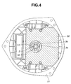
- Fig. 4 is a view similar to Fig. 2, but with the drive circuit and the sensor magnet 13 removed from the drawing. As is seen from Figs. 2 and 4, on an inner surface of the upper-half part 11, there is disposed a rectangular shielding plate 50 of metal.
- the shielding plate 50 functions to shield radio noises emitted from the drive circuit in the circuit protection case 10.
- the shielding plate 50 is made of a resilient metal plate.
- the shielding plate 50 is formed with a circular opening 51 through which the motor shaft 2 passes.
- the circular opening 51 is formed with a smaller rectangular piece 52 projected thereinto.
- the rectangular piece 52 is resiliently engaged with one of projections of a retainer 3a of the lower bearing 3 (see Fig. 1).
- the retainer 3a is made of a metal and holds an impregnated metal member 3b which slidably contacts the motor shaft 2.
- the shielding plate 50 is electrically connected to the motor shaft 2 through the retainer 3a and the impregnated metal member 3b, and electrically connected to the cup-shaped yoke 7 through the motor shaft 2.
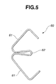
- This clip member 60 is made of a metal plate and comprises a pair of resilient wing portions 61 and a turned-up center portion 62 through which the wing portions 61 are connected.
- the clip member 60 is so arranged that the turned-up center portion 62 thereof is inserted into the wiring bus bar 24 near the earth terminal 26 having one of the resilient wing portions 61 thereof pressed against the shielding plate 50 and the other of the wing portions 61 thereof pressed against a noise shielding plate 70 of metal (see Fig. 1) put on an inner surface of the lower-half part 12 of the case 10.
- the two shielding plates 50 and 70 are electrically connected to the earth terminal 26 through the clip member 60 and the wiring bus bar 24.
- the cup-shaped yoke 7 is electrically connected to the earth terminal 26 through the motor shaft 2, the bearings 3, the shielding plate 50, the clip member 60 and the wiring bus bar 24.
- the detail of the shielding plate 70 will be described hereinafter.
- the partition wall 80 by which the case 10 is divided into a first chamber 10a which contains therein the switching section 30 and a second chamber 10b which contains therein the control section 40.
- the first part 14a of the circuit substrate 14 that constitutes the switching section 30 and the second part 14b of the circuit substrate 14 that constitutes the control section 40 are bounded by the partition wall 80.
- the partition wall 80 comprises the first section 81 which contacts at its leading edge to the upper surface (as viewed in Fig. 1) of the circuit substrate 14 at the boundary part between the first and second parts 14a and 14b, and the second section 82 which contacts at its leading edge to the lower surface (as viewed in Fig. 1) of the circuit substrate 14 at the corresponding boundary part.
- the leading edge of the second section 82 is directed toward the bottom of the lower-half part 12 of the case 10 keeping a certain clearance (or slit) 83 defined therebetween. Accordingly, the first and second chambers 10a and 10b are communicated through the clearance 83.
- the upper-half part 11 of the case 10 is formed near the switching element 31 with a first ventilation opening 11a through which the first chamber 10a is communicated with the open air.
- a grid member is attached to the first ventilation opening 11a for suppressing invasion of foreign things into the case 10.
- the bottom wall 12a of the lower-half part 12 of the case is formed at its center portion with a second ventilation opening 12b through which the second chamber 10b is communicated with the open air.
- Fig. 6 is a plan view of the lower-half part 12 of the case 10, and Fig. 7 is an enlarged sectional view taken along the line VII-VII of Fig. 6.
- the shielding plate 70 is attached to the inner surface of the lower-half part 12 of the case 10.
- the shielding plate 70 is made of a resilient metal plate.
- the second ventilation opening 12b of the lower-half part 12 is formed with an annular projection 12c which passes through a center opening formed in the shielding plate 70.
- the center opening of the shielding plate 70 has circularly arranged resilient pawls 71 which resiliently abut against the annular projection 12c.
- each pawl 12d is formed with a sharply inclined inner surface 12e, so that once the peripheral edges of the shielding plate 70 are pressed into the bottom surface of the lower-half part 12 of the case 10 through the pawls 12d in a so-called snap action manner, the peripheral edges are tightly held in position.
- the shielding plate 70 Due to the resilient abutting of the resilient pawls 71 against the annular projection 12c and the holding of the peripheral edges of the shielding plate 70 by the four pawls 12d, the shielding plate 70 is stably held on the inner surface of the lower-half part 12 of the case 10.
- the partition wall 80 which functions as a heat blocking wall
- the second chamber 10b is protected from being heated by heat generated by the switching elements 31 held in the first chamber 10a.
- the heat sink 32 due to the heat sink 32, the heat generated by the switching elements 31 in the first chamber 10a is effectively released to the open air and the heated air in the first chamber 10a is discharged to the open air through the first ventilation opening 11a. Accordingly, the control section 40 of the drive circuit installed in the second chamber 10b is protected from heat.
- the electric parts 41 for the control section 40 don't need so high heat-proof and thus expensive ones.
- the second ventilation opening 12b formed in the bottom wall of the lower-half part 12 of the case 10, the second chamber 10b, the clearance 83, the first chamber 10a and the first ventilation opening 12a formed in the upper-half part 11 of the case 10 constitute a so-called ventilation passage.
- heated air in the first chamber 10a is discharged to the open air through the first ventilation opening 11a. Due to this air discharging movement, relatively cool air existing near the second ventilation opening 12b is led into the ventilation passage from the opening 12b to travel therethrough and discharged from the first ventilation opening 12a.
- the second and first chambers 10b and 10a of the case 10 are cooled and thus the electric parts including the switching section 30 and the control section 40 installed in the chambers are cooled.
- the shielding metal plate 70 on the inner surface of the lower-half part 12 of the case 10 is cooled.
- the impedance of the plate 70 can be lowered increasing the shielding effect of the same.
- the shielding metal plate 70 is detachably fixed to the inner surface of the lower-half part 12 of the case 10 by means of the four pawls 12d provided by the part 12 and the resilient pawls 71 provided by the plate 70.
- various types of shielding plates can be attached easily to the lower-half part 12 at the need arises.
- the shielding plate 70 fitted to the lower-half part 12, the shielding plate 50 fitted to the upper-half part 11 and the heat sink 32 mounted in the upper-half part 11 are all electrically connected to the earth terminal 26.
- the impedance of the shielding plates 70 and 50 and the heat sink 32 to an earthed body of an associated vehicle can be lowered, and thus noises emitted from the drive circuit in the circuit protecting case 10 can be effectively blocked.
- the cup-shaped yoke 7 covering the stator 5 is electrically connected to the earth terminal 26 through the motor shaft 2, the bearings 3, the shielding plate 50, the clip member 60 and the wiring bus bar 24.
- the impedance of the yoke 7 to the vehicle body can be lowered and thus noises emitted from the coils 5c of the stator 5 can be effectively blocked by the yoke 7.
- each terminal pin 16 is covered with the seal member 17 and thus protected from being rusted due to moisture attached thereto.
- a brushless motor 1B which is a second embodiment of the present invention.
- the brushless motor 1B of the second embodiment is similar in construction to the brushless motor 1A of the first embodiment, the following description will be directed mainly to parts and portions of the second embodiment 1B which are different from those of the first embodiment 1A.
- the sensor magnet 13 which is fixed to the lower end of the motor shaft 2 and a drive circuit 54 which drives the motor 1B.
- the drive circuit 54 comprises a filter section 20 which filters out surges from a supplied power and a control section 61 which controls the magnetic field of the stator 5 by switching the path of current from the filter section 20 to the stator 5.
- Fig. 9 is a plan view of the drive circuit 54.
- the control section 61 of the drive circuit 54 is provided on a circuit substrate 62. That is, on the circuit substrate 62, there are arranged switching elements 31 which switch the path of current directed to the coils 5c of the stator 5 from the filter section 20, an integrated circuit 41 which controls the switching timing of each switching element 31, a Hall element (not shown) which detects the angular position of the permanent magnets 6 with the aid of the sensor magnet 13 and an electrolyte capacitor 22.
- the switching elements 31 are pressed against the aluminum heat sink 32 by means of the spring member 33.
- the spring member 33 is arranged below the switching elements 31 and fixed to the circuit substrate 62.
- the heat sink 32 is integrally formed with a plurality of heat radiation fins 32a.
- the heat sink 32 is secured to the circuit substrate 62.
- the spring member 33 is arranged below the switching elements 31 and fixed to the circuit substrate 62.
- Fig. 10 is a view taken from the direction of the arrow "X" of Fig. 8 with the lower-half part 12 of the case 10 removed.
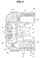
- Fig. 11 is a plan view of the filter section 20.
- the filter section 20 is installed in the plastic inner case 21 fixed to . the upper-half part 11 of the case 10 and comprises the electrolytic capacitor 22, the common-mode choke coil 23, the variable resistor 28 and a fuse 64 (see Fig. 11).
- the inner case 21 is secured through bolts to a projection that extends downward from the upper-half part 11 of the case 10.
- the circuit substrate 62 is fixed to the inner case 21 and arranged above the same.
- a vibration isolation structure As is seen from Figs. 10 and 11, to the inner case 21, there are mounted three connecting bus bars 15.
- the bus bars 15 are connected to the corresponding coils 5c of the stator 5 and welded to the three terminal pins 16.
- Each terminal pin 16 passes through the upper-half part 11 of the case 10 and is connected to the control section 61 (see Fig. 8) of the drive circuit 54.
- a vibration isolation structure Between the stator 5 and the circuit substrate 62 of the control section 61, there is arranged a vibration isolation structure.
- each bus bar 15 passes through an opening 66 formed in the circuit substrate 62 and welded to a given portion of the circuit on the circuit substrate 62.
- the welding of the bus bars 15 to the terminal pins 16 is carried out after the inner case 21 and the circuit substrate 62 are fixed to the upper-half part 11 of the case 10.
- a raised part of a wiring bus bar 68 As is seen from Figs. 10 and 11, to a given portion of the circuit substrate 62, there is welded a raised part of a wiring bus bar 68. With this, the filter section 20 and the control section 61 are electrically connected.
- Fig. 12 there is shown a molded flat unit 67 including the wiring bus bar 68 and the connecting bus bars 15, which is a semi-finished product.
- Fig. 13A shows an earth (or plus) terminal 72 or 73 and
- Fig. 13B shows a signal terminal 74, which are held by the flat unit 67 of Fig. 12.
- the wiring bus bar 68 and the connecting bus bars 15 are united through plastic bridge portions 76. After molding this product 67, the plastic bridge portions 76 are removed and given portions of the bus bars 68 and 15 are bent in desired directions.
- the plus terminal 72, the earth terminal 73 and the signal terminal 74 are welded to given portions of the wiring and connecting bus bars 68 and 15. Upon assembly, the welded portions are embedded in the plastic inner case 21.
- the plus terminal 72 and the signal terminal 74 are connected by the fuse 64.
- the signal terminal 74 is connected to a given portion of the control section 61.
- the signal terminal 74 is plated with gold or other highly conductive antioxidant metal for reliable electric connection with its counterpart (viz., female member).
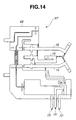
- FIG. 14 there is shown a modification 67' of the above-mentioned molded flat unit 67.
- Figs. 15A, 15B and 15C respectively show earth, signal and plus terminals 72', 74' and 73' which are held by the flat unit 67' of Fig. 14. Similar to the above-mentioned flat unit 67, the earth, signal and plus terminals 72', 73' and 74' are welded to given portions of the wiring and connecting bus bars 68 and 15. Upon assembly, the welded portions are embedded in the plastic inner case 21.
- the connecting bus bars 15 are mounted to the inner case 21 and welding of the terminal pins 16 to the bus bars 15 is carried out after the inner case 21 is fixed to the upper-half part 11 of the case 10. That is, during the welding of the pins 16 to the bus bars 15, the inner case 21 can serve as a positioning tool for the bus bars 15. In case of the conventional brushless motor 200 of Fig. 17, such took is needed.
- each welded portion between the terminal 72, 73 or 74 and the bus bar 68 or 15 is embedded in the plastic inner case 21.
- the welded portion is mechanically reinforced and protected from oxidation.
Landscapes
- Engineering & Computer Science (AREA)
- Power Engineering (AREA)
- Microelectronics & Electronic Packaging (AREA)
- Motor Or Generator Frames (AREA)
- Brushless Motors (AREA)
Applications Claiming Priority (4)
| Application Number | Priority Date | Filing Date | Title |
|---|---|---|---|
| JP2000057285A JP4053709B2 (ja) | 2000-03-02 | 2000-03-02 | ブラシレスモータ |
| JP2000057285 | 2000-03-02 | ||
| JP2000085392A JP4083365B2 (ja) | 2000-03-24 | 2000-03-24 | ブラシレスモータ |
| JP2000085392 | 2000-03-24 |
Publications (2)
| Publication Number | Publication Date |
|---|---|
| EP1130745A2 true EP1130745A2 (de) | 2001-09-05 |
| EP1130745A3 EP1130745A3 (de) | 2003-12-10 |
Family
ID=26586618
Family Applications (1)
| Application Number | Title | Priority Date | Filing Date |
|---|---|---|---|
| EP01103091A Withdrawn EP1130745A3 (de) | 2000-03-02 | 2001-02-09 | Bürstenloser Motor |
Country Status (2)
| Country | Link |
|---|---|
| US (1) | US6617719B2 (de) |
| EP (1) | EP1130745A3 (de) |
Cited By (6)
| Publication number | Priority date | Publication date | Assignee | Title |
|---|---|---|---|---|
| EP1523087A1 (de) * | 2003-10-06 | 2005-04-13 | Ziehl-Abegg AG | Elektromotor mit daran befestigtem Elektronikgehäuse |
| CN102414961A (zh) * | 2009-04-22 | 2012-04-11 | 三菱电机株式会社 | 电动机、电气设备以及电动机的制造方法 |
| WO2014114463A3 (de) * | 2013-01-26 | 2015-08-13 | Brose Fahrzeugteile GmbH & Co. Kommanditgesellschaft, Würzburg | Rotierende elektrische maschine |
| WO2015197574A1 (de) * | 2014-06-26 | 2015-12-30 | Brose Fahrzeugteile GmbH & Co. Kommanditgesellschaft, Würzburg | Elektrische maschine |
| CN106067711A (zh) * | 2015-04-24 | 2016-11-02 | 阿斯莫株式会社 | 车辆用马达驱动控制装置 |
| WO2022043052A1 (de) * | 2020-08-24 | 2022-03-03 | Robert Bosch Gmbh | Elektrische maschine mit einem elektrischen schleifkontakt |
Families Citing this family (30)
| Publication number | Priority date | Publication date | Assignee | Title |
|---|---|---|---|---|
| DE10119404A1 (de) * | 2001-04-20 | 2002-10-24 | Bosch Gmbh Robert | Elektronisch kommutierter Gleichstrommotor |
| JP2003052160A (ja) * | 2001-08-06 | 2003-02-21 | Tokyo R & D Co Ltd | モータ |
| JP3733316B2 (ja) * | 2001-10-26 | 2006-01-11 | 住友電装株式会社 | 車両用薄型ブラシレスモータの集中配電部材 |
| JP3733312B2 (ja) | 2001-10-26 | 2006-01-11 | 住友電装株式会社 | 車両用薄型ブラシレスモータの集中配電部材に用いるバスバーの製造方法 |
| JP3733313B2 (ja) * | 2001-10-26 | 2006-01-11 | 住友電装株式会社 | 車両用薄型ブラシレスモータの集中配電部材 |
| DE20207233U1 (de) * | 2002-05-07 | 2003-09-18 | ebm Werke GmbH & Co. KG, 74673 Mulfingen | Elektronisch kommutierter Gleichstrommotor |
| JP3956896B2 (ja) * | 2002-08-07 | 2007-08-08 | 株式会社デンソー | 電動モータ駆動装置 |
| DE60207562T2 (de) * | 2002-09-27 | 2006-06-01 | Minebea Co., Ltd. | Anschlußbaugruppe für den elektrischen Anschluß eines Elektromotors |
| JP2005168268A (ja) * | 2003-12-05 | 2005-06-23 | Asmo Co Ltd | モータの駆動回路装置、及びモータ |
| JP4545428B2 (ja) * | 2003-12-16 | 2010-09-15 | 株式会社ミツバ | 電動モータ |
| JP2005230869A (ja) * | 2004-02-20 | 2005-09-02 | Toyoda Mach Works Ltd | 異種金属tig溶接方法及びその溶接構造 |
| US20050184605A1 (en) * | 2004-02-20 | 2005-08-25 | Vinson Wade D. | Cooling fan having three-phase DC motor |
| JP4428632B2 (ja) * | 2004-03-10 | 2010-03-10 | 株式会社小糸製作所 | アクチュエータ |
| JP4274473B2 (ja) * | 2004-06-14 | 2009-06-10 | ミネベア株式会社 | アクチュエータ |
| US7180212B2 (en) * | 2004-07-02 | 2007-02-20 | Visteon Global Technologies, Inc. | Electric machine with integrated electronics in a circular/closed-loop arrangement |
| DE102006021898A1 (de) * | 2006-05-11 | 2007-11-22 | Zf Friedrichshafen Ag | Stator für eine elektrische Maschine |
| US20080284273A1 (en) * | 2007-05-17 | 2008-11-20 | Purvines Stephen H | Lead frame |
| US20100247229A1 (en) * | 2009-03-31 | 2010-09-30 | Gm Global Technology Operations, Inc. | End ring for a vehicular electric machine |
| US20120285022A1 (en) * | 2011-05-10 | 2012-11-15 | Huo-Pia Wang | Reciprocation driving device for a hair clipper blade assembly |
| US20140183993A1 (en) * | 2011-09-22 | 2014-07-03 | Akira Takasaki | Stator of rotary electric machine |
| JP6098128B2 (ja) * | 2012-11-15 | 2017-03-22 | 株式会社豊田自動織機 | 電動圧縮機 |
| ITBO20120682A1 (it) * | 2012-12-18 | 2014-06-19 | Spal Automotive Srl | Macchina elettrica |
| DE102013001314A1 (de) * | 2013-01-26 | 2014-07-31 | Brose Fahrzeugteile GmbH & Co. Kommanditgesellschaft, Würzburg | Rotierende elektrische Maschine |
| FR3004027A1 (fr) * | 2013-03-26 | 2014-10-03 | Valeo Systemes Thermiques | Piece de decouplage entre un moteur et son support, et assemblage d'un moteur sur son support integrant une telle piece de decouplage |
| DE102014108002A1 (de) * | 2013-06-19 | 2014-12-24 | Tente Gmbh & Co. Kg | Rolle mit angetriebenem Rad, Lastenwagen mit ein angetriebenes Rad aufweisender Rolle und Bediengerät |
| TWI551013B (zh) * | 2015-01-19 | 2016-09-21 | 建準電機工業股份有限公司 | 吊扇馬達 |
| IT201600090442A1 (it) * | 2016-09-07 | 2018-03-07 | Johnson Electric Asti S R L | Complesso di connessione elettrica per un motore elettrico, particolarmente per un motore brushless per autoveicoli. |
| EP3580832A4 (de) | 2017-02-13 | 2021-03-03 | Milwaukee Electric Tool Corporation | Bürstenloser gleichstrommotor für elektrowerkzeuge |
| KR101972848B1 (ko) * | 2017-11-27 | 2019-04-29 | 효성전기주식회사 | 회전자의 진동 및 소음 저감용 댐퍼를 갖는 모터 |
| CN108332383A (zh) * | 2018-02-13 | 2018-07-27 | 南京优助智能科技有限公司 | 一种中央空调系统能源中心的控制方法 |
Family Cites Families (16)
| Publication number | Priority date | Publication date | Assignee | Title |
|---|---|---|---|---|
| DE3842588A1 (de) * | 1988-12-17 | 1990-06-21 | Mulfingen Elektrobau Ebm | Kollektorloser aussenlaeufermotor mit halbleiter-kuehlungsanordnung |
| JPH03124249A (ja) * | 1989-10-02 | 1991-05-27 | Daikin Ind Ltd | 回転電力機及びその製造方法 |
| US5691584A (en) * | 1993-09-09 | 1997-11-25 | Honda Giken Kogyo Kabushiki Kaisha | Wheel motor for vehicles |
| JP3517763B2 (ja) | 1996-01-11 | 2004-04-12 | 株式会社ゼクセルヴァレオクライメートコントロール | ブラシレスモータ |
| DE19606487A1 (de) * | 1996-02-22 | 1997-08-28 | Bosch Gmbh Robert | Gebläsemotor |
| IT1285410B1 (it) * | 1996-06-07 | 1998-06-03 | Gate Spa | Dispositivo circuitale di controllo per un motore elettrico |
| NO306386B1 (no) * | 1996-12-18 | 1999-11-01 | Offshore Shuttle As | Transportör for tunge gjenstander til havs |
| GB9626298D0 (en) * | 1996-12-19 | 1997-02-05 | Lucas Ind Plc | Improvements relating to powder-assisted steering assemblies |
| JPH10271789A (ja) * | 1997-03-19 | 1998-10-09 | Zexel Corp | ブラシレスモータ |
| FR2764747B1 (fr) * | 1997-06-16 | 1999-09-03 | Valeo Systemes Dessuyage | Motoventilateur pour vehicule automobile avec refroidissement de la platine porte-balais |
| JP3426151B2 (ja) * | 1998-03-16 | 2003-07-14 | アスモ株式会社 | ブラシレスモータ |
| JP2002519986A (ja) * | 1998-06-30 | 2002-07-02 | ゼネラル・エレクトリック・カンパニイ | 電子転流式電動機用の電動機端蓋集成体 |
| US6229226B1 (en) * | 1999-03-26 | 2001-05-08 | Donnelly Corporation | Vehicular exterior rear view mirror actuator with emission suppression |
| JP4077983B2 (ja) * | 1999-06-25 | 2008-04-23 | カルソニックカンセイ株式会社 | 送風機用のブラシレスモータ |
| US6297572B1 (en) * | 1999-08-24 | 2001-10-02 | Calsonic Kansei Corporation | Brushless motor |
| JP2001186713A (ja) * | 1999-12-24 | 2001-07-06 | Minebea Co Ltd | 送風機 |
-
2001
- 2001-02-09 EP EP01103091A patent/EP1130745A3/de not_active Withdrawn
- 2001-02-12 US US09/780,431 patent/US6617719B2/en not_active Expired - Lifetime
Cited By (12)
| Publication number | Priority date | Publication date | Assignee | Title |
|---|---|---|---|---|
| EP1523087A1 (de) * | 2003-10-06 | 2005-04-13 | Ziehl-Abegg AG | Elektromotor mit daran befestigtem Elektronikgehäuse |
| CN102414961A (zh) * | 2009-04-22 | 2012-04-11 | 三菱电机株式会社 | 电动机、电气设备以及电动机的制造方法 |
| EP2424079A4 (de) * | 2009-04-22 | 2012-08-29 | Mitsubishi Electric Corp | Motor und elektrische vorrichtung und verfahren zur herstellung eines motors |
| AU2009345022B2 (en) * | 2009-04-22 | 2014-02-13 | Mitsubishi Electric Corporation | Motor and electric apparatus and method for manufacturing motor |
| US8912696B2 (en) | 2009-04-22 | 2014-12-16 | Mitsubishi Electric Corporation | Motor, electric equipment, and method of manufacturing motor for reducing electric corosion of bearings |
| CN102414961B (zh) * | 2009-04-22 | 2015-01-28 | 三菱电机株式会社 | 电动机、电气设备以及电动机的制造方法 |
| WO2014114463A3 (de) * | 2013-01-26 | 2015-08-13 | Brose Fahrzeugteile GmbH & Co. Kommanditgesellschaft, Würzburg | Rotierende elektrische maschine |
| US9899892B2 (en) | 2013-01-26 | 2018-02-20 | Brose Fahrzeugteile Gmbh & Co. Kommanditgesellschaft, Wuerzburg | Rotary electric machine |
| WO2015197574A1 (de) * | 2014-06-26 | 2015-12-30 | Brose Fahrzeugteile GmbH & Co. Kommanditgesellschaft, Würzburg | Elektrische maschine |
| CN106067711A (zh) * | 2015-04-24 | 2016-11-02 | 阿斯莫株式会社 | 车辆用马达驱动控制装置 |
| WO2022043052A1 (de) * | 2020-08-24 | 2022-03-03 | Robert Bosch Gmbh | Elektrische maschine mit einem elektrischen schleifkontakt |
| US12316168B2 (en) | 2020-08-24 | 2025-05-27 | Robert Bosch Gmbh | Electric machine having an electric sliding contact |
Also Published As
| Publication number | Publication date |
|---|---|
| US20020053843A1 (en) | 2002-05-09 |
| EP1130745A3 (de) | 2003-12-10 |
| US6617719B2 (en) | 2003-09-09 |
Similar Documents
| Publication | Publication Date | Title |
|---|---|---|
| US6617719B2 (en) | Brushless motor | |
| US6737770B2 (en) | Brushless motor | |
| US6297572B1 (en) | Brushless motor | |
| US6906483B2 (en) | Electric power steering apparatus | |
| US11831209B2 (en) | Motor control device including a shield plate, and electric power steering control device | |
| CN107529347B (zh) | 电动助力转向装置 | |
| EP1215804B1 (de) | Einbau einer Steuerelektronik für bürstenlose Gleichstrommotoren in ihren Kühlkörper | |
| US9521775B2 (en) | Drive apparatus | |
| EP1219006B1 (de) | Aussenläuferbürstenloser gleichstrommotor | |
| US6653754B2 (en) | Motor for wiper device having noise suppressing coils and burn-out protector | |
| US20050116554A1 (en) | Electric drive unit | |
| HU223321B1 (hu) | Ventilátorelrendezés gépjármű hűtőrendszere számára | |
| US10117347B2 (en) | Accommodation device for electronic parts | |
| CN113169627A (zh) | 电动驱动装置 | |
| EP0607032B1 (de) | Miniaturmotor | |
| JP4053709B2 (ja) | ブラシレスモータ | |
| JP3958477B2 (ja) | ブラシレスモータ | |
| US7626293B2 (en) | Motor having control circuit member | |
| JP4083365B2 (ja) | ブラシレスモータ | |
| US20220254593A1 (en) | Fuse apparatus with integrated solenoids | |
| KR101413579B1 (ko) | 팬모터 어셈블리 | |
| JP2001069740A (ja) | ブラシレスモータ | |
| JP4281697B2 (ja) | アクチュエータ一体型駆動装置及び駆動素子の放熱構造 | |
| US7635938B1 (en) | Vehicular rotary electric machine | |
| US6097117A (en) | Electrical connector structure including integral resistive element for operating a motor at two speeds |
Legal Events
| Date | Code | Title | Description |
|---|---|---|---|
| PUAI | Public reference made under article 153(3) epc to a published international application that has entered the european phase |
Free format text: ORIGINAL CODE: 0009012 |
|
| 17P | Request for examination filed |
Effective date: 20010209 |
|
| AK | Designated contracting states |
Kind code of ref document: A2 Designated state(s): AT BE CH CY DE DK ES FI FR GB GR IE IT LI LU MC NL PT SE TR |
|
| AX | Request for extension of the european patent |
Free format text: AL;LT;LV;MK;RO;SI |
|
| PUAL | Search report despatched |
Free format text: ORIGINAL CODE: 0009013 |
|
| AK | Designated contracting states |
Kind code of ref document: A3 Designated state(s): AT BE CH CY DE DK ES FI FR GB GR IE IT LI LU MC NL PT SE TR |
|
| AX | Request for extension of the european patent |
Extension state: AL LT LV MK RO SI |
|
| AKX | Designation fees paid |
Designated state(s): DE FR GB |
|
| 17Q | First examination report despatched |
Effective date: 20070129 |
|
| STAA | Information on the status of an ep patent application or granted ep patent |
Free format text: STATUS: THE APPLICATION IS DEEMED TO BE WITHDRAWN |
|
| 18D | Application deemed to be withdrawn |
Effective date: 20100112 |