EP1130818A1 - Système de communication optique - Google Patents
Système de communication optique Download PDFInfo
- Publication number
- EP1130818A1 EP1130818A1 EP00104153A EP00104153A EP1130818A1 EP 1130818 A1 EP1130818 A1 EP 1130818A1 EP 00104153 A EP00104153 A EP 00104153A EP 00104153 A EP00104153 A EP 00104153A EP 1130818 A1 EP1130818 A1 EP 1130818A1
- Authority
- EP
- European Patent Office
- Prior art keywords
- amplifier
- arrangement
- gain
- weighting
- optical
- Prior art date
- Legal status (The legal status is an assumption and is not a legal conclusion. Google has not performed a legal analysis and makes no representation as to the accuracy of the status listed.)
- Withdrawn
Links
- 230000003287 optical effect Effects 0.000 title claims abstract description 48
- 238000004891 communication Methods 0.000 title claims description 7
- 239000000835 fiber Substances 0.000 claims description 18
- 238000006243 chemical reaction Methods 0.000 claims description 4
- 230000003595 spectral effect Effects 0.000 abstract description 6
- 239000013307 optical fiber Substances 0.000 description 7
- 238000005086 pumping Methods 0.000 description 5
- 229910052691 Erbium Inorganic materials 0.000 description 4
- 230000002238 attenuated effect Effects 0.000 description 4
- UYAHIZSMUZPPFV-UHFFFAOYSA-N erbium Chemical compound [Er] UYAHIZSMUZPPFV-UHFFFAOYSA-N 0.000 description 4
- 238000002347 injection Methods 0.000 description 4
- 239000007924 injection Substances 0.000 description 4
- 239000004065 semiconductor Substances 0.000 description 4
- KRHYYFGTRYWZRS-UHFFFAOYSA-M Fluoride anion Chemical compound [F-] KRHYYFGTRYWZRS-UHFFFAOYSA-M 0.000 description 2
- 238000001069 Raman spectroscopy Methods 0.000 description 2
- 230000008901 benefit Effects 0.000 description 2
- 230000001419 dependent effect Effects 0.000 description 2
- 239000000284 extract Substances 0.000 description 2
- 238000000034 method Methods 0.000 description 2
- 230000003019 stabilising effect Effects 0.000 description 2
- 239000010409 thin film Substances 0.000 description 2
- 238000011144 upstream manufacturing Methods 0.000 description 2
- 230000032683 aging Effects 0.000 description 1
- 238000003491 array Methods 0.000 description 1
- 230000005540 biological transmission Effects 0.000 description 1
- 238000010276 construction Methods 0.000 description 1
- 230000000694 effects Effects 0.000 description 1
- 238000005516 engineering process Methods 0.000 description 1
- KWMNWMQPPKKDII-UHFFFAOYSA-N erbium ytterbium Chemical compound [Er].[Yb] KWMNWMQPPKKDII-UHFFFAOYSA-N 0.000 description 1
- 230000005281 excited state Effects 0.000 description 1
- 238000009434 installation Methods 0.000 description 1
- 229910052761 rare earth metal Inorganic materials 0.000 description 1
- 150000002910 rare earth metals Chemical class 0.000 description 1
- 230000035945 sensitivity Effects 0.000 description 1
- 230000006641 stabilisation Effects 0.000 description 1
- 230000001629 suppression Effects 0.000 description 1
- 230000001052 transient effect Effects 0.000 description 1
Images
Classifications
-
- H—ELECTRICITY
- H04—ELECTRIC COMMUNICATION TECHNIQUE
- H04B—TRANSMISSION
- H04B10/00—Transmission systems employing electromagnetic waves other than radio-waves, e.g. infrared, visible or ultraviolet light, or employing corpuscular radiation, e.g. quantum communication
- H04B10/29—Repeaters
- H04B10/291—Repeaters in which processing or amplification is carried out without conversion of the main signal from optical form
- H04B10/293—Signal power control
- H04B10/294—Signal power control in a multiwavelength system, e.g. gain equalisation
- H04B10/2941—Signal power control in a multiwavelength system, e.g. gain equalisation using an equalising unit, e.g. a filter
-
- H—ELECTRICITY
- H04—ELECTRIC COMMUNICATION TECHNIQUE
- H04B—TRANSMISSION
- H04B10/00—Transmission systems employing electromagnetic waves other than radio-waves, e.g. infrared, visible or ultraviolet light, or employing corpuscular radiation, e.g. quantum communication
- H04B10/29—Repeaters
- H04B10/291—Repeaters in which processing or amplification is carried out without conversion of the main signal from optical form
- H04B10/293—Signal power control
- H04B10/294—Signal power control in a multiwavelength system, e.g. gain equalisation
- H04B10/296—Transient power control, e.g. due to channel add/drop or rapid fluctuations in the input power
Definitions
- the invention is broadly directed to optical transmission systems utilising optical amplifiers.
- the invention has particular relevance to output power stabilisation in broadband optical amplifiers.
- Optical amplifiers a term which includes Erbium doped fibre amplifiers, fluoride doped fibre amplifiers, Erbium Ytterbium amplifiers, Raman amplifiers, Brillouin amplifiers, semiconductor amplifiers, and the like, are now widely used in such communication systems.
- a problem common to this class of amplifier is the dependence of gain on the input power. In wavelength division multiplexed (WDM) networks, this implies that for a fixed pump power, the amplifier gain is a function of the number of channels passing through the amplifier.
- WDM wavelength division multiplexed
- a characteristic of many optical amplifiers used in broadband systems such as WDM communication systems is that the gain varies depending on signal wavelength. Specifically, some input wavelengths may experience different gains and have a correspondingly different impact on the feed forward loop. This effect stems from the level of stimulated emission decay of excited states being higher when the input is at one wavelength than at another wavelength.
- the different levels of decay may also depend on the pumping levels. For example, in an Erbium doped fibre amplifier at high pumping levels, i.e. at a high level of population inversion, input wavelengths at around 1530 nm will provoke a higher decay rate and thus a higher gain than those at around 1550 nm at equal input powers.
- a higher pump power must be applied in order to sustain this level of population inversion when the input signal is at 1530 nm.
- wavelengths around 1550 nm may experience a higher gain.
- a higher pump power would be required to sustain a steady population inversion for an input signal at 1550 nm.
- a curve of the decay of stimulated emission of the excited population against wavelength may show several peaks centred around different wavelengths. The traffic channels on the link will thus experience varying signal power.
- an amplifier arrangement with a feed-forward gain-control loop with a weighting arrangement capable of weighting the signal power of selected wavelengths received by the amplifier.
- the non-uniform spectral gain of the amplifier may be compensated for by appropriate selection of the weighting factor.
- the influence of wavelengths having a greater than average impact on the decay rate of the excited population can be increased and similarly the influence of those wavelengths that have a smaller than average impact on decay rate can be reduced.
- the weighting may be performed in a single step using a filter with a transfer function designed to vary with wavelength, such that the input power in predetermined wavelength bands is attenuated or amplified as required.
- the extracted signal power is split into the required wavelength bands, and then subjected to a predetermined weighting function.
- the invention further resides in a broadband optical communications link including at least one of these amplifier arrangements.
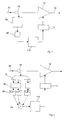
- Fig. 1 schematically depicts an amplifier arrangement connected in a wavelength division multiplexed (WDM) optical communications link.
- the amplifier arrangement includes an active fibre 10 connected at an input side to an upstream optical fibre 20 for receiving traffic signals and at an output side to a downstream optical fibre 30 for transmitting the amplified traffic signals.
- the active fibre 10 is connected to a source of injected optical power 11, specifically a laser pump which pumps optical power into the active fibre 10 and thereby determines the gain of the amplifier.
- the pump power of this laser 11 is controlled by an injection current from a gain controller 110.
- Optical amplifiers that correspond to this configuration include rare earth doped amplifiers, such as erbium-doped amplifiers, fluoride doped amplifiers, Raman and Brillouin amplifiers and the like.
- An optical coupler or fibre tap 40 is connected to the upstream fibre 20 at the input side of the amplifier. This coupler 40 extracts a small amount of the input power from the received traffic signals.
- a filter 50 is connected to this coupler 40 and receives and filters the extracted input signals.
- a photodetector 60 connected to the filter 50 converts the optical signal output by the filter 50 into an electrical signal, preferably a current.
- the photodetector 60 may be a photodiode, phototransistor, or any suitable opto-electric conversion device.
- the photodetector output is fed to the gain controller 110, which in turn adjusts the pump power 11, and thus the gain of the optical amplifier in order to maintain the traffic signal power substantially constant regardless of the number of traffic channels.
- the optical coupler, 40, filter 50, photodetector 60 and gain controller 110 together constitute a feed forward control loop for controlling the gain of the amplifier 10, 11 as a function of the input power.
- the required pump power must be increased more than if a channel centred around 1550 nm is added. This is assuming that the amplifier is driven at a high overall gain.
- the filter 50 compensates for the varying impact on amplifier gain by weighting or attenuating the different wavelengths in the extracted input signal differently.
- the filter 50 is essentially a band pass filter with a transfer function H( ⁇ ) designed to pass the wavelengths of all channels that are or will be transmitted across the optical link with varying degrees of attenuation. More specifically, the transfer function H( ⁇ ) is designed such that the power of signals at selected wavelengths or wavelength bands are attenuated or amplified to compensate for the opposite impact of these wavelengths on the gain of the optical amplifier to which the filter 50 is coupled. It will be appreciated that different classes of amplifier - and possibly individual amplifiers within the same class - will exhibit different gain characteristics across the spectral range of traffic signals.
- the filter transfer function H( ⁇ ) is thus adapted to the specific characteristics of the amplifier utilised.
- a filter 50 connected to an Erbium doped fibre amplifier 10 will preferably have a transfer function that weights signals in the region of the wavelength 1530 higher than signals of wavelengths in the region of 1550 nm.
- signal wavelengths around 1550 are attenuated more than signals of wavelengths of 1530 nm.
- an electrical control signal results. This control signal is used by the gain controller 110 to alter the gain of the amplifier 10 by adjusting the pump power such that the traffic signal gain or gain per channel remains substantially constant.
- the filter 50 is a dielectric filter designed using interference technology to provide a thin film filter that includes a number of quarter wavelength thin films stacked on top of one another, with the wavelengths selected to provide the desired wavelength attenuation pattern corresponding to the optical fibre amplifier utilised.
- the filter could be constituted by a series of fibre Bragg gratings, of single of cascaded Mach-Zehnder interferometers, be of the Fabry-Perot type or be constructed from a combination of the above techniques.
- the filter design is not limited to these examples, but that other appropriate constructions known to the person skilled in the art may also be employed.
- FIG. 2 there is shown an alternative embodiment of the amplifier arrangement according to the invention.
- the basic arrangement shown in Fig. 2 is similar to that depicted in Fig. 1 and like parts have been denoted by like reference numerals.
- Fig. 2 shows an optical fibre amplifier 10 coupled to a source of injected optical energy provided by a laser pump 11, which is controlled by a gain controller 110.
- the active fibre 10 is connected to an input optical fibre 20 and also to an output optical fibre 30.
- a coupler 40 is arranged on the input optical fibre 20 and extracts a small portion of the input signal power.
- This extracted signal is fed to a demultiplexer 70, which is essentially a filter or series of filters arranged to split the signal power into selected wavelength bands designated by ⁇ 1 , ⁇ 2 - ⁇ n . It will be understood that other components may be used in place of the demultiplexor 70. These may include a diffraction grating, a photodiode array, which is described in K. Otsuka et al., ECOC'97, vol. 2, pp 147-150 (1997) or wavelength selective arrays. The optical power in each separate wavelength band ⁇ n is then converted to electrical power using a photodetector 80, similar to the photodetector 60 utilised in the arrangement of Fig. 1.
- the resulting electrical signals are then each fed to a weighting module 90, which is preferably an amplifier.
- Each weighting module 90 amplifies or attenuates the spectrally resolved signal power P 1 , P 2 - P n by applying a predetermined amplitude weighting factor k 1 , k 2 - k n to the signal. It will be appreciated that the weighting modules may attenuate some wavelength bands, amplify other bands and leave some bands substantially unchanged. Hence the term 'amplifier' is used here to signify an amplifier arrangement that can apply a gain of less than unity as well as above unity.
- the number n and width of the wavelength bands ⁇ 1 , ⁇ 2 - ⁇ n may correspond to those of the traffic channels transmitted over the optical link.
- the bands may be narrower or wider than the traffic channels.
- the bands are selected such that signal wavelengths that have a higher than average impact on the gain of the optical amplifier 10 are isolated from the rest, so that they may be amplified or attenuated independently of the other signal wavelengths.
- the weighting factors are determined at or prior to the installation of the amplifier arrangement in the optical link. They are selected to compensate for variations in the gain experienced by different wavelengths passing through the fibre amplifier 10, 11 as a result of the particular characteristics of the amplifier. Taking the example of the Erbium doped fibre amplifier discussed above, this means that signals lying in a wavelength band centred around the wavelength of 1530 nm will be weighted with a higher weighting factor than signals in a wavelength band centred around 1550 nm, such that the resulting signal power of each weighted signal will have the same impact on the amplifier gain.
- the weighted signals are combined in an adder 100 and the total weighted signal power used to control the gain of the amplifier 10 by altering the injection current to the laser pump 11.
- weighting function is performed on electrical signals
- this weighting may be performed instead on optical signals, with the opto-electrical conversion using a photodetector occurring prior to or even after combining the weighted signals.
Landscapes
- Physics & Mathematics (AREA)
- Electromagnetism (AREA)
- Engineering & Computer Science (AREA)
- Computer Networks & Wireless Communication (AREA)
- Signal Processing (AREA)
- Optical Communication System (AREA)
Priority Applications (5)
| Application Number | Priority Date | Filing Date | Title |
|---|---|---|---|
| EP00104153A EP1130818A1 (fr) | 2000-02-29 | 2000-02-29 | Système de communication optique |
| GB0220116A GB2375670B (en) | 2000-02-29 | 2001-02-20 | Optical communication system |
| PCT/EP2001/001915 WO2001065738A2 (fr) | 2000-02-29 | 2001-02-20 | Systeme de communication optique |
| US10/204,236 US6791745B2 (en) | 2000-02-29 | 2001-02-20 | Optical communication system |
| AU2001237406A AU2001237406A1 (en) | 2000-02-29 | 2001-02-20 | Optical communication system |
Applications Claiming Priority (1)
| Application Number | Priority Date | Filing Date | Title |
|---|---|---|---|
| EP00104153A EP1130818A1 (fr) | 2000-02-29 | 2000-02-29 | Système de communication optique |
Publications (1)
| Publication Number | Publication Date |
|---|---|
| EP1130818A1 true EP1130818A1 (fr) | 2001-09-05 |
Family
ID=8167983
Family Applications (1)
| Application Number | Title | Priority Date | Filing Date |
|---|---|---|---|
| EP00104153A Withdrawn EP1130818A1 (fr) | 2000-02-29 | 2000-02-29 | Système de communication optique |
Country Status (5)
| Country | Link |
|---|---|
| US (1) | US6791745B2 (fr) |
| EP (1) | EP1130818A1 (fr) |
| AU (1) | AU2001237406A1 (fr) |
| GB (1) | GB2375670B (fr) |
| WO (1) | WO2001065738A2 (fr) |
Cited By (2)
| Publication number | Priority date | Publication date | Assignee | Title |
|---|---|---|---|---|
| EP2169786A4 (fr) * | 2007-05-31 | 2013-05-29 | Trimatiz Ltd | Amplificateur optique |
| CN112217596A (zh) * | 2020-09-23 | 2021-01-12 | 武汉光迅科技股份有限公司 | 参数调整方法、装置、电子设备和存储介质 |
Families Citing this family (5)
| Publication number | Priority date | Publication date | Assignee | Title |
|---|---|---|---|---|
| DE10358698B4 (de) * | 2003-12-15 | 2015-10-22 | Xieon Networks S.À.R.L. | Verfahren zur Regelung der Pumpleistung eines optischen Verstärkers |
| US7916384B2 (en) * | 2006-05-02 | 2011-03-29 | At&T Intellectual Property Ii, L.P. | Feedback dynamic gain control for a WDM system employing multi wavelength pumped Raman fiber amplifiers |
| US7446932B2 (en) * | 2006-06-15 | 2008-11-04 | At&T Corporation | Method, apparatus and system for cost effective optical transmission with fast Raman tilt transient control |
| US7636192B2 (en) * | 2006-06-15 | 2009-12-22 | At&T Corp. | Method, apparatus and system for cost effective optical transmission with fast Raman tilt transient control |
| CN102026350B (zh) * | 2009-09-23 | 2014-08-13 | 中兴通讯股份有限公司 | 功率调整的方法及终端 |
Citations (3)
| Publication number | Priority date | Publication date | Assignee | Title |
|---|---|---|---|---|
| JPH1012951A (ja) * | 1996-06-18 | 1998-01-16 | Nippon Telegr & Teleph Corp <Ntt> | 光増幅器 |
| US5764404A (en) * | 1994-09-26 | 1998-06-09 | Fujitsu Limited | Wavelength-division-multiplexing optical amplifier |
| US5818629A (en) * | 1995-12-07 | 1998-10-06 | Fujitsu Limited | Method and apparatus for monitoring the momental wavelength of light, and an optical amplifier and an optical communication system which incorporate the method and apparatus to adjust gain tilt |
Family Cites Families (8)
| Publication number | Priority date | Publication date | Assignee | Title |
|---|---|---|---|---|
| JPS6412951A (en) * | 1987-07-06 | 1989-01-17 | Mazda Motor | Roof structure for automobile |
| AU685747B2 (en) * | 1992-06-01 | 1998-01-29 | British Telecommunications Public Limited Company | Filter with preselected attenuation/wavelength characteristic |
| FR2715017B1 (fr) * | 1994-01-13 | 1996-02-16 | Alcatel Nv | Procédé de transmission et liaison optique à multiplexage spectral avec amplification. |
| JPH0918416A (ja) * | 1995-06-28 | 1997-01-17 | Hitachi Ltd | 光増幅器 |
| FR2750750B1 (fr) * | 1996-07-04 | 1998-11-06 | Guerineau Philippe | Dispositif de securite pour desolidariser un arbre mene telescopique, notamment d'une prise de force |
| JP4240551B2 (ja) * | 1997-03-19 | 2009-03-18 | 富士通株式会社 | 光増幅装置 |
| JPH10285143A (ja) * | 1997-04-09 | 1998-10-23 | Nec Corp | 光増幅装置 |
| JP2000312046A (ja) * | 1999-04-27 | 2000-11-07 | Hitachi Ltd | 光伝送装置、光増幅装置、および光伝送システム |
-
2000
- 2000-02-29 EP EP00104153A patent/EP1130818A1/fr not_active Withdrawn
-
2001
- 2001-02-20 AU AU2001237406A patent/AU2001237406A1/en not_active Abandoned
- 2001-02-20 WO PCT/EP2001/001915 patent/WO2001065738A2/fr not_active Ceased
- 2001-02-20 US US10/204,236 patent/US6791745B2/en not_active Expired - Lifetime
- 2001-02-20 GB GB0220116A patent/GB2375670B/en not_active Expired - Fee Related
Patent Citations (3)
| Publication number | Priority date | Publication date | Assignee | Title |
|---|---|---|---|---|
| US5764404A (en) * | 1994-09-26 | 1998-06-09 | Fujitsu Limited | Wavelength-division-multiplexing optical amplifier |
| US5818629A (en) * | 1995-12-07 | 1998-10-06 | Fujitsu Limited | Method and apparatus for monitoring the momental wavelength of light, and an optical amplifier and an optical communication system which incorporate the method and apparatus to adjust gain tilt |
| JPH1012951A (ja) * | 1996-06-18 | 1998-01-16 | Nippon Telegr & Teleph Corp <Ntt> | 光増幅器 |
Non-Patent Citations (1)
| Title |
|---|
| PATENT ABSTRACTS OF JAPAN vol. 1998, no. 05 30 April 1998 (1998-04-30) * |
Cited By (2)
| Publication number | Priority date | Publication date | Assignee | Title |
|---|---|---|---|---|
| EP2169786A4 (fr) * | 2007-05-31 | 2013-05-29 | Trimatiz Ltd | Amplificateur optique |
| CN112217596A (zh) * | 2020-09-23 | 2021-01-12 | 武汉光迅科技股份有限公司 | 参数调整方法、装置、电子设备和存储介质 |
Also Published As
| Publication number | Publication date |
|---|---|
| WO2001065738A2 (fr) | 2001-09-07 |
| US6791745B2 (en) | 2004-09-14 |
| GB0220116D0 (en) | 2002-10-09 |
| GB2375670B (en) | 2004-08-04 |
| AU2001237406A1 (en) | 2001-09-12 |
| GB2375670A (en) | 2002-11-20 |
| US20030053200A1 (en) | 2003-03-20 |
| WO2001065738A3 (fr) | 2002-03-07 |
Similar Documents
| Publication | Publication Date | Title |
|---|---|---|
| EP0907993B1 (fr) | Modules d'amplificateurs optiques | |
| US6606188B2 (en) | Optical repeater using raman amplification, wavelength division multiplexed light transmission system, excitation light supply method and excitation light control method for raman amplification | |
| US7995269B2 (en) | Cost effective optical transmission with fast raman tilt transient control | |
| CA2649501C (fr) | Controle dynamique de gain avec retour ameliore pour circuit wdm employant des amplificateurs a fibres de raman a pompage en multiples longueurs d'onde | |
| EP1909414B1 (fr) | Compensation dynamique de l'inclinaison Raman | |
| US6690504B1 (en) | System and method for controlling spectral distribution of output power in a Raman amplifier | |
| Giles et al. | Dynamic gain equalization in two-stage fiber amplifiers | |
| US7554719B2 (en) | Fast dynamic gain control in an optical fiber amplifier | |
| US7554718B2 (en) | Fast dynamic gain control in an optical fiber amplifier | |
| US6791745B2 (en) | Optical communication system | |
| US20030035206A1 (en) | Optical power transient control scheme for EDFA amplifiers | |
| US7769302B1 (en) | Method and apparatus for adjusting for polarization-induced, optical signal transients | |
| EP1788730B1 (fr) | Dispositif d'amplification optique avec compensation d'inclination de perte de tronçons | |
| US20070109626A1 (en) | Fast Dynamic Gain Control in a Bidirectionally-Pumped Raman Fiber Amplifier | |
| US6917467B2 (en) | Optical amplifier | |
| US7636192B2 (en) | Method, apparatus and system for cost effective optical transmission with fast Raman tilt transient control | |
| Zhou et al. | Submicrosecond transient control for a forward-pumped Raman fiber amplifier | |
| US7277221B2 (en) | Fast dynamic gain control in cascaded Raman fiber amplifiers | |
| GB2383209A (en) | Raman optical amplifier with two power control loops | |
| US20070109623A1 (en) | Fast Dynamic Gain Control in a Bidirectionally-Pumped Raman Fiber Amplifier |
Legal Events
| Date | Code | Title | Description |
|---|---|---|---|
| PUAI | Public reference made under article 153(3) epc to a published international application that has entered the european phase |
Free format text: ORIGINAL CODE: 0009012 |
|
| AK | Designated contracting states |
Kind code of ref document: A1 Designated state(s): AT BE CH CY DE DK ES FI FR GB GR IE IT LI LU MC NL PT SE |
|
| AX | Request for extension of the european patent |
Free format text: AL;LT;LV;MK;RO;SI |
|
| AKX | Designation fees paid | ||
| REG | Reference to a national code |
Ref country code: DE Ref legal event code: 8566 |
|
| STAA | Information on the status of an ep patent application or granted ep patent |
Free format text: STATUS: THE APPLICATION IS DEEMED TO BE WITHDRAWN |
|
| 18D | Application deemed to be withdrawn |
Effective date: 20020306 |