EP1130840A2 - Modulation multiporteuse à étalage du spectre pour la communication cellulaire - Google Patents
Modulation multiporteuse à étalage du spectre pour la communication cellulaire Download PDFInfo
- Publication number
- EP1130840A2 EP1130840A2 EP01301710A EP01301710A EP1130840A2 EP 1130840 A2 EP1130840 A2 EP 1130840A2 EP 01301710 A EP01301710 A EP 01301710A EP 01301710 A EP01301710 A EP 01301710A EP 1130840 A2 EP1130840 A2 EP 1130840A2
- Authority
- EP
- European Patent Office
- Prior art keywords
- frequency division
- spectrum spreading
- orthogonal frequency
- circuit
- receiver apparatus
- Prior art date
- Legal status (The legal status is an assumption and is not a legal conclusion. Google has not performed a legal analysis and makes no representation as to the accuracy of the status listed.)
- Withdrawn
Links
Images


Classifications
-
- H—ELECTRICITY
- H04—ELECTRIC COMMUNICATION TECHNIQUE
- H04L—TRANSMISSION OF DIGITAL INFORMATION, e.g. TELEGRAPHIC COMMUNICATION
- H04L5/00—Arrangements affording multiple use of the transmission path
- H04L5/02—Channels characterised by the type of signal
- H04L5/023—Multiplexing of multicarrier modulation signals, e.g. multi-user orthogonal frequency division multiple access [OFDMA]
-
- H—ELECTRICITY
- H04—ELECTRIC COMMUNICATION TECHNIQUE
- H04B—TRANSMISSION
- H04B7/00—Radio transmission systems, i.e. using radiation field
- H04B7/02—Diversity systems; Multi-antenna system, i.e. transmission or reception using multiple antennas
- H04B7/04—Diversity systems; Multi-antenna system, i.e. transmission or reception using multiple antennas using two or more spaced independent antennas
- H04B7/08—Diversity systems; Multi-antenna system, i.e. transmission or reception using multiple antennas using two or more spaced independent antennas at the receiving station
- H04B7/0837—Diversity systems; Multi-antenna system, i.e. transmission or reception using multiple antennas using two or more spaced independent antennas at the receiving station using pre-detection combining
- H04B7/0842—Weighted combining
- H04B7/086—Weighted combining using weights depending on external parameters, e.g. direction of arrival [DOA], predetermined weights or beamforming
-
- H—ELECTRICITY
- H04—ELECTRIC COMMUNICATION TECHNIQUE
- H04L—TRANSMISSION OF DIGITAL INFORMATION, e.g. TELEGRAPHIC COMMUNICATION
- H04L1/00—Arrangements for detecting or preventing errors in the information received
- H04L1/0001—Systems modifying transmission characteristics according to link quality, e.g. power backoff
- H04L1/0002—Systems modifying transmission characteristics according to link quality, e.g. power backoff by adapting the transmission rate
- H04L1/0003—Systems modifying transmission characteristics according to link quality, e.g. power backoff by adapting the transmission rate by switching between different modulation schemes
Definitions
- the present invention is related generally to a transmitter apparatus, a receiver apparatus and a base station implemented with the transmitter and receiver apparatuses which are communicated with each other by making use of an orthogonal frequency division demultiplexing modulation and a spectrum spreading modulation in combination.
- OFDM Orthogonal Frequency Division Multiplexing
- OFDM is a technique with which the problem of the interference due to delay spread can be solved.
- OFDM is a block-oriented modulation scheme that maps data symbols onto a plurality of orthogonal sub-carriers separated by a distance to provide excellent resistance characteristics against the interference due to delay spread through the multipaths.
- OFDM is capable of compacting a substantially larger number of sub-carriers, as compared with a conventional FDM (Frequency Division Multiplexing), to provide an extremely high utilization of the frequency resources.
- OFDM is employed as a signal transmission scheme for digital broadcast in Europe, U.S.A. and Japan, and, in addition to this, determined to be employed as part of the standard for wireless system such as HIPER-LAN/2 (Europe), IEEE802.11a (U.S.A.), MMAC (Japan) which are the next generations of the mobile communication systems.
- the next generations of the wireless communication system are expected to support high speed signal transmission rates in the order of several Mbps to several tens of Mbps with a wider bandwidth exclusively occupied by each channel. Because of this, it becomes furthermore important to improve the utilization of the frequency resources as compared with conventional systems. Furthermore, because of the limitation on the frequency resources as available, a technical object resides in how to determine an effective arrangement of the frequency resources and an effective arrangement of the respective cells in the cellular system.
- next generations of the wireless communication system are expected to support different signal transmission rates to accommodate a variety of information types for use in multimedia communications which require different levels of QoS (Quality of Service).
- the support for different signal transmission rates can be implemented by the use of different modulation systems and different encoding rates.
- Such a system capable of supporting different signal transmission rates is called as "a multi-rate supporting system" in the following description.
- the following table shows the relationship among the transfer speeds, the encoding rates, the modulation schema and the receiver sensitivities.
- Exemplary prior art dynamic cell structure systems are described in "Studies of Zone Generation Algorithm in Adaptive Variable Zone Structure System", Institute of Electronics, Information and Communication Engineers, B-5-204, 1998 and described in “Studies of Adaptive Variable Zone Structure System Implemented with a Directional Antenna in a Base Station", Communications Society Conference, B-5-81, 1998.
- it is accomplished to lessen the load on a base station due to disparity of the number of mobile stations to be linked with the base station and decrease the distance between adjacent zones utilizing the same frequency by making use of an adaptive array antenna and adaptively modifying the profile of the zone in accordance with the distribution of mobile stations.
- the system becomes more flexible as the variable range of the coverage of a cell is increased in the dynamic cell structure system. For this reason, it is a technical issue how to expand the variable range of the coverage of a cell.
- the utilization of the frequency resources has to be improved in a wireless communication system.
- the frequency resources as available are limited so that an appropriate system design is required to accomplish highly utilization of the frequency resources.
- the intelligent antenna is a wireless communication system improving the utilization of channels.
- the intelligent antenna technology has been explained, for example, in “Intelligent Antenna Technology", Communications Society Conference Vol.1. TB-5-1. 1999.
- the exemplary prior art dynamic cell structure systems as described in "Studies of Zone Generation Algorithm in Adaptive Variable Zone Structure System” and “Studies of Adaptive Variable Zone Structure System Implemented with a Directional Antenna in a Base station” are also examples of application of the intelligent antenna.
- the exemplary prior art as described in "Unnecessary Waves Suppression Characteristics for Multi Carrier - CMA Adaptive Array” is an example of application of the intelligent antenna to the OFDM system.
- the respective signals as received through a plurality of antenna elements are appropriately weighted and then synthesized by means of a synthesizer.
- the signals as synthesized are converted into the signals in the frequency domain by means of FFT.
- the weight factor is determined on the basis of CMA (Constant Modules Algorithm) in order to make equal all the amplitudes of the respective sub-carriers .
- CMA Constant Modules Algorithm
- the reception electric field strength as required is depending on the signal transmission rate in the case of the multi-rate supporting system. For this reason, it is important how to effectively control the weight factors given to an adaptive array antenna in such an environment where different coverages are given to users.
- the communication range is expanded by the antenna gain as obtained by directing the beam from an adaptive array antenna to the target mobile station
- the antenna is controlled in order to appropriately direct the beam on the basis of the information obtained from the received signals.
- the next generations of the wireless communication system are expected to support high speed signal transmission rates in the order of several Mbps to several tens of Mbps with a wider bandwidth exclusively occupied by each channel. Because of this, it becomes indispensable to improve the utilization of the frequency resources as compared with conventional systems. Furthermore, because of the limitation on the frequency resources as available, the technical object resides in the arrangement of the frequency resources and the arrangement of the respective cells in the cellular system.
- the system becomes more flexible as the variable range of the coverage of a cell is increased in the dynamic cell structure system. For this reason, it is a technical issue to expand the variable range of the coverage of a cell. Furthermore, it is inevitable that the interference with an adjacent cell is increased while the coverage of a cell is expanded. Namely, it shall not be the case that the interference with an adjacent cell is increased while the coverage of a cell is expanded. From this fact, it is a technical issue how to arrange cells in the dynamic zone structure.
- the present invention has been made in order to solve the shortcomings as described heretofore. It is an object of the present invention to provide a transmitter apparatus, a receiver apparatus and a base station implemented with the transmitter and receiver apparatuses in which it is possible to expand the variable range of the coverage of a cell in the dynamic cell structure system.
- a new and improved transmitter apparatus making use of an orthogonal frequency division multiplexing modulation and a spectrum spreading modulation in combination
- an orthogonal frequency division multiplexing circuit which selectively modulates information signals to be transmitted by orthogonal frequency division multiplexing; a spectrum spreading circuit which selectively performs a spectrum spreading modulation of said information signals to be transmitted; and a transmission signal processing circuit which transfers said information signals which have been modulated by either said orthogonal frequency division multiplexing modulation or said spectrum spreading modulation to a receiver apparatus as a transmission signal, wherein, when said receiver apparatus and said transmitter apparatus are located so close to each other that the received signal level of said receiver apparatus is sufficient to maintain the communication between said receiver apparatus and said transmitter apparatus with signals which are modulated on the basis of said orthogonal frequency division multiplexing modulation but not modulated on the basis of said spectrum spreading modulation, said orthogonal frequency division multiplexing circuit performs the modulation of said information signals to be transmitted while said spectrum spreading circuit does
- said orthogonal frequency division multiplexing circuit is provided with a serial-to-parallel converter which converts said information signals to be transmitted from a serial data sequence to a parallel data sequence, a modulator which serves to map said parallel data as converted by said serial-to-parallel converter onto symbols in the frequency domain, an inverse fast Fourier transform unit which performs the inverse fast Fourier transformation of said information signals as mapped and a parallel-to-serial converter which converts the output data sequence of the IFFT unit 16 from a parallel data sequence to a serial data sequence.
- said spectrum spreading circuit is provided with a spectrum spreading pattern generation circuit which generates a plurality of spectrum spreading patterns for use in said spectrum spreading modulation.
- said transmission signal processing circuit is provided with an adaptive array antenna and wherein, when said receiver apparatus and said transmitter apparatus are located so remote from each other that the received signal level of said receiver apparatus is not sufficient to maintain the communication between said receiver apparatus and said transmitter apparatus with signals which are modulated on the basis of said or thogonal frequency division multiplexing modulation but not modulated on the basis of said spectrum spreading modulation, the direction of said receiver apparatus relative to said transmitter apparatus is detected by making use of a transmission signal which is modulated by said spectrum spreading modulation, followed by directing a beam of the adaptive array antenna to said mobile station to increase the received signal level of said receiver apparatus and make it possible to perform the communication between said receiver apparatus and said transmitter apparatus by orthogonal frequency division multiplexing.
- a new and improved transmitter apparatus making use of orthogonal frequency division multiplexing modulations and a spectrum spreading modulation in combination
- an orthogonal frequency division multiplexing circuit which performs a first orthogonal frequency division multiplexing modulation of information signals to be transmitted
- a spectrum spreading circuit which selectively performs a spectrum spreading modulation of the output of said orthogonal frequency division multiplexing circuit
- a transmission signal processing circuit which transfers the output of said spectrum spreading circuit to a receiver apparatus as a transmission signal, wherein, when said receiver apparatus and said transmitter apparatus are located so close to each other that the received signal level of said receiver apparatus is sufficient to maintain the communication between said receiver apparatus and said transmitter apparatus with signals which are modulated by said first orthogonal frequency division multiplexing modulation but not modulated on the basis of said spectrum spreading modulation, said orthogonal frequency division multiplexing circuit performs said first orthogonal frequency division multiplexing modulation while said spectrum spreading circuit does not
- said orthogonal frequency division multiplexing circuit serves to perform a phase shift keying modulation of said information signals.
- a new and improved transmitter apparatus making use of orthogonal frequency division multiplexing modulations and a spectrum spreading modulation in combination
- a mapping circuit which serves to map information signals to be transmitted onto symbols in the frequency domain suitable for a first orthogonal frequency division multiplexing modulation
- a spectrum spreading circuit which selectively performs a spectrum spreading modulation of the output of said mapping circuit
- an orthogonal frequency division multiplexing circuit which performs said first orthogonal frequency division multiplexing modulation of the output signal of said spectrum spreading circuit
- a transmission signal processing circuit which transfers the output of said orthogonal frequency division multiplexing circuit to a receiver apparatus as a transmission signal, wherein, when said receiver apparatus and said transmitter apparatus are located so close to each other that the received signal level of said receiver apparatus is sufficient to maintain the communication between said receiver apparatus and said transmitter apparatus with signals which are modulated by said first orthogonal frequency division multiplexing modulation but not modulated on the basis of said
- said transmission signal processing circuit is provided with an adaptive array antenna and wherein, when said receiver apparatus and said transmitter apparatus are located so remote from each other that the received signal level of said receiver apparatus is not sufficient to maintain the communication between said receiver apparatus and said transmitter apparatus with signals which are modulated on the basis of said orthogonal frequency division multiplexing modulation but not modulated on the basis of said spectrum spreading modulation, the direction of said receiver apparatus relative to said transmitter apparatus is detected by making use of a transmission signal which is modulated by said spectrum spreading modulation, followed by directing a beam of the adaptive array antenna to said mobile station to increase the received signal level of said receiver apparatus and make it possible to perform the communication between said receiver apparatus and said transmitter apparatus by said first orthogonal frequency division multiplexing modulations.
- a new and improved receiver apparatus making use of an orthogonal frequency division demultiplexing demodulation and an inverse spectrum spreading demodulation in combination
- an inverse spectrum spreading circuit which selectively demodulates information signals transmitted from a transmitter apparatus and received by said receiver apparatus by performing inverse spectrum spreading demodulation of said information signals
- an orthogonal frequency division demultiplexing circuit which selectively demodulates said information signals; wherein, when said receiver apparatus and said transmitter apparatus are located so close to each other that the received signal level of said receiver apparatus is sufficient to maintain the communication between said receiver apparatus and said transmitter apparatus with signals which are demodulated on the basis of said orthogonal frequency division demultiplexing demodulation but not demodulated on the basis of said inverse spectrum spreading demodulation, said orthogonal frequency division demultiplexing circuit performs the demodulation of information signals as received while said inverse spectrum spreading circuit does not perform said inverse spectrum spreading demodulation of said information signals as received,
- said orthogonal frequency division demultiplexing circuit serves also to perform a phase shift keying demodulation of said information signals as received.
- a new and improved receiver apparatus making use of an orthogonal frequency division demultiplexing demodulation and an inverse spectrum spreading demodulation in combination
- an orthogonal frequency division demultiplexing circuit which demodulates information signals transmitted from a transmitter apparatus and received by said receiver apparatus on the basis of a first orthogonal frequency division demultiplexing demodulation; an inverse spectrum spreading circuit which selectively demodulates the output of said orthogonal frequency division demultiplexing circuit by performing inverse spectrum spreading demodulation of said information signals as demultiplexed; wherein, when said receiver apparatus and said transmitter apparatus are located so close to each other that the received signal level of said receiver apparatus is sufficient to maintain the communication between said receiver apparatus and said transmitter apparatus with signals which are demodulated on the basis of said first orthogonal frequency division demultiplexing demodulation but not demodulated on the basis of said inverse spectrum spreading demodulation, said orthogonal frequency division demultiplexing circuit perform
- a new and improved receiver apparatus making use of an orthogonal frequency division demultiplexing demodulation and an inverse spectrum spreading demodulation in combination
- an orthogonal frequency division demultiplexing circuit which selectively demodulates information signals transmitted from a transmitter apparatus and received by said receiver apparatus by performing an orthogonal frequency division demultiplexing demodulation of said information signals
- an inverse spectrum spreading circuit which selectively demodulates the output of said orthogonal frequency division demultiplexing circuit by performing inverse spectrum spreading demodulation of the information signals as received
- a demapping circuit which serves to selectively demap said information signals as demodulated by said orthogonal frequency division demultiplexing demodulation from symbols in the frequency domain suitable for said orthogonal frequency division demultiplexing demodulation; wherein, when said receiver apparatus and said transmitter apparatus are located so close to each other that the received signal level of said receiver apparatus is sufficient to maintain the communication between said receiver apparatus and said transmitter apparatus with
- said inverse spectrum spreading circuit is provided with a spectrum spreading pattern generation circuit which generates a plurality of spectrum spreading patterns for use in said inverse spectrum spreading demodulation.
- said orthogonal frequency division demultiplexing circuit is provided with a serial-to-parallel converter which converts the information signals as received from a serial data sequence to a parallel data sequence and a fast Fourier transform unit which performs the fast Fourier transformation of said information signals as converted to said parallel data sequence.
- said inverse spectrum spreading circuit makes use of different spectrum spreading patterns for different transmitter apparatuses.
- a new and improved base station which serves to establish communication with at least one mobile station located in a communication area where said base station is responsible for communication by making use of an orthogonal frequency division multiplexing modulation and a spectrum spreading modulation in combination
- a transmitter apparatus capable of transmitting information signals in a first transmission mode which has a first transmission speed and a first gain and transmitting information signals in a second transmission mode which has a second transmission speed which is lower than said first transmission speed and a second gain which is greater than said first gain
- a receiver apparatus capable of receiving a first reception mode which receives information signals having been transmitted in said first transmission mode and receiving a second reception mode which receives information signals having been transmitted in said second transmission mode; wherein, when said mobile station and said base station are located so close to maintain communication between said mobile station and said base station in said first transmission mode and said first reception mode, said base station maintains communication between said mobile station and said base station in said first transmission mode
- said base station makes use of said second transmission mode and said second reception mode for communication with a mobile station which is located in an overlapping area between said communication area where said base station is responsible for communication and an adjacent area where an adjacent base station is responsible for communication.
- further improvement resides in that said base station and an adjacent base station thereto share the same communication resources for said first transmission mode and said first reception mode respectively and make use of separate communication resources for said second transmission mode and said second reception mode respectively.
- said base station is provided with an adaptive array antenna and wherein , when said mobile station and said base station are located so remote from each other that the received signal level of said base station is not sufficient to maintain the communication between said mobile station and said base station in said first transmission mode and said first reception mode, said base station establishes communication with said mobile station in said second transmission mode and said second reception mode, detects the direction of said mobile station relative to said base station, directing a beam of the adaptive array antenna to said mobile station in order to improve the gain in said first transmission mode and said first reception mode, and then establishing communication with said mobile station in said first transmission mode and said first reception mode.
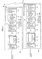
- Fig.1 is a block diagram showing a transmitter apparatus and a receiver apparatus in accordance with a first embodiment of the present invention.
- the transmitter apparatus and the receiver apparatus in accordance with the present invention are provided for wireless communication by the use of OFDM (Orthogonal Frequency Division Multiplexing).
- OFDM Orthogonal Frequency Division Multiplexing
- the transmitter apparatus 10a in accordance with the first embodiment of the present invention is composed of a serial-to-parallel converter 12 for converting the information signals (data stream) to be transmitted from a serial data sequence to a parallel data sequence, a modulator 14 for mapping the parallel data as outputted from the serial-to-parallel converter 12 onto symbols in the frequency domain, an IFFT (Inverse Fast Fourier Transform) unit 16 for converting the signals in the frequency domain as outputted from the modulator 14 to the signals in the time domain, a parallel-to-serial converter 18 for converting the output data sequence of the IFFT unit 16 from a parallel data sequence to a serial data sequence, a spectrum spreading circuit 20 for spectrum spreading the output signals of the parallel-to-serial converter 18, a guard interval inserting circuit 22 for inserting guard intervals which are timely gaps to the output signals of the spectrum spreading circuit 20 for the purpose of preventing interference due to multipaths, a transmission signal processing circuit 24 for performing necessary processes required to transmit the output signals of the
- the transmitter apparatus 10a in accordance with the first embodiment has a pattern generation circuit 44a provided in the spectrum spreading circuit 20 for generating spectrum spreading signals (spectrum spreading pattern) which are multiplied by the output signals of the parallel-to-serial converter 18 when the spectrum spreading circuit 20 performs spectrum spreading, and a mapping table 46 provided in the modulator 14 for storing numbers to be mapped corresponding to the parallel data as outputted from the serial-to-parallel converter 12.
- the transmitter circuit 10a is provided with a control circuit for taking control of the spectrum spreading circuit 20 as to whether or not spectrum spreading is performed.
- the control circuit serves to output an appropriate control signal to the spectrum spreading circuit 20 in order to take control of the spectrum spreading process by the spectrum spreading circuit 20.
- the receiver apparatus 10b in accordance with the first embodiment of the present invention is composed of an antenna 28 for receiving radio waves as radiated from the transmitter apparatus 10a, a received signal processing circuit 30 for performing processes to convert radio frequency signals to corresponding baseband signals, a guard interval removal circuit 32 for removing the guard intervals in synchronism with the timing information as obtained from the decoded signals, an inverse spectrum spreading circuit 34 for inverse spectrum spreading the output signals of the guard interval removal circuit 32, a serial-to-parallel converter 36 for converting the output signals of the spectrum spreading circuit 34 from a serial data sequence to a parallel data sequence, an FFT (Fast Fourier Transform) unit 38 for converting the parallel data as output from the serial-to-parallel converter 36 from signals in the time domain to signals in the frequency domain, a demodulator unit 40 for demapping the signals as outputted from the FFT unit 38 in the frequency domain, and a parallel-to-serial converter 42 for converting the output signals of the demodulator unit 40 from
- the receiver apparatus 10b in accordance with the first embodiment is composed of the pattern generation circuit 44b provided in the inverse spectrum spreading circuit 34 for generating the identical patterns as used by the spectrum spreading circuit 20 of the transmitter apparatus 10a, and a demapping table 47 provided in the demodulator unit 40 for storing the identical numbers as stored in the mapping table 46 of the transmitter apparatus 10a.
- the receiver circuit 10b is provided with a control circuit for taking control of the inverse spectrum spreading circuit 34 as to whether or not inverse spectrum spreading is performed. This control circuit serves to output an appropriate control signal to the inverse spectrum spreading circuit 34 in order to take control of the inverse spectrum spreading process by the inverse spectrum spreading circuit 34.
- Fig.2 is a schematic diagram showing an exemplary configuration of cells in accordance with the conventional cellular system.
- a plurality of base stations 48n-1, 48n and 48n+1 are located in the service area covered by cells 50n-1, 50n and 50n+1 in which radio waves are effectively propagated from the respective base stations 48n-1, 48n and 48n+1.
- the base stations 48n-1, 48n and 48n+1 are responsible for resource management of wireless frequencies and so forth within the respective cells 50n-1, 50n and 50n+1.
- the respective base stations 48n-1, 48n and 48n+1 and the respective mobile stations 52m-1, 52m and 52m+1 are provided with usual transmitter apparatuses and receiver apparatuses.
- the so-called cellular system is such a system in which wireless resources are allocated to the respective base stations 48n-1, 48n and 48n+1 and the respective mobile stations 52m-1, 52m and 52m+1.
- the timing control of the signals for use in the communication system is depending upon the channel allocation algorithm which is employed in the communication system.
- Fig.3 is a schematic diagram showing an exemplary configuration of the burst frame for the TDMA system in which time slots are allocated to the respective channels by timely division for multiplexing.
- the abscissa is indicative of time.
- the burst frame as illustrated in Fig.3 consists of a broadcast channel 54 through which common information is broadcasted from a base station to all the mobile stations linked to the base station, a downlink channel 56 through which information items exclusive to the respective mobile stations are transfered from the base station to the individual mobile stations, an uplink channel 58 through which information items are transfered from the respective mobile stations to the base station, and a random access channel 60 through which a mobile station can transfer a request for allocation of wireless resources to the base station.
- the respective channels 54, 56, 58 and 60 are composed of a plurality of slots respectively.
- the mobile station located within the service area is in communication with the base station through predetermined slots in the downlink channel 56 and the uplink channel 58 which have been allocated to the mobile station by the base station.
- the modulation scheme and the signal transmission rate for use in communications between the base station and the respective mobile stations are fixed in advance.
- the modulation scheme and the signal transmission rate for use therein have been defined as quadrature phase shift keying (QPSK) modulation and 32 kbps respectively.
- QPSK quadrature phase shift keying
- the next generations of the wireless communication system are designed to support different signal transmission rates to accommodate a variety of information types for use in multimedia communications which require different levels of QoS (Quality of Service). More specifically speaking, the support for different signal transmission rates can be implemented by the use of different modulation systems and different encoding rates. Namely, the multi-rate supporting system is employed in the next generations of the wireless communication system.
- the multi-rate supporting system serves to accommodate users requiring different signal transmission rates and therefore particularly fitted for multimedia information. Also, since an appropriate signal transmission rate can be used in accordance with the wireless communication environment, the utilization of the frequency resources can be improved. Furthermore, the coverage of a cell can be varied by changing the signal transmission rate. The system becomes more flexible as the variable range of the coverage of a cell is increased in the dynamic cell structure system. For this reason, it is a technical issue to expand the variable range of the coverage of a cell as explained in the prior art technique.
- Fig.4 is an explanatory view for explaining the coverage of the cell of the base station in accordance with the first embodiment of the present invention.
- the base station 62 of the first embodiment of the present invention serves to provide an ordinary coverage 66 and a spreading coverage 68.
- the base station 62 performs conventional OFDM in the ordinary coverage 66 in which the mobile stations 64a and 64b maintain communication with the base station 62 on the basis of the OFDM.
- the base station 62 serves to provide the spreading coverage 68 surrounding the ordinary coverage 66 for performing conventional OFDM, and can establish communication with a mobile station 64c located outside of the ordinary coverage 66 but inside of the spreading coverage 68.
- the transmitter apparatus 10a in accordance with the first embodiment of the present invention is provided with the spectrum spreading circuit 20 between the parallel-to-serial converter 18 and the guard interval inserting circuit 22 while the receiver apparatus 10b is provided with the inverse spectrum spreading circuit 34 between the guard interval removal circuit 32 and the serial-to-parallel converter 36.
- the spectrum spreading circuit 20 of the transmitter apparatus 10a serves to spread the respective transmission signals by multiplying the transmission signals by a pattern as generated by the pattern generation circuit 44a.
- the spectrum spreading circuit 34 serves to inverse spread the respective received signals by multiplying the received signals as spectrum spread by a pattern as generated by the pattern generation circuit 44b.
- the pattern as generated by the pattern generation circuit 44a for the multiply operation is identical to the pattern as generated by the pattern generation circuit 44b for the multiply operation.
- Fig.5 and Fig.6 are explanatory views for explaining the processing of the signals in the transmitter apparatus 10a and the receiver apparatus 10b as illustrated in Fig.1.
- Fig.5 is explanatory view for explaining the processing of the signals in the case where the spectrum spreading operation is not performed as well as the inverse spectrum spreading operation.
- Fig.6 is explanatory view for explaining the processing of the signals in the case where the spectrum spreading operation is performed as well as the inverse spectrum spreading operation.
- the case where the spectrum spreading operation is not performed as well as the inverse spectrum spreading operation is such a case where the receiver apparatus and the transmitter apparatus are located so close to each other that the receiver sensitivity is sufficient to maintain the communication between the receiver apparatus and the transmitter apparatus by means of OFDM without spectrum spreading.
- the transmitter apparatus 10a serves to generate conventional OFDM signals. More specifically speaking, the conventional OFDM signals are generated by mapping data symbols onto the complex plane in the frequency domain (see spectral components 70) by means of the modulator 14 of the transmitter apparatus 10a, and converting the data symbols as mapped to signals in the time domain by means of the IFFT unit 18. The OFDM signals are generated to effectively occupy the entirety of the available bandwidth.
- the spectrum spreading circuit 20 serves to output the input signals without change so that the transmitter apparatus 10a then outputs the signals with spectra 74.
- the transmitter apparatus 10a serves to generate OFDM signals.
- the modulator 14 serves to decrease the number of the data symbols as mapped onto the complex plane in the frequency domain (see spectral components 80). In this case, only one sub-carrier is modulated while NULL is assigned to the remaining sub-carriers. OFDM is therefore not performed in fact in this case. Accordingly, the OFDM signals as converted in the time domain by the IFFT unit 16 has spectral components 82. If the number of the available sub-carriers of the OFDM signals is N, 1/N of the available bandwidth is used by the spectral components 82. Accordingly, the transfer speed is also decreased by 1/N.
- the spectrum spreading circuit 20 then multiplies the input signals by a predetermined pattern (s).
- the transmission signal processing circuit 24 serves to amplify the signals to a sufficient power level and output the amplified signals. Accordingly, the transmitter apparatus 10a outputs the OFDM has spectrum spread with the spectral components 84 of which effective bandwidth is equal to that of the spectral components 74 as illustrated in Fig.5.
- the receiver apparatus 10b usually skips the inverse spectrum spreading process, but only when communication can not be established, it performs the inverse spectrum spreading process in advance of demodulation.
- the inverse spectrum spreading circuit 34 of the receiver apparatus 10b serves to switch the inverse spreading pattern among from a plurality of predetermined patterns to search the inverse spreading pattern, that is identical to the spreading pattern having been used in the transmitter apparatus 10a, for inverse spreading the received signals (see the spectral components 86).
- the inverse spectrum spreading circuit 34 then performs the inverse spectrum spreading process of the received signals by the use of the inverse spreading pattern identical to the spreading pattern having been used in the transmitter apparatus 10a. Accordingly, the inverse spectrum spreading circuit 34 outputs the signals with spectral components 88.
- the spectral components 88 is corresponding to the spectral components 78 in the case where the inverse spectrum spreading operation is not performed.
- the receiver sensitivity can be improved by the spectrum spreading gain since the OFDM signals are spectrum spread at the transmitter apparatus and spectrum de-spread at the receiver apparatus. Because of this, it is possible to expand the variable range of the coverage of a cell in the dynamic cell structure system.
- the transmitter/reception apparatus it is possible to implement the transmitter/reception apparatus only by partly modifying an existing system and therefore to reduce the initial cost as required when the new system is introduced.
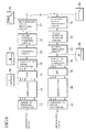
- Fig.7 is a block diagram showing a transmitter apparatus and a receiver apparatus in accordance with a second embodiment of the present invention.
- the transmitter apparatus and the receiver apparatus in accordance with the present invention are provided for wireless communication by the use of the OFDM technique in the same manner as the first embodiment.
- the OFDM modulation and the spectrum spreading process are not performed to the same signals in combination.
- the OFDM modulation and the spectrum spreading process are performed to the same signals.
- the signals in the frequency domain are spectrum spread or inverse spectrum spread.
- the spectrum spreading circuit 20 as illustrated in Fig.1 is connected between the parallel-to-serial converter 18 and the guard interval inserting circuit 22 while the inverse spectrum spreading circuit 34 is connected between the guard interval removal circuit 32 and the serial-to-parallel converter 36.
- the spectrum spreading process and the inverse spectrum spreading process are linear operations and can be performed in the time domain.
- the spectrum spreading process and the inverse spectrum spreading process are performed in the time domain.
- the transmitter apparatus 10a in accordance with the second embodiment of the present invention is composed of a serial-to-parallel converter 12 for converting the information signal (data stream) to be transmitted from a serial data sequence to a parallel data sequence, a modulator 14 for mapping the parallel data as outputted from the serial-to-parallel converter 12 onto symbols in the frequency domain, a spectrum spreading circuit 140 for spectrum spreading the output signals of the modulator 14, an IFFT (Inverse Fast Fourier Transform) unit 16 for converting the signals in the frequency domain as outputted from the spectrum spreading circuit 140 to the signals in the time domain, a parallel-to-serial converter 18 for converting the output data sequence of the IFFT unit 16 from a parallel data sequence to a serial data sequence, a guard interval inserting circuit 22 for inserting guard intervals which are timely gaps to the output signals of the parallel-to-serial converter 18 for the purpose of preventing interference due to multipaths, a transmission signal processing circuit 24 for performing necessary processes required to transmit the output signals of
- the transmitter apparatus 10a in accordance with the second embodiment is provided with a pattern generation circuit 144a in the spectrum spreading circuit 140 for generating spectrum spreading signals (spectrum spreading patterns) which are multiplied by the output signals of the modulator 14 when the spectrum spreading circuit 140 performs spectrum spreading, and a mapping table 46 provided in the modulator 14 for storing numbers to be mapped corresponding to the parallel data as outputted from the serial-to-parallel converter 12.
- the transmitter circuit 10a is provided with a control circuit for taking control of the spectrum spreading circuit 140 as to whether or not spectrum spreading is performed. The control circuit serves to output an appropriate control signal to the spectrum spreading circuit 140 in order to take control of the spectrum spreading process by the spectrum spreading circuit 140.
- the receiver apparatus 10b in accordance with the second embodiment of the present invention is composed of an antenna 28 for receiving radio waves as radiated from the transmitter apparatus 10a, a received signal processing circuit 30 for performing processes to convert radio frequency signals to corresponding baseband signals, a guard interval removal circuit 32 for removing the guard intervals in synchronism with the timing information as obtained from the decoded signals, a serial-to-parallel converter 36 for converting the output signals of the guard interval removal circuit 32, an FFT (Fast Fourier Transform) unit 38 for converting the parallel data as output from the serial-to-parallel converter 36 from signals in the time domain to signals in the frequency domain, an inverse spectrum spreading circuit 34 for inverse spectrum spreading the output signals of the FFT unit 38, a demodulator unit 40 for demapping the signals as outputted from the inverse spectrum spreading circuit 142 in the frequency domain, and a parallel-to-serial converter 42 for converting the output signals of the demodulator unit 40 from a parallel data sequence to a serial
- the receiver apparatus 10b in accordance with the second embodiment is composed of the pattern generation circuit 44b provided in the inverse spectrum spreading circuit 142 for generating the identical patterns as used by the spectrum spreading circuit 140 of the transmitter apparatus 10a, and a demapping table 47 provided in the demodulator unit 40 for storing the identical numbers as stored in the mapping table 46 of the transmitter apparatus 10a.
- the receiver circuit 10b is provided with a control circuit for taking control of the inverse spectrum spreading circuit 142 as to whether or not inverse spectrum spreading is performed. This control circuit serves to output an appropriate control signal to the inverse spectrum spreading circuit 142 in order to take control of the inverse spectrum spreading process by the inverse spectrum spreading circuit 142.
- Fig.8 and Fig.9 are explanatory views for explaining the processing of the signals in the transmitter apparatus 10a and the receiver apparatus 10b as illustrated in Fig.7.
- Fig.8 is explanatory view for explaining the processing of the signals in the case where the spectrum spreading operation is not performed as well as the inverse spectrum spreading operation.
- Fig.9 is explanatory view for explaining the processing of the signals in the case where the spectrum spreading operation is performed as well as the inverse spectrum spreading operation.
- the transmitter apparatus 10a serves to generate conventional OFDM signals.
- the conventional OFDM signals are generated by mapping data symbols onto the complex plane in the frequency domain by means of the modulator 14 of the transmitter apparatus 10a, and passed through the spectrum spreading circuit 140 without change (see spectral components 170).
- the IFFT unit 18 then converts the signals in the frequency domain which are not spectrum spread to signals in the time domain.
- the OFDM signals as generated occupy the entirety of the available bandwidth.
- the transmitter apparatus 10a serves to generate the OFDM signals with orthogonal frequency waves even when they are spectrum spread.
- the modulator 14 serves to decrease the number of the data symbols as mapped onto the complex plane in the frequency domain (see spectral components 180). In this case, only four sub-carriers are modulated while NULL is assigned to the remaining sub-carriers. Accordingly, the OFDM signal as output from the modulator 14 has the spectral components 180. If the number of all the sub-carriers is 64, the bandwidth occupied by the spectral components 180 of the four effective sub-carriers is 1/16 of the entirety of the available bandwidth.
- the spectrum spreading circuit 20 serves to multiply the input signals by a predetermined pattern. Accordingly, the output signals of the spectrum spreading circuit 20 have the spectral components 182 which are finally output as OFDM signals which are spectrum spread by a factor of 16.
- the receiver apparatus 10b usually skips the inverse spectrum spreading process (see Fig.8), but only when communication can not be established, it performs the inverse spectrum spreading process in advance of demodulation.
- the inverse spectrum spreading circuit 142 of the receiver apparatus 10b serves to switch the inverse spreading pattern among from a plurality of predetermined patterns to search the inverse spreading pattern, that is identical to the spreading pattern having been used in the transmitter apparatus 10a, for inverse spreading the received signals (see the spectral components 186).
- the inverse spectrum spreading circuit 142 then performs the inverse spectrum spreading process of the received signals by the use of the inverse spreading pattern identical to the spreading pattern having been used in the transmitter apparatus 10a. Accordingly, the inverse spectrum spreading circuit 142 outputs the signals with spectral components 188.
- the receiver sensitivity can be improved by the spectrum spreading gain since the OFDM signals are spectrum spread at the transmitter apparatus and spectrum de-spread at the receiver apparatus. Because of this, it is possible to expand the variable range of the coverage of a cell in the dynamic cell structure system.
- the transmitter/reception apparatus only by partly modifying an existing system and therefore to reduce the initial cost as required when the new system is introduced in the same manner as the first embodiment of the present invention, For deciding whether to use the first embodiment or the second embodiment of the present invention, the environment of the application, the specification of the system, the implementation and so forth should be taken into consideration.
- next generations of the wireless communication system are expected to support high speed signal transmission rates in the order of several Mbps to several tens of Mbps with a wider bandwidth exclusively occupied by each channel. Because of the limitation on the frequency resources as available, it is particularly important how to determine an effective arrangement of the respective cells in the cellular system.
- Fig.10 is a schematic diagram showing an example of the conventional cell arrangement in the case where only one frequency is available. As illustrated in Fig.10, it is impossible to provide overlap between adjacent ones of the cells 92n-1, 92n and 92n+1 of base stations 90n-1, 90n and 90n+1 . Accordingly, when the mobile station 94a in the cell 92n-1 is transiting to the position 94c through the position 94b, the communication between the mobile station 94a and either the base station 90n-1 or the base station 90n+1 is disconnected. This is a serious problem of the mobile communication system and therefore it is required to implement a handover system which is reliable even if a small number of frequencies are available.
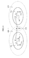
- Fig.11 is a schematic diagram showing the cell arrangement in accordance with the third embodiment of the present invention.
- the third embodiment of the present invention is provided to show examples of a base station and a mobile station, having the receiver/transmitter apparatuses in accordance with the first embodiment of the present invention, for use in the environment of the cell arrangement in the case where only one frequency is available.
- adjacent cells can be located overlapped with each other by expanding the coverage of the cell of the respective base station designed in accordance with the first embodiment as described above. Meanwhile, only two base stations are illustrated for the sake of explanation.
- the respective base stations 96n-1 and 96n serve to provide ordinary coverage 98n-1 and 98n and spreading coverage 100n-1 and 100n.
- the base stations 96n-1 and 96n perform conventional OFDM in the ordinary coverages 98n-1 and 98n in which the mobile stations 102a and 102c maintain communication with the base stations 96n-1 and 96n on the basis of the conventional OFDM.
- the mobile station 102a located in the ordinary coverage 98n-1 and the mobile station 102c located in the ordinary coverage 98n can be in communication with the base stations 96n-1 and 96n to perform a higher speed data exchange than the mobile station 102b located in the spreading coverage 100n-1 and the spreading coverage 100n.
- the mobile station 102b is located in both the spreading coverage 100n-1 of the base station 96n-1 and the spreading coverage 100n of the base station 96n. In other words, the mobile station 102b can effectively receive signals from both the base station 96n-1 and the base station 96n.
- the base station 96n-1 and the base station 96n share an identical frequency but make use of different patterns for spectrum spreading and inverse spectrum spreading in order to make it possible to discriminate the signals transmitted by the base station 96n-1 from the signals transmitted by the base station 96n.
- the third embodiment of the present invention it is possible to avoid the interference associated when expanding the coverage of the cell even if adjacent cells share an identical frequency. Also, in accordance with the third embodiment of the present invention, it is possible to implement a handover system which is reliable even if a small number of frequencies are available.
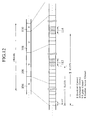
- Fig.12 is a schematic diagram showing an exemplary configuration of the burst frame in accordance with the third embodiment of the present invention.
- the burst frame in accordance with the third embodiment is substantially same as illustrated in Fig.3 showing a burst frame for the TDMA system in which time slots are allocated to the respective channels by timely division for multiplexing.
- the burst frame in accordance with the third embodiment consists of a broadcast channel 104 through which common information is broadcasted from a base station to all the mobile stations linked to the base station, a downlink channel 106 through which information items exclusive to the respective mobile stations are transfered from the base station to the individual mobile stations, an uplink channel 108 through which information items are transfered from the respective mobile stations to the base station, and a random access channel 110 through which a mobile station can transfer a request for allocation of wireless resources to the base station.
- the respective channels 104, 106, 108 and 110 are composed of a plurality of slots respectively.
- the coverage of the cell of the base station can be expanded by transmitting spectrum spread OFDM signals through the downlink channel 106 and the uplink channel 108 in order not to affect the concurrent conventional OFDM transmission.
- the slots 112 in the downlink channel 106 and the slots 114 in the uplink channel 108 are allocated to the transmission of the spectrum spread OFDM signals.
- the slots 112 and 114 as seen from the mobile stations 102a and 102c located in the ordinary coverage 98n-1 and 98n are simply neglected in the same manner as other slots allocated to other mobile stations. For this reason, the concurrent conventional OFDM transmission is not affected by the spectrum spread OFDM signals.
- the mobile station 102b located in the spreading coverage 100n-1 and 100n inverse spectrum spreads the signals as transmitted through the slots 112 and 114 by the use of the pattern identical to the pattern having used for spectrum spreading the same signals in the base stations 96n-1 and 96n. Because of this, the mobile station 102b can reproduce the signals as transmitted through the slots 112 and 114.
- the base station has to provide for the mobile station 102b located in the spreading coverage 100n-1 and 100n with a broadcast channel, a downlink channel through which information items exclusive to the mobile stations are transfered from the base station, an uplink channel 108 through which information items are transfered from the mobile stations to the base station, and a random access channel 110 through which the mobile station can transfer a request for allocation of wireless resources to the base station.
- these signals shall not affect the concurrent conventional OFDM transmission.
- the broadcast channel, the downlink channel, the uplink channel and the random access channel for the mobile station 102b are provided within the slots 112 in the downlink channel 106 and the slots 114 in the uplink channel 108.
- the spectrum spread OFDM signals are transmitted through the downlink channel 106 and the uplink channel 108 which are user channels, it is generally not predetermined which slots are allocated to the spectrum spread OFDM signals .
- the number of the slots in the burst frame as illustrated in Fig.12 which are preceding the slots allocated to the spectrum spread OFDM signals is depending upon the case.
- the base station serves to transmit to the mobile stations located in the ordinary coverage 98n-1 and 98n, through the broadcast channel, information about the number I of the slots in the burst frame which are preceding the slots that are located in the downlink channel and allocated to the spectrum spread OFDM signals and the number II of the slots in the burst frame which are preceding the slots that are located in the uplink channel and allocated to the spectrum spread OFDM signals, so that even when the mobile station transits to the spreading coverage, the burst frame synchronization is easily established.
- a mobile station located in an ordinary coverage is provided with allocation of slots other than the slots 112 and 114.
- the mobile station transits from the ordinary coverage to a spreading coverage, the mobile station can no longer reproduce information from the conventional OFDM signals.
- the inverse spectrum spreading circuit 142 of the receiver apparatus 10b serves to switch the inverse spreading pattern among from a plurality of predetermined patterns to search the inverse spreading pattern, that is identical to the spreading pattern having been used in the transmitter apparatus 10a, for inverse spreading the received signals and to detect the positions of the slots 112 and 114.
- the inverse spectrum spreading circuit 142 then retrieves necessary data items from the slots 112 and 114.
- the data items as retrieved are combined to form a burst frame for the TDMA system as illustrated in Fig.3 in which time slots are allocated to the respective channels by timely division for multiplexing.
- the burst frame formed by the slots 112 and 114 in combination is composed of a broadcast channel 104 through which common information is broadcasted from a base station to all the mobile stations linked to the base station, a downlink channel 106 through which information items exclusive to the respective mobile stations are transfered from the base station to the individual mobile stations, an uplink channel 108 through which information items are transfered from the respective mobile stations to the base station, and a random access channel 110 through which a mobile station can transfer a request for allocation of wireless resources to the base station.
- the respective channel 104, 106, 108 and 110 are composed of a plurality of slots. Namely, individual channels independent from the ordinary coverage are implemented in the spreading coverage in which the wireless resources of the spreading coverage are allocated.
- the base station serves to transmit to the mobile stations located in the spreading coverage 100n-1 and 100n information about the number I of the slots in the burst frame which are preceding the slots that are located in the downlink channel and allocated to the spectrum spread OFDM signals and the number II of the slots in the burst frame which are preceding the slots that are located in the uplink channel and allocated to the spectrum spread OFDM signals, so that the burst frame synchronization is easily established.
- the configuration as described above is effective particularly when it is preferred to minimize the modification of the existing system.
- the coverage of the cell of the base station can be expanded by transmitting spectrum spread OFDM signals in order not to affect the concurrent conventional OFDM transmission.
- the fourth embodiment is provided to show examples of the transmitter apparatus and the receiver apparatus in accordance with the first or third embodiment of the present invention, in which adaptive array antennas are used.
- the intelligent antenna technique is effective to improve the utilization of channels as taught in the above described references, i.e., "Intelligent Antenna Technology", Communications Society Conference Vol.1, TB-5-1, 1999, "Studies of Zone Generation Algorithm in Adaptive Variable Zone Structure System", Institute of Electronics, Information and Communication Engineers, B-5-204, 1998 and “Studies of Adaptive Variable Zone Structure System Implemented with a Directional Antenna in a Base Station", Communications Society Conference, B-5-81, 1998.
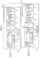
- Fig.13 is a block diagram showing the configuration of the antenna system for signal reception in accordance with the fourth embodiment of the present invention.
- the antenna system for signal reception in accordance with the fourth embodiment is composed of a plurality of antenna elements 116-1, 116-2, 116-3, ⁇ and 116-k, and an antenna control unit 118 for taking control of the antenna elements 116.
- the antenna control unit 118 is connected to the receiver apparatus 10b.
- the antenna control unit 118 is composed of a plurality of the weighting units 120-1, 120-2, 120-3, ⁇ and 120-k, an integrating unit 122 for integrating the received signals of the antenna elements 116 respectively as weighted by means of the plurality of the weighting units 120, a weighting control unit 124 for taking control of the plurality of the weighting units 120 and an incoming wave direction estimation unit 126 for estimating the direction of incoming waves on the basis of the received signals of the antenna elements 116.
- the incoming wave direction estimation unit 126 receives the signals as received by the antenna elements 116 respectively, and estimates the direction of the incoming waves to be received on the basis of the reception levels of the respective signals.
- the estimation is performed in accordance with an incoming wave direction estimation algorithm, e.g., MUSIC, ESPRIT and so forth.
- the weighting control unit 124 then controls the weights assigned to the respective weighting units 120 on the basis of the result of the estimation.
- MUSIC Multiple Emitter Location and Signal Parameter Estimation", IEEE, Trans., Vol.AP-32, No.3, pp.276-280, Mar. 1986.
- ESPRIT is described in "ESPRIT-Estimation of Signal Parameters via Rotational Invariance Techniques", IEEE, Trans., Vol.AP-37, pp.984-995, July 1986.
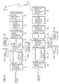
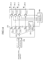
- Fig.14 is a block diagram showing the configuration of the antenna system for signal transmission in accordance with the fourth embodiment of the present invention.
- the antenna system for signal transmission in accordance with the fourth embodiment is composed of a plurality of antenna elements 128-1, 128-2, 128-3, and 128-1, and an antenna control unit 130 for taking control of the antenna elements 128.
- the antenna control unit 118 is connected to the transmitter apparatus 10a and the receiver apparatus 10b respectively.
- the antenna control unit 130 is composed of a plurality of weighting units 134-1, 134-2, 134-3, ⁇ and 134-k provided corresponding to the antenna elements 128 respectively, a splitter 136 for splitting the transmission signal as outputted from the transmitter apparatus 10a, a weighting control unit 138 for taking control of the plurality of the weighting units 134 and a plurality of circulators 132-1, 132-2, 132-3, ⁇ and 132-1 provided corresponding to the antenna elements 128 respectively for outputting the transmission signal as weighted by the corresponding weighting units 134 and outputting the received signals as input from the antenna elements 128.
- the splitter 136 serves to split the transmission signals as generated by the transmitter apparatus 10a, and output the transmission signals as split to the respective weighting units 134.
- the weighting control unit 138 serves to control the weight factors assigned to the respective weighting units 134 on the basis of the control signals from the receiver apparatus 10b
- the receiver apparatus 10b serves to generate the control signals on the basis of the incoming wave direction estimation unit 126 as illustrated in Fig.13.
- the receiver apparatus 10b controls the weighting control unit 138 in order to direct the beam in the same direction as the incoming waves to be received.
- the base station in accordance with the fourth embodiment of the present invention serves to transmit the spectrum spread OFDM signals to a mobile station remote from the base station.
- the signal transmission rate of the spectrum spread OFDM signals is lower than that of the conventional OFDM signal. In other words, the coverage of a cell is expanded by lowering the signal transmission rate.
- the weight factors of the adaptive array antenna are calculated on the basis of the conventional OFDM signals rather than the spectrum spread OFDM signals. Namely, in accordance with the fourth embodiment of the present invention, once the communication link is established, it is possible to make use of a conventional technique for controlling the weight factors of an adaptive array antenna.
- a mobile station located in an ordinary coverage is provided with allocation of slots other than the slots 112 and 114.
- the inverse spectrum spreading circuit 142 then initiates searching of the inverse spreading pattern, that is identical to the spreading pattern having been used in the transmitter apparatus 10a by switching the inverse spreading pattern among from a plurality of predetermined patterns for all the slots of the downlink channel 106 and the uplink channel 108 in order to detect the positions of the slots 112 and 114.
- the inverse spectrum spreading circuit 142 then retrieves necessary data items from the slots 112 and 114.
- the spectrum spread OFDM signals is not used for the purpose of exchanging user data unlike the third embodiment of the present invention.
- the spectrum spread OFDM signals is used only for the purpose of detecting the location of the mobile station having transited from the ordinary coverage to the spreading coverage. After completing the detection of the location of the mobile station having transited from the ordinary coverage to the spreading coverage, a beam of the adaptive array antenna is directed to the mobile station. By this process, the received signal level as required for establishing the conventional OFDM communication can be obtained.
- the mobile station is then capable of transfering a request for allocation of wireless resources to the base station through the random access channel 110 by means of the conventional OFDM signals.
- the mobile station having transited from the ordinary coverage to the spreading coverage can therefore resume the communication with the base station even in the spreading coverage in the same manner as in the ordinary coverage.
- the communication channel through the spectrum spread OFDM signals is released.
- the fourth embodiment of the present invention it is possible to solve the conventional problem of how to determine the initial position of a remote mobile station (the initial position determination) and to improve the utilization of the frequency resources by effectively controlling the weight factors given to an adaptive array antenna in the dynamic zone structure.
- a transmitter apparatus it is possible to realize a transmitter apparatus, a receiver apparatus and a base station provided with these apparatuses , in which it is possible to obtain information necessary for taking appropriate control of the antenna in order to direct a beam to the mobile station that is located in a remote position where a communication link can be established only by securing a necessary antenna gain through the adaptive array antenna directed to that mobile station.
Landscapes
- Engineering & Computer Science (AREA)
- Signal Processing (AREA)
- Computer Networks & Wireless Communication (AREA)
- Quality & Reliability (AREA)
- Mobile Radio Communication Systems (AREA)
- Transmitters (AREA)
Applications Claiming Priority (2)
| Application Number | Priority Date | Filing Date | Title |
|---|---|---|---|
| JP2000054028 | 2000-02-29 | ||
| JP2000054028 | 2000-02-29 |
Publications (2)
| Publication Number | Publication Date |
|---|---|
| EP1130840A2 true EP1130840A2 (fr) | 2001-09-05 |
| EP1130840A3 EP1130840A3 (fr) | 2003-11-19 |
Family
ID=18575335
Family Applications (1)
| Application Number | Title | Priority Date | Filing Date |
|---|---|---|---|
| EP01301710A Withdrawn EP1130840A3 (fr) | 2000-02-29 | 2001-02-26 | Modulation multiporteuse à étalage du spectre pour la communication cellulaire |
Country Status (2)
| Country | Link |
|---|---|
| US (1) | US6937558B2 (fr) |
| EP (1) | EP1130840A3 (fr) |
Cited By (7)
| Publication number | Priority date | Publication date | Assignee | Title |
|---|---|---|---|---|
| GB2394871A (en) * | 2002-11-01 | 2004-05-05 | Kddi Corp | Transmitter which selects between OFDM and MC-CDMA |
| WO2005062732A3 (fr) * | 2003-12-31 | 2006-11-09 | Agency Science Tech & Res | Systeme a multiplexage par repartition orthogonale de la frequence et par repartition en code a facteur d'etalement variable (vsf-ofcdm), recepteur utilise dans ce systeme et procede de traitement de signaux reçus dans ce systeme |
| WO2007010444A1 (fr) * | 2005-07-22 | 2007-01-25 | Nxp B.V. | Procede et dispositif d'exploitation de deux services sans fil |
| US7564906B2 (en) | 2004-02-17 | 2009-07-21 | Nokia Siemens Networks Oy | OFDM transceiver structure with time-domain scrambling |
| EP1443680A4 (fr) * | 2001-10-17 | 2010-01-13 | Univ Hokkaido Nat Univ Corp | Appareil radio et proc d de traitement de r seau adaptatif |
| US7961800B2 (en) | 2005-09-07 | 2011-06-14 | Nec Corporation | Adaptive radio/modulation apparatus, receiver apparatus, wireless communication system, and wireless communication method |
| EP1655918A3 (fr) * | 2004-11-03 | 2012-11-21 | Broadcom Corporation | Mode à faible débit et à longue portée pour des réseaux locals OFDM sans fil |
Families Citing this family (50)
| Publication number | Priority date | Publication date | Assignee | Title |
|---|---|---|---|---|
| KR100499472B1 (ko) * | 2000-12-06 | 2005-07-07 | 엘지전자 주식회사 | 순방향 링크에서의 적응 어레이를 이용한 빔포밍 시스템 |
| US7738438B2 (en) * | 2001-01-31 | 2010-06-15 | Sanyo Electric Co., Ltd. | Radio base system, channel allocation method and channel allocating program |
| US6940827B2 (en) * | 2001-03-09 | 2005-09-06 | Adaptix, Inc. | Communication system using OFDM for one direction and DSSS for another direction |
| US20100255890A1 (en) * | 2001-06-27 | 2010-10-07 | John Mikkelsen | Download management of audio and visual content, product method and system |
| US20100191602A1 (en) * | 2001-06-27 | 2010-07-29 | John Mikkelsen | Mobile banking and payment platform |
| US20100228630A1 (en) * | 2001-06-27 | 2010-09-09 | John Mikkelsen | Advertising methods and system with improved media delivery platform |
| CA2809894C (fr) | 2001-06-27 | 2017-12-12 | Skky Incorporated | Plate-forme de distribution de contenus de supports amelioree |
| JP4171261B2 (ja) | 2001-08-27 | 2008-10-22 | 松下電器産業株式会社 | 無線通信装置及び無線通信方法 |
| JP3727283B2 (ja) * | 2001-11-26 | 2005-12-14 | 松下電器産業株式会社 | 無線送信装置、無線受信装置及び無線送信方法 |
| US7173990B2 (en) * | 2001-12-27 | 2007-02-06 | Dsp Group Inc. | Joint equalization, soft-demapping and phase error correction in wireless system with receive diversity |
| US7209433B2 (en) * | 2002-01-07 | 2007-04-24 | Hitachi, Ltd. | Channel estimation and compensation techniques for use in frequency division multiplexed systems |
| US7099353B2 (en) * | 2002-01-30 | 2006-08-29 | Texas Instruments Incorporated | Orthogonal frequency division multiplexing system with superframe synchronization using correlation sequence |
| US7724637B2 (en) * | 2002-04-20 | 2010-05-25 | Conexant Systems, Inc. | Method and apparatus for controlled spectrum multi-carrier modulation |
| US7173991B2 (en) | 2002-06-17 | 2007-02-06 | Hitachi, Ltd. | Methods and apparatus for spectral filtering channel estimates |
| US7139340B2 (en) * | 2002-06-28 | 2006-11-21 | Hitachi, Ltd. | Robust OFDM carrier recovery methods and apparatus |
| CN100579309C (zh) * | 2002-08-23 | 2010-01-06 | 松下电器产业株式会社 | Ofdm-cdma发送装置和ofdm-cdma发送方法 |
| US7298275B2 (en) * | 2002-09-27 | 2007-11-20 | Rockwell Automation Technologies, Inc. | Machine associating method and apparatus |
| US7272456B2 (en) * | 2003-01-24 | 2007-09-18 | Rockwell Automation Technologies, Inc. | Position based machine control in an industrial automation environment |
| US20040166881A1 (en) * | 2003-02-06 | 2004-08-26 | Farchmin David Walter | Phased array wireless location method and apparatus |
| US7043316B2 (en) * | 2003-02-14 | 2006-05-09 | Rockwell Automation Technologies Inc. | Location based programming and data management in an automated environment |
| JP2004363721A (ja) * | 2003-06-02 | 2004-12-24 | Matsushita Electric Ind Co Ltd | 無線通信システム及び無線通信方法 |
| US20050071498A1 (en) * | 2003-09-30 | 2005-03-31 | Farchmin David W. | Wireless location based automated components |
| US7315563B2 (en) * | 2003-12-03 | 2008-01-01 | Ut-Battelle Llc | Multicarrier orthogonal spread-spectrum (MOSS) data communications |
| CN1879426B (zh) | 2004-01-29 | 2010-06-23 | 桥扬科技有限公司 | 用于多载波、多小区无线通信网络的方法和装置 |
| WO2005074166A1 (fr) | 2004-01-29 | 2005-08-11 | Neocific, Inc. | Procedes et appareil de superpositon de signaux multi-porteuses et a spectre etale a sequence directe dans un systeme de transmission sans fil a bande large |
| WO2005081439A1 (fr) | 2004-02-13 | 2005-09-01 | Neocific, Inc. | Procedes et dispositif pour des systemes de communication a porteuses multiples comportant une transmission et une retroaction adaptatives |
| US7251535B2 (en) * | 2004-02-06 | 2007-07-31 | Rockwell Automation Technologies, Inc. | Location based diagnostics method and apparatus |
| US8645569B2 (en) * | 2004-03-12 | 2014-02-04 | Rockwell Automation Technologies, Inc. | Juxtaposition based machine addressing |
| US7386027B2 (en) * | 2004-03-31 | 2008-06-10 | Matsushita Electric Industrial Co., Ltd. | Methods and apparatus for generating and processing wideband signals having reduced discrete power spectral density components |
| EP1793517A4 (fr) * | 2004-08-24 | 2010-12-08 | Sharp Kk | Systeme de communication de donnees, recepteur et emetteur |
| US7804912B2 (en) * | 2004-09-23 | 2010-09-28 | Motorola, Inc. | Method and apparatus for encryption of over-the-air communications in a wireless communication system |
| JP4701964B2 (ja) * | 2005-09-27 | 2011-06-15 | 日本電気株式会社 | マルチユーザ受信装置 |
| KR100872420B1 (ko) * | 2005-12-29 | 2008-12-05 | 삼성전자주식회사 | 다중 홉 릴레이 방식을 사용하는 광대역 무선 접속 통신시스템에서 단말에게 투명성 있는 릴레이 서비스를제공하기 위한 장치 및 방법 |
| US7808886B2 (en) * | 2006-01-18 | 2010-10-05 | Freescale Semiconductor, Inc. | Pilot signal in an FDMA communication system |
| US20070195731A1 (en) * | 2006-02-21 | 2007-08-23 | Camp William O Jr | Methods, systems and computer program products for establishing a point-to-point communication connection |
| US7471621B2 (en) * | 2006-04-06 | 2008-12-30 | Motorola, Inc. | Method and apparatus for dynamic adjustment of orthogonal frequency-division multiplexing during congested conditions |
| US7903749B2 (en) | 2006-08-16 | 2011-03-08 | Harris Corporation | System and method for applying frequency domain spreading to multi-carrier communications signals |
| US7649951B2 (en) | 2006-08-16 | 2010-01-19 | Harris Corporation | System and method for communicating data using symbol-based randomized orthogonal frequency division multiplexing (OFDM) with applied frequency domain spreading |
| US7813433B2 (en) * | 2006-08-16 | 2010-10-12 | Harris Corporation | System and method for communicating data using symbol-based randomized orthogonal frequency division multiplexing (OFDM) with selected subcarriers turned on or off |
| US7751488B2 (en) * | 2006-08-16 | 2010-07-06 | Harris Corporation | System and method for communicating data using symbol-based randomized orthogonal frequency division multiplexing (OFDM) |
| US7860147B2 (en) * | 2006-08-16 | 2010-12-28 | Harris Corporation | Method of communicating and associated transmitter using coded orthogonal frequency division multiplexing (COFDM) |
| WO2008035428A1 (fr) * | 2006-09-21 | 2008-03-27 | Fujitsu Limited | Terminal de communication, et procédé de réception du signal |
| KR100956494B1 (ko) | 2007-06-14 | 2010-05-07 | 엘지전자 주식회사 | 제어신호 전송 방법 |
| JP2009159579A (ja) * | 2007-12-25 | 2009-07-16 | Kochi Univ Of Technology | ホッピングパターン帰還型cdma通信方式 |
| JP5213586B2 (ja) * | 2008-08-25 | 2013-06-19 | 株式会社エヌ・ティ・ティ・ドコモ | ユーザ装置及び基地局装置並びに通信制御方法 |
| CN102246447A (zh) | 2008-12-10 | 2011-11-16 | 松下电器产业株式会社 | 无线通信终端装置、无线通信基站装置及信号扩频方法 |
| JP4990343B2 (ja) * | 2009-12-03 | 2012-08-01 | 株式会社エヌ・ティ・ティ・ドコモ | 無線通信システム及び無線通信方法 |
| JP4553409B1 (ja) * | 2010-02-26 | 2010-09-29 | 公立大学法人高知工科大学 | 通信システムおよびその方法 |
| US8565209B2 (en) | 2011-09-09 | 2013-10-22 | Kochi University Of Technology | Communication apparatus, communication system, communication method and computer-readable storage medium |
| US10097321B2 (en) * | 2014-05-08 | 2018-10-09 | Qualcomm Incorporated | Cooperative techniques between lower-frequency carriers and millimeter-wave channels for discovery and synchronization and beamforming |
Family Cites Families (11)
| Publication number | Priority date | Publication date | Assignee | Title |
|---|---|---|---|---|
| JPH07245574A (ja) | 1994-03-07 | 1995-09-19 | Nippon Hoso Kyokai <Nhk> | ディジタル信号伝送方法 |
| JP3226455B2 (ja) | 1996-03-04 | 2001-11-05 | 三菱電機株式会社 | 無線通信路リンクアップシステム |
| US6016313A (en) * | 1996-11-07 | 2000-01-18 | Wavtrace, Inc. | System and method for broadband millimeter wave data communication |
| US5983101A (en) | 1996-11-26 | 1999-11-09 | Telefonaktiebolaget Lm Ericsson | Point to multipoint radio access system |
| JPH10210002A (ja) | 1997-01-17 | 1998-08-07 | Victor Co Of Japan Ltd | 移動通信方式 |
| WO1999004523A1 (fr) | 1997-07-15 | 1999-01-28 | Mitsubishi Denki Kabushiki Kaisha | Emetteur, recepteur et procede d'emission et de reception |
| US6108374A (en) * | 1997-08-25 | 2000-08-22 | Lucent Technologies, Inc. | System and method for measuring channel quality information |
| AU2848699A (en) * | 1998-03-30 | 1999-10-18 | Northern Telecom Limited | Adaptive modulation for cdma systems |
| US6621808B1 (en) * | 1999-08-13 | 2003-09-16 | International Business Machines Corporation | Adaptive power control based on a rake receiver configuration in wideband CDMA cellular systems (WCDMA) and methods of operation |
| JP2001055275A (ja) | 1999-08-18 | 2001-02-27 | Torque Seimitsu Kogyo Kk | 二液バッグ用中間止め具 |
| JP3631086B2 (ja) | 2000-02-23 | 2005-03-23 | 株式会社エヌ・ティ・ティ・ドコモ | マルチキャリアcdma無線伝送方法及び装置 |
-
2001
- 2001-02-26 US US09/791,795 patent/US6937558B2/en not_active Expired - Fee Related
- 2001-02-26 EP EP01301710A patent/EP1130840A3/fr not_active Withdrawn
Cited By (13)
| Publication number | Priority date | Publication date | Assignee | Title |
|---|---|---|---|---|
| EP1443680A4 (fr) * | 2001-10-17 | 2010-01-13 | Univ Hokkaido Nat Univ Corp | Appareil radio et proc d de traitement de r seau adaptatif |
| US7391715B2 (en) | 2002-11-01 | 2008-06-24 | Kddi Corporation | Transmitter device and transmitting method using OFDM and MC-CDMA |
| GB2394871A (en) * | 2002-11-01 | 2004-05-05 | Kddi Corp | Transmitter which selects between OFDM and MC-CDMA |
| US7715462B2 (en) | 2003-12-31 | 2010-05-11 | Agency For Science, Technology And Research | Variable spreading factor-orthogonal frequency and code division multiplexing (VSF-OFCDM) system, a receiver for use therein and a method of processing received signals in such a system |
| WO2005062732A3 (fr) * | 2003-12-31 | 2006-11-09 | Agency Science Tech & Res | Systeme a multiplexage par repartition orthogonale de la frequence et par repartition en code a facteur d'etalement variable (vsf-ofcdm), recepteur utilise dans ce systeme et procede de traitement de signaux reçus dans ce systeme |
| US7564906B2 (en) | 2004-02-17 | 2009-07-21 | Nokia Siemens Networks Oy | OFDM transceiver structure with time-domain scrambling |
| CN1918874B (zh) * | 2004-02-17 | 2010-09-29 | 诺基亚西门子网络公司 | 带有时域扰频的ofdm收发器结构 |
| EP1655918A3 (fr) * | 2004-11-03 | 2012-11-21 | Broadcom Corporation | Mode à faible débit et à longue portée pour des réseaux locals OFDM sans fil |
| US8363696B2 (en) | 2004-11-03 | 2013-01-29 | Broadcom Corporation | Low-rate long-range mode for OFDM wireless LAN |
| WO2007010444A1 (fr) * | 2005-07-22 | 2007-01-25 | Nxp B.V. | Procede et dispositif d'exploitation de deux services sans fil |
| US8451758B2 (en) | 2005-07-22 | 2013-05-28 | Entropic Communications, Inc. | Method and device for operating of two wireless services |
| US7961800B2 (en) | 2005-09-07 | 2011-06-14 | Nec Corporation | Adaptive radio/modulation apparatus, receiver apparatus, wireless communication system, and wireless communication method |
| CN101258701B (zh) * | 2005-09-07 | 2011-08-17 | 日本电气株式会社 | 自适应无线电/调制装置、接收器装置、无线通信系统和无线通信方法 |
Also Published As
| Publication number | Publication date |
|---|---|
| EP1130840A3 (fr) | 2003-11-19 |
| US6937558B2 (en) | 2005-08-30 |
| US20010021182A1 (en) | 2001-09-13 |
Similar Documents
| Publication | Publication Date | Title |
|---|---|---|
| US6937558B2 (en) | Transmitter apparatus and receiver apparatus and base station making use of orthogonal frequency division multiplexing and spectrum spreading | |
| US10826744B2 (en) | Preambles in OFDMA system | |
| JP4171261B2 (ja) | 無線通信装置及び無線通信方法 | |
| EP2790331B1 (fr) | Dispositif de transmission MIMO-OFDM et méthode de transmission MIMO-OFDM | |
| KR100915750B1 (ko) | 통신 방법 및 그것을 이용한 송신 장치와 수신장치 | |
| US7675841B2 (en) | Apparatus and method for generating a preamble sequence in an orthogonal frequency division multiplexing communication system | |
| US7069009B2 (en) | Apparatus and method for allocating resources of a virtual cell in an OFDM mobile communication system | |
| US8009549B2 (en) | Carrier allocation method in multi cell orthogonal frequency division multiple access system | |
| KR101614982B1 (ko) | 무선 통신 신호들 내의 제1 및 제2 프리앰블들의 사용 | |
| US20080151743A1 (en) | Radio Access System and Method Using Ofdm and Cdma for Broadband Data Transmission | |
| JP2001320346A (ja) | 直交周波数分割多重変調とスペクトル拡散を併用する送信装置、受信装置および基地局 | |
| JP4157443B2 (ja) | 送信方法、送信信号生成方法およびそれを用いた送信装置 | |
| JP2008072733A (ja) | 無線通信方法及び無線通信装置 | |
| KR20070114388A (ko) | 하향링크 채널용의 송신장치 및 송신방법 | |
| US20040208255A1 (en) | Wireless communication apparatus and wireless communication system | |
| KR100566273B1 (ko) | 주파수 도약 직교주파수분할다중화 시스템에서의 간섭회피 데이터 전송 방법 | |
| US20070191017A1 (en) | Apparatus and method for simultaneously receiving two neighboring frequency assignments in a cellular system | |
| KR20050110409A (ko) | 다중 안테나를 가진 통신 시스템의 채널 품질 지시자 채널전송 시스템 및 방법 |
Legal Events
| Date | Code | Title | Description |
|---|---|---|---|
| PUAI | Public reference made under article 153(3) epc to a published international application that has entered the european phase |
Free format text: ORIGINAL CODE: 0009012 |
|
| 17P | Request for examination filed |
Effective date: 20010321 |
|
| AK | Designated contracting states |
Kind code of ref document: A2 Designated state(s): AT BE CH CY DE DK ES FI FR GB GR IE IT LI LU MC NL PT SE TR |
|
| AX | Request for extension of the european patent |
Free format text: AL;LT;LV;MK;RO;SI |
|
| PUAL | Search report despatched |
Free format text: ORIGINAL CODE: 0009013 |
|
| RIC1 | Information provided on ipc code assigned before grant |
Ipc: 7H 04L 1/00 B Ipc: 7H 04B 7/06 B Ipc: 7H 04B 7/26 B Ipc: 7H 04L 5/02 A |
|
| AK | Designated contracting states |
Kind code of ref document: A3 Designated state(s): AT BE CH CY DE DK ES FI FR GB GR IE IT LI LU MC NL PT SE TR |
|
| AX | Request for extension of the european patent |
Extension state: AL LT LV MK RO SI |
|
| AKX | Designation fees paid |
Designated state(s): DE FR GB |
|
| 17Q | First examination report despatched |
Effective date: 20070726 |
|
| STAA | Information on the status of an ep patent application or granted ep patent |
Free format text: STATUS: THE APPLICATION IS DEEMED TO BE WITHDRAWN |
|
| 18D | Application deemed to be withdrawn |
Effective date: 20090901 |