EP1132206B1 - Procédé et appareil de marquage des objets de formes variés - Google Patents
Procédé et appareil de marquage des objets de formes variés Download PDFInfo
- Publication number
- EP1132206B1 EP1132206B1 EP01302050A EP01302050A EP1132206B1 EP 1132206 B1 EP1132206 B1 EP 1132206B1 EP 01302050 A EP01302050 A EP 01302050A EP 01302050 A EP01302050 A EP 01302050A EP 1132206 B1 EP1132206 B1 EP 1132206B1
- Authority
- EP
- European Patent Office
- Prior art keywords
- items
- ink
- item
- color
- conveyor
- Prior art date
- Legal status (The legal status is an assumption and is not a legal conclusion. Google has not performed a legal analysis and makes no representation as to the accuracy of the status listed.)
- Expired - Lifetime
Links
- 238000000034 method Methods 0.000 title claims description 20
- 238000007639 printing Methods 0.000 claims description 35
- 238000001035 drying Methods 0.000 claims description 11
- RYGMFSIKBFXOCR-UHFFFAOYSA-N Copper Chemical compound [Cu] RYGMFSIKBFXOCR-UHFFFAOYSA-N 0.000 claims description 10
- 229910052802 copper Inorganic materials 0.000 claims description 10
- 239000010949 copper Substances 0.000 claims description 10
- 238000012795 verification Methods 0.000 description 7
- 238000004806 packaging method and process Methods 0.000 description 4
- 101100408352 Drosophila melanogaster Plc21C gene Proteins 0.000 description 3
- 239000002184 metal Substances 0.000 description 3
- 229910052751 metal Inorganic materials 0.000 description 3
- 238000012546 transfer Methods 0.000 description 3
- 239000000203 mixture Substances 0.000 description 2
- 238000012360 testing method Methods 0.000 description 2
- 235000009508 confectionery Nutrition 0.000 description 1
- 238000010276 construction Methods 0.000 description 1
- 238000001723 curing Methods 0.000 description 1
- 230000001419 dependent effect Effects 0.000 description 1
- 230000000994 depressogenic effect Effects 0.000 description 1
- 238000013461 design Methods 0.000 description 1
- 238000012986 modification Methods 0.000 description 1
- 230000004048 modification Effects 0.000 description 1
- 238000007649 pad printing Methods 0.000 description 1
- 238000009877 rendering Methods 0.000 description 1
- 238000005096 rolling process Methods 0.000 description 1
- 238000007790 scraping Methods 0.000 description 1
- 229910001220 stainless steel Inorganic materials 0.000 description 1
- 239000010935 stainless steel Substances 0.000 description 1
Images




Classifications
-
- B—PERFORMING OPERATIONS; TRANSPORTING
- B41—PRINTING; LINING MACHINES; TYPEWRITERS; STAMPS
- B41F—PRINTING MACHINES OR PRESSES
- B41F17/00—Printing apparatus or machines of special types or for particular purposes, not otherwise provided for
- B41F17/001—Pad printing apparatus or machines
Definitions
- the present invention relates to the marking of copper pipe fittings, and more particularly to methods and apparatus for marking of an ink UPC bar code on differently-shaped copper pipe fittings.
- UPC bar code allows for quick scanning of the price and other information about the product at the retail store.
- UPC bar code allows for quick scanning of the price and other information about the product at the retail store.
- Cumens et al. disclose a process and device for applying and verifying marks on cylindrically-shaped objects.
- the products disclosed by Cumens et al. are cylindrical in nature and are transported through the process in a vertical position. Furthermore, the objects travel in a continuous, in-line motion during printing or marking. Such a design limits the applicability of the process to a particular shape of object and does not provide for drying, curing, or verification of the printing on the object.
- U.S. Patent No. 5,383,398 to Binnen discloses a process and device for pad printing multi-color images onto stationary objects.
- the Binnen device does not provide for curing, part handling, orientation, mark verification or other such desired operations.
- US3960073 discloses a method of marking containers or cups having a closed end, a cylindrical side wall and an open end. Each colour is cured (dried) before the next colour is applied.
- the available devices and/or methods do not provide for a versatile marking system that can print multi-color markings on a variety of differently-shaped and oriented objects. Therefore, there is a desire and need in industry to have such a versatile apparatus and method that allows marking and/or printing on a variety of differently-shaped and oriented objects.
- One aspect of the present invention is a method of marking a copper pipe fitting by orienting the fitting so that ink may be printed on the desired area of the item.
- the copper pipe fitting is fed to a printing station and ink of a first color is printed on the item and then dried.
- the ink is then cured by providing heat to the ink.
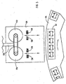
- Fig. 1 generally shows the apparatus 10 for marking items, packaging said items in a carton, and conveying said items to a desired location.
- marking system 10 of the present invention includes a bulk product tilt station 12, an infeed hopper 14, a feeder 15, a printing station 16, a curing tunnel 18, and a fill station 20.
- the bulk product tilt station 12, infeed hopper 14, and feeder 15 create a part orientation and feeding portion of marking system 10.
- the marking system 10 is controlled by a master PLC 21, which controls the timing and sequence of the steps for feeding and marking the items.
- the bulk product tilt station 12 receives the items to be printed in bulk, for example copper pipe fittings, and directs the items to the infeed hopper 14.
- Infeed hopper 14 in turn motivates the items onto a conveyor 22, which conveys the items to feeder 15.
- Feeder 15 includes a swivel chute 24, which directs the items into two bowl feeders 26 and 28.
- Bowl feeders 26 and 28 are each equipped with a low product sensor 30 that triggers the infeed hopper 14 to cycle and in turn causes the swivel chute to toggle (Fig. 2). Thus, sensor 30 insures that the bowl feeders are kept filled with product.
- Bowl feeders 26 and 28 are preferably stainless steel vibratory feeder bowls. The items are moved from bowl feeders 26 and 28 to four infeed conveyors 32, 33, 34, and 35. Bowl feeder 26 supplies infeed conveyors 32 and 33, while bowl feeder 28 supplies infeed conveyors 34 and 35. Infeed conveyors 32-35 are sized to contain the desired item to be marked.
- the feeder also includes four stack stoppers 38, 39, 40, and 41, which are made of a pneumatic cylinder construction, each having an 80 psi air line 44 connected thereto.
- Stack stoppers 38-41 hold back the stack or row of parts coming out of bowl feeders 26 and 28 to allow only one item at a time to enter into each of the infeed conveyors 32-35.
- the use of the stack stoppers minimizes jams and makes the entire operation more efficient.
- the items are conveyed from the feeder 15 to the printing station 16 by infeed conveyors 32-35.
- printing station 16 includes a servo-controlled robot 50.
- Robot 50 includes grippers and rotators 56 that grip each item individually and rotate it to the desired orientation.
- Robot 50 grabs the four items from the infeed conveyors 32-35 and places each item onto a product fixture 52 on a printing station turntable 54.
- the printing station has twelve product fixtures 52 and each holds four items.
- Turntable 54 likewise preferably includes twelve fixture hold down clamps 53 which hold the product fixtures 52 in place during the printing, drying, and verification processes.
- Turntable 54 is a rotary dial index table and travels in a clockwise direction when viewed from above. Also shown in Fig.
- sensors 69 are four product sensors 69, which ensure that four items are properly seated in product fixtures 52 after servo robot 50 places the items in product fixture 52 and before the printing station 16 goes through its cycle of printing the desired logo, print, or code on the items. If the items are not seated properly in product fixture 52, sensors 69 trigger PLC 21 which shuts down the operation of the printing station 16 and sends an alarm to the operator.
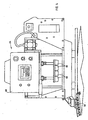
- Fig. 4 shows one of the two pad printers 64 of the printing station, the first of which is located clockwise to robot 50 when viewed from above.
- the pad printers 64 each have four printing pads 66 that lift ink off a cliché, described below, and transfer the ink to the item by pressing the pad downwardly onto the item held in product fixture 52.
- each pad printer supplies a single color that is different from the color supplied by the other pad printer.
- the product printers 64 are controlled by a PLC 68, which is programmed to ensure the proper timing and sequence of the printing step and is separate from PLC 21.
- Fig. 5 shows the cliché 130 of the printing station.
- the printing station preferably has two clichés, one for each printing stage/color.
- the cliché includes two ink cups 132, 134, each of which transfer ink into two receptacles 136 by moving across the receptacles and scraping the ink off of the area surrounding the receptacles.
- Pad printers 64 also include a shaft 135 with an end that connects to ink cups 132, 134.
- Shaft 135 is motivated to initiate forward and rearward ink cup travel, Pads 66 are positioned so they can be lowered onto said receptacles, after the receptacles are filled with ink, to pick up the ink in the receptacles and transfer it to the item which is to be printed.
- Adjacent turntable 54 are two drying units 60 and 61 (see Fig. 6), each having an expanded end 62 that is adjacent to the outer edge of turntable 54.
- Product fixtures 52 are positioned near the outer edge of turntable 54. Thus, once the item which sits in product fixture 52 is inked, the turntable is rotated so that the items are adjacent the dryer such that the ink may be dried.
- Fig. 7 shows the bar code scanners 70 that scan the inked bar code to verify that the bar code, or other marking, on each item is acceptable. Scanners 70 each scan one item on product fixture 52 and send a signal electronically to a PLC of whether the printed bar codes passed the verification scanning test or not. If the items do not pass the verification test, the turntable 54 bypasses the curing tunnel 18 and progresses to the rejector, as described below.
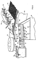
- Fig. 8 shows the positional relationship of turntable 54 to curing tunnel 18, and further shows a pick-and-place unit 71 and rejector 72 part of the system.
- the pneumatic pick-and-place unit 71 is used to off load the acceptable parts onto a conveyor 74 that leads to in curing tunnel 18.
- Pick-and-place unit 71 includes four robotic grippers 76 that pick the items out of a product fixture 52 and place the items on the curing tunnel conveyor 74 (see Fig. 8a).
- Rejector 2 includes four air-assisted reject blow off units 78 (Fig. 8).
- the air-assisted blow off units 78 are operated by four air lines 80 that each provide a stream of air to be forced against the item to dislodge the item from product fixture 52 and into a reject part bin 82.
- Rejector 72 also includes reject eject pins 84, which lift the items vertically up off of the product fixture 52. Eject pins 84 are also air actuated.
- the system also includes four through beam part detector sensors 90 for detecting that the fixture is empty to ensure that no product remains on the product fixture 52 as the dial is turned and the next cycle is started.
- Curing tunnel conveyor 82 is preferably made of metal cleat/mesh to minimize part rolling and preferably travels at 74 inches per minute through the curing tunnel.
- Curing tunnel 18 is preferably a confectionery oven, which is used to cure the ink onto the parts at a temperature of 230°C (450° F) for one minute.
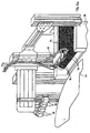
- Fig. 9 Another view of the curing tunnel 18 and its exit 100 are shown in Fig. 9.
- a plurality of passageways 102 which are defined by metal walls 104.
- a conveyor 106 Directly below exit 100 is a conveyor 106, which is driven by an electric DC drive motor 108.
- Conveyor 106 has two separate conveyor belts 106' and 106" at an angle, preferably both 45° with respect to horizontal and therefore 90° with respect to each other in a "V" shape.
- conveyor 110 At the end of conveyor 106, and slightly below conveyor 106, is another conveyor 110 which has a horizontal orientation.
- conveyor 110 is actuated by an electric DC drive motor 112.
- Adjacent conveyor 110 is a part-detect-through-beam sensor 114, which is used for counting parts that pass on conveyor 110.
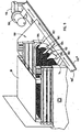
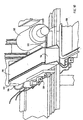
- a part hold back chute 116 which is shown in Fig. 10 in the "fill" position, thus allowing parts to drop into a box 118.
- Part hold back chute 116 is actuated by a pneumatic actuator 120 that, when the box count is reached, sensor 114 triggers a PLC that rotates part hold back chute 116 upwardly to a vertical position to hold back parts on the conveyor 110 until the full box 118 can be moved forward and an empty box is positioned in front of conveyor 110.
- Conveyor 110 also includes railing guides 122 to keep the items from falling off of conveyor 110.
- the items to be marked are dumped in bulk into the bulk product tilt station 12, which channels the items into infeed hopper 14.
- the items are conveyed to feeder 15 by conveyor 22, where the items are channeled through swivel chute 24 into bowl feeders 26 and 28.
- the items are motivated into the infeed conveyors 32-35, one at a time.
- Stack stoppers 38-41 prevent jamming by controlling the number of items that load into infeed conveyors 32-35 at a given time.
- the individual items are fed along infeed conveyors 32-35 to the printing station 16.
- the items are lifted from the conveyor by the grippers 56 of the servo-controlled robot 50, which places and orients the items onto one of the product fixtures 52 on turntable 54.
- the items are placed in product fixture 52 and oriented by gripper and rotator 56. Hold down clamps 58 are depressed to insure that the fixtures remain secure on turntable 54.
- the items are rotated on turntable 54 to the first inking station 64.
- the ink cups 132, 134 are moved to supply ink to receptacles 135 and the pads 66 are pressed downwardly thereon to lift the ink from the receptacles.
- a first color preferably white when marking a bar code, is applied to the item by pressing the four pads 66 onto the four items held in fixture 52. Once the first color is applied, turntable 54 is then rotated in a clockwise direction so that the item, still in product fixture 52, is adjacent to first drying unit 60. Drying unit 60 is activated, thereby drying the first inked color on the item.
- turntable 54 is again rotated in a clockwise direction so that the item is moved to the second inking station 65.
- a second color preferably black when a bar code is being marked on the item, is applied over the first ink color in the same manner as described above for the first color. Once the second color is applied, turntable 54 is again rotated so that the item is adjacent the second drying unit 61 where the second coat of ink is dried.
- turntable 54 is again rotated to motivate the item to the scanners 70.
- Scanners 70 scan the inked bar codes, or other such markings, on the items for verification that the markings are readable. If the markings are acceptable, the turntable 54 is rotated so the items are adjacent conveyor 74 and the items are lifted by the pick and place unit 71, which grips each item, and places the item on conveyor 74 of the curing tunnel 18. If one or more items is found to be unacceptable by any of the scanners 70, turntable 54 is rotated, motivating the items to the rejector 72.
- the eject pins 78 are actuated, which lift the rejected items up off of the product fixture 52, and the air-assisted blow off units 84 are actuated by air lines 80.
- the air assisted blow off units 78 blow the items off of the product fixture 52 and into the reject part bin 82.
- the items that are not rejected are conveyed along conveyor 74 through curing tunnel 18, where the items are subjected to an oven-like atmosphere at 230°C (450° F).
- the above-described system provides a reliable marking system, especially with regard to UPC bar codes, and allows differently-shaped items to be marked using the same system. Furthermore, it provides a system whereby items made of compositions that have been traditionally very difficult to mark with ink, particularly wrought copper items such as pipe fittings, can be marked with ink.
Landscapes
- Auxiliary Devices For And Details Of Packaging Control (AREA)
- Specific Conveyance Elements (AREA)
- Ink Jet (AREA)
Claims (3)
- Procédé de marquage d'un raccord de tube en cuivre, comprenant les étapes suivantes :(a) on met en oeuvre un raccord de tube en cuivre sur lequel se trouve une zone à imprimer;(b) on oriente ledit raccord dans une position telle que de l'encre puisse être imprimée sur ladite zone souhaitée dudit raccord;(c) on déplace ledit raccord jusqu'à un poste d'impression (16);(d) on imprime une encre d'une première couleur sur ledit raccord, tandis que ledit raccord se trouve dans ledit poste d'impression;(e) on sèche ladite encre d'une première couleur dans ledit poste d'impression;(f) on durcit ladite encre en appliquant de la chaleur à ladite encre;(g) on imprime de l'encre d'une deuxième couleur sur ledit raccord tandis qu'il se trouve dans ledit poste d'impression, après l'étape de séchage de ladite encre de la première couleur; et(h) on sèche ladite encre d'une deuxième couleur dans ledit poste d'impression, après l'étape d'impression de l'encre d'une deuxième couleur.
- Procédé selon la revendication 1 dans lequel ladite encre d'une première couleur et ladite encre d'une deuxième couleur sont imprimées pour former un code à barres.
- Procédé selon la revendication 1 dans lequel le procédé permet de marquer des raccords de tubes en cuivre ayant une variété de formes.
Applications Claiming Priority (2)
| Application Number | Priority Date | Filing Date | Title |
|---|---|---|---|
| US09/519,289 US6584894B1 (en) | 2000-03-06 | 2000-03-06 | Method and apparatus for marking items of varied shapes |
| US519289 | 2000-03-06 |
Publications (3)
| Publication Number | Publication Date |
|---|---|
| EP1132206A2 EP1132206A2 (fr) | 2001-09-12 |
| EP1132206A3 EP1132206A3 (fr) | 2001-11-28 |
| EP1132206B1 true EP1132206B1 (fr) | 2004-10-13 |
Family
ID=24067662
Family Applications (1)
| Application Number | Title | Priority Date | Filing Date |
|---|---|---|---|
| EP01302050A Expired - Lifetime EP1132206B1 (fr) | 2000-03-06 | 2001-03-06 | Procédé et appareil de marquage des objets de formes variés |
Country Status (5)
| Country | Link |
|---|---|
| US (1) | US6584894B1 (fr) |
| EP (1) | EP1132206B1 (fr) |
| CA (1) | CA2331109A1 (fr) |
| DE (1) | DE60106310T2 (fr) |
| ES (1) | ES2228755T3 (fr) |
Cited By (1)
| Publication number | Priority date | Publication date | Assignee | Title |
|---|---|---|---|---|
| US10882309B2 (en) | 2017-07-25 | 2021-01-05 | Illinois Tool Works Inc. | Printing system and method |
Families Citing this family (18)
| Publication number | Priority date | Publication date | Assignee | Title |
|---|---|---|---|---|
| US7168366B2 (en) * | 1998-04-03 | 2007-01-30 | Louviere Kent A | Apparatus and method for imprinting a vial |
| US7124681B2 (en) * | 1998-04-03 | 2006-10-24 | Louviere Kent A | Apparatus and method for imprinting a vial |
| US20010036871A1 (en) * | 2000-04-26 | 2001-11-01 | Lampinski Daniel B. | Method of applying high-fidelity color printed indicia to a golf ball |
| US7349130B2 (en) * | 2001-05-04 | 2008-03-25 | Geodigm Corporation | Automated scanning system and method |
| BE1014737A4 (nl) | 2002-03-29 | 2004-03-02 | Volder Laurent De | Werkwijze voor het bedrukken van doppen. |
| US7014284B2 (en) * | 2003-01-16 | 2006-03-21 | Morton William Bill | Ammunition having surface indicia and method of manufacture |
| US20080053320A1 (en) * | 2006-09-06 | 2008-03-06 | Illinois Tool Works Inc. | Pad printing of video targets for strain measurement |
| US8607699B2 (en) * | 2008-05-07 | 2013-12-17 | Illinois Tool Works Inc. | Rotating cliché pad printer |
| CN102529329B (zh) * | 2012-01-11 | 2014-07-02 | 张宗歧 | 一种全自动瓶盖烫色输送机 |
| US20140352562A1 (en) * | 2013-05-28 | 2014-12-04 | Willard Charles Raymond, JR. | Method and apparatus for digital pad printing |
| US11141995B2 (en) | 2015-12-28 | 2021-10-12 | The Procter & Gamble Company | Method and apparatus for applying a material onto articles with a pre-distorted transfer component |
| CN108430787A (zh) | 2015-12-28 | 2018-08-21 | 宝洁公司 | 利用在材料和粘合剂之间的固化程度差异将带有粘合剂的材料转移到制品上的方法 |
| US10940685B2 (en) | 2015-12-28 | 2021-03-09 | The Procter & Gamble Company | Method and apparatus for applying a material onto articles using a transfer component that deflects on both sides |
| US10682837B2 (en) | 2017-06-09 | 2020-06-16 | The Proctor & Gamble Company | Method and compositions for applying a material onto articles |
| WO2019099183A1 (fr) | 2017-11-17 | 2019-05-23 | The Procter & Gamble Company | Procédés pour appliquer un matériau sur des articles |
| CN111546762B (zh) | 2019-02-12 | 2022-04-19 | 宝洁公司 | 使用传送部件将材料施加到制品上的方法和设备 |
| WO2021183350A1 (fr) | 2020-03-09 | 2021-09-16 | The Procter & Gamble Company | Procédé et appareil permettant d'appliquer un matériau sur des articles à l'aide d'un composant de transfert |
| CN112659743A (zh) * | 2020-12-21 | 2021-04-16 | 安徽裕佳铝塑科技有限公司 | 一种带烘干功能的口红管图案印刷装置 |
Family Cites Families (40)
| Publication number | Priority date | Publication date | Assignee | Title |
|---|---|---|---|---|
| US3274927A (en) * | 1964-06-26 | 1966-09-27 | Owens Illinois Inc | Method and apparatus for decorating containers |
| US3641930A (en) | 1969-03-27 | 1972-02-15 | Sunkist Growers Inc | Apparatus for printing indicia on fruit |
| US4060031A (en) | 1969-08-02 | 1977-11-29 | Wilfried Philipp | Printing method and apparatus for performing the printing method |
| US3786746A (en) | 1971-10-06 | 1974-01-22 | Anchor Hocking Corp | High speed article coding machine |
| FR2206705A5 (fr) | 1972-11-10 | 1974-06-07 | Braud & Faucheux | |
| US3960073A (en) | 1975-03-10 | 1976-06-01 | American Can Company | Machine for decorating two-piece cans |
| US4047479A (en) | 1975-04-28 | 1977-09-13 | Kiwi Coders Corporation | High speed article coding machine |
| US4455328A (en) * | 1976-07-13 | 1984-06-19 | Metal Box Limited | Coating of articles |
| DE2552171A1 (de) * | 1975-11-21 | 1977-06-02 | Kurt G Hinterkopf | Maschine zum insbesondere mehrfarbigen bedrucken von hohlkoerperartigen werkstuecken |
| US4246840A (en) * | 1977-07-15 | 1981-01-27 | Izumi Denki Corporation | Printing machine for printing on a three-dimensional article |
| US4473008A (en) | 1983-09-20 | 1984-09-25 | Rca Corporation | Method for intaglio printing and selectively alterable inking plate therefor |
| CH663578A5 (de) | 1983-10-04 | 1987-12-31 | Madag Maschinen Apparatebau | Tampondruckmaschine zum bedrucken von werkstuecken mit druckfarbe. |
| US4530286A (en) | 1984-08-20 | 1985-07-23 | Rca Corporation | Intaglio printing plate for printing serial markings |
| JPH0657448B2 (ja) | 1984-12-04 | 1994-08-03 | マークテック株式会社 | 管内外面印字装置 |
| US4566382A (en) | 1985-02-13 | 1986-01-28 | Lakeland Rubber Stamp Company, Inc. | Line coder system for use on either side of conveyor line |
| US4709632A (en) | 1987-01-21 | 1987-12-01 | Rca Corporation | Selective intaglio inking device with removable cartridge |
| US4738199A (en) | 1987-01-30 | 1988-04-19 | Regina Chen | Multicolor transfer printing apparatus |
| US5023437A (en) | 1987-02-04 | 1991-06-11 | M. E. Cunningham Company | Bar code marking the surface of an object |
| US4813351A (en) * | 1987-09-18 | 1989-03-21 | Preco Industries, Inc. | Multiple color screen printing and curing apparatus |
| KR930000021B1 (ko) | 1988-07-20 | 1993-01-06 | 도오꾜오 덴끼 가부시끼가이샤 | 바아코우드 인쇄방법 및 그 장치 |
| US5018966A (en) | 1989-03-20 | 1991-05-28 | Hunter Engineering Company, Inc. | Strip drying or curing oven |
| IT1230808B (it) | 1989-08-09 | 1991-10-29 | Co E P T E Costruzioni Elettro | Nastro per la siglatura in particolare di cavi elettrici e simili e procedimento di siglatura. |
| GB2250952B (en) | 1990-11-28 | 1994-02-16 | Harry Thomason | Apparatus for applying printed matter to objects |
| US5239613A (en) * | 1991-10-09 | 1993-08-24 | American Screen Printing Equipment Company | Method and apparatus for controlling product curing heater |
| ATE123698T1 (de) | 1991-11-25 | 1995-06-15 | Georg Binnen | Mehrfarben-tampondruckmaschine. |
| US5226361A (en) | 1992-05-19 | 1993-07-13 | Micron Technology, Inc. | Integrated circuit marking and inspecting system |
| US5390964A (en) | 1992-10-01 | 1995-02-21 | Gray, Jr.; Lawrence C. | Labeled pipe fitting and method |
| JP3123626B2 (ja) | 1992-11-06 | 2001-01-15 | シオノギクオリカプス株式会社 | 固形製剤印刷装置 |
| JPH07237400A (ja) * | 1994-02-25 | 1995-09-12 | Pentel Kk | 装飾体の製造方法 |
| JPH0834868A (ja) * | 1994-05-18 | 1996-02-06 | Hayakawa Rubber Co Ltd | 重ね印刷された熱可塑性樹脂製品及び熱可塑性樹脂製品の重ね印刷方法 |
| US5520112A (en) * | 1994-12-02 | 1996-05-28 | Kimberly-Clark Corporation | Folded substrate, dual-sided printing process and substrates printed thereby |
| US5570632A (en) | 1995-03-23 | 1996-11-05 | The West Company, Incorporated | Apparatus and method for applying and verifying marks on the periphery of generally cylindrically-shaped objects |
| US5797493A (en) | 1995-10-27 | 1998-08-25 | Watson; Thomas J. | Plumbing fittings and method of packaging therefor |
| JP3477594B2 (ja) * | 1995-11-15 | 2003-12-10 | 株式会社テスコ | 空き缶回収におけるバーコード読取り装置 |
| US6283022B1 (en) * | 1997-10-17 | 2001-09-04 | Deco Patents, Inc. | Apparatus and method for direct rotary screen printing radiation curable compositions onto cylindrical articles |
| US6079326A (en) * | 1998-05-15 | 2000-06-27 | Carl Strutz & Co., Inc. | Method and apparatus for using workpiece registration to inline decorate and cure workpieces |
| US5921177A (en) * | 1998-06-04 | 1999-07-13 | John K. Shin | Pad printing machine |
| US6152030A (en) * | 1999-02-19 | 2000-11-28 | Fuqua; Rick Lee | Curing apparatus for a multi-color screen printing system |
| US6228169B1 (en) * | 1999-05-18 | 2001-05-08 | Nd Industries, Inc. | Method and apparatus for application of 360° coatings to articles |
| US6176181B1 (en) * | 1999-08-20 | 2001-01-23 | Paper Converting Machine Company | Deck configuration for a printing press |
-
2000
- 2000-03-06 US US09/519,289 patent/US6584894B1/en not_active Expired - Fee Related
-
2001
- 2001-01-16 CA CA002331109A patent/CA2331109A1/fr not_active Abandoned
- 2001-03-06 DE DE60106310T patent/DE60106310T2/de not_active Expired - Fee Related
- 2001-03-06 ES ES01302050T patent/ES2228755T3/es not_active Expired - Lifetime
- 2001-03-06 EP EP01302050A patent/EP1132206B1/fr not_active Expired - Lifetime
Cited By (1)
| Publication number | Priority date | Publication date | Assignee | Title |
|---|---|---|---|---|
| US10882309B2 (en) | 2017-07-25 | 2021-01-05 | Illinois Tool Works Inc. | Printing system and method |
Also Published As
| Publication number | Publication date |
|---|---|
| DE60106310T2 (de) | 2005-10-13 |
| DE60106310D1 (de) | 2004-11-18 |
| US6584894B1 (en) | 2003-07-01 |
| ES2228755T3 (es) | 2005-04-16 |
| EP1132206A3 (fr) | 2001-11-28 |
| CA2331109A1 (fr) | 2001-12-03 |
| EP1132206A2 (fr) | 2001-09-12 |
Similar Documents
| Publication | Publication Date | Title |
|---|---|---|
| US6584894B1 (en) | Method and apparatus for marking items of varied shapes | |
| US7354498B2 (en) | Pallet labeler system | |
| US6314876B1 (en) | Method and apparatus for transporting and processing a plurality of articles, and shaped article having serially registered component images | |
| US11542107B2 (en) | Method and assembly for transferring products | |
| CN216660637U (zh) | 用于利用至少一个标记元件对容器做标记的机器 | |
| US6345487B1 (en) | High quality control tablet filler device | |
| ATE334884T1 (de) | Vorrichtung und verfahren zum zuführen von mit ausgiesstüllen ausgestalteten beuteln zu einer füllmaschine | |
| US5878658A (en) | Apparatus and method for marking two sides of a pellet-shaped article | |
| US7168366B2 (en) | Apparatus and method for imprinting a vial | |
| KR100616018B1 (ko) | 다양한 형상의 제품을 마킹하는 방법 및 장치 | |
| JPH03162988A (ja) | ペレット形状の品物上に認印を付ける装置 | |
| US7124681B2 (en) | Apparatus and method for imprinting a vial | |
| JPH08295301A (ja) | 物品包装装置およびその方法 | |
| US5484047A (en) | Container decorating system | |
| CN220639275U (zh) | 一种pvc包装袋用印刷喷码装置 | |
| EP0870611B1 (fr) | Procédé pour imprimer des parties d'emballage | |
| US11858282B2 (en) | Systems and methods for marking tablet-shaped articles | |
| JP4003145B2 (ja) | 物品処理装置 | |
| US8196511B2 (en) | Method for overprinting already printed packages | |
| JPH08187835A (ja) | スクリーン印刷機 | |
| KR101913289B1 (ko) | 병 인쇄 모듈 | |
| JP2025123825A (ja) | パウチ・ボトル兼用グリッパ | |
| NL1014352C1 (nl) | Inrichting voor het opzetten van houders. | |
| JP2004537415A (ja) | スタック区間に印を付ける方法および装置 | |
| JPH0664730A (ja) | 物品整列供給装置 |
Legal Events
| Date | Code | Title | Description |
|---|---|---|---|
| PUAI | Public reference made under article 153(3) epc to a published international application that has entered the european phase |
Free format text: ORIGINAL CODE: 0009012 |
|
| AK | Designated contracting states |
Kind code of ref document: A2 Designated state(s): DE ES FR GB IT Kind code of ref document: A2 Designated state(s): AT BE CH CY DE DK ES FI FR GB GR IE IT LI LU MC NL PT SE TR |
|
| AX | Request for extension of the european patent |
Free format text: AL;LT;LV;MK;RO;SI |
|
| PUAL | Search report despatched |
Free format text: ORIGINAL CODE: 0009013 |
|
| AK | Designated contracting states |
Kind code of ref document: A3 Designated state(s): AT BE CH CY DE DK ES FI FR GB GR IE IT LI LU MC NL PT SE TR |
|
| AX | Request for extension of the european patent |
Free format text: AL;LT;LV;MK;RO;SI |
|
| 17P | Request for examination filed |
Effective date: 20020524 |
|
| AKX | Designation fees paid |
Free format text: DE ES FR GB IT |
|
| 17Q | First examination report despatched |
Effective date: 20021111 |
|
| GRAP | Despatch of communication of intention to grant a patent |
Free format text: ORIGINAL CODE: EPIDOSNIGR1 |
|
| GRAS | Grant fee paid |
Free format text: ORIGINAL CODE: EPIDOSNIGR3 |
|
| GRAA | (expected) grant |
Free format text: ORIGINAL CODE: 0009210 |
|
| AK | Designated contracting states |
Kind code of ref document: B1 Designated state(s): DE ES FR GB IT |
|
| REG | Reference to a national code |
Ref country code: GB Ref legal event code: FG4D |
|
| REF | Corresponds to: |
Ref document number: 60106310 Country of ref document: DE Date of ref document: 20041118 Kind code of ref document: P |
|
| PGFP | Annual fee paid to national office [announced via postgrant information from national office to epo] |
Ref country code: FR Payment date: 20050302 Year of fee payment: 5 |
|
| REG | Reference to a national code |
Ref country code: ES Ref legal event code: FG2A Ref document number: 2228755 Country of ref document: ES Kind code of ref document: T3 |
|
| PLBE | No opposition filed within time limit |
Free format text: ORIGINAL CODE: 0009261 |
|
| STAA | Information on the status of an ep patent application or granted ep patent |
Free format text: STATUS: NO OPPOSITION FILED WITHIN TIME LIMIT |
|
| ET | Fr: translation filed | ||
| 26N | No opposition filed |
Effective date: 20050714 |
|
| PGFP | Annual fee paid to national office [announced via postgrant information from national office to epo] |
Ref country code: ES Payment date: 20060321 Year of fee payment: 6 |
|
| PGFP | Annual fee paid to national office [announced via postgrant information from national office to epo] |
Ref country code: DE Payment date: 20060330 Year of fee payment: 6 |
|
| PGFP | Annual fee paid to national office [announced via postgrant information from national office to epo] |
Ref country code: IT Payment date: 20060331 Year of fee payment: 6 |
|
| GBPC | Gb: european patent ceased through non-payment of renewal fee |
Effective date: 20070306 |
|
| REG | Reference to a national code |
Ref country code: FR Ref legal event code: ST Effective date: 20071130 |
|
| PG25 | Lapsed in a contracting state [announced via postgrant information from national office to epo] |
Ref country code: DE Free format text: LAPSE BECAUSE OF NON-PAYMENT OF DUE FEES Effective date: 20071002 |
|
| PG25 | Lapsed in a contracting state [announced via postgrant information from national office to epo] |
Ref country code: GB Free format text: LAPSE BECAUSE OF NON-PAYMENT OF DUE FEES Effective date: 20070306 |
|
| REG | Reference to a national code |
Ref country code: ES Ref legal event code: FD2A Effective date: 20070307 |
|
| PG25 | Lapsed in a contracting state [announced via postgrant information from national office to epo] |
Ref country code: FR Free format text: LAPSE BECAUSE OF NON-PAYMENT OF DUE FEES Effective date: 20070402 Ref country code: ES Free format text: LAPSE BECAUSE OF NON-PAYMENT OF DUE FEES Effective date: 20070307 |
|
| PG25 | Lapsed in a contracting state [announced via postgrant information from national office to epo] |
Ref country code: FR Free format text: LAPSE BECAUSE OF NON-PAYMENT OF DUE FEES Effective date: 20060331 |
|
| PGFP | Annual fee paid to national office [announced via postgrant information from national office to epo] |
Ref country code: GB Payment date: 20060206 Year of fee payment: 6 |
|
| PG25 | Lapsed in a contracting state [announced via postgrant information from national office to epo] |
Ref country code: IT Free format text: LAPSE BECAUSE OF NON-PAYMENT OF DUE FEES Effective date: 20070306 |