EP1132290B2 - Lukendeckel - Google Patents
Lukendeckel Download PDFInfo
- Publication number
- EP1132290B2 EP1132290B2 EP01200858.7A EP01200858A EP1132290B2 EP 1132290 B2 EP1132290 B2 EP 1132290B2 EP 01200858 A EP01200858 A EP 01200858A EP 1132290 B2 EP1132290 B2 EP 1132290B2
- Authority
- EP
- European Patent Office
- Prior art keywords
- hatch cover
- plate
- cover according
- improved
- sliding element
- Prior art date
- Legal status (The legal status is an assumption and is not a legal conclusion. Google has not performed a legal analysis and makes no representation as to the accuracy of the status listed.)
- Expired - Lifetime
Links
- XLYOFNOQVPJJNP-UHFFFAOYSA-N water Substances O XLYOFNOQVPJJNP-UHFFFAOYSA-N 0.000 claims description 5
- 238000007789 sealing Methods 0.000 claims description 4
- 230000002093 peripheral effect Effects 0.000 claims description 3
- 125000006850 spacer group Chemical group 0.000 claims description 2
- 230000003014 reinforcing effect Effects 0.000 claims 1
- 240000008042 Zea mays Species 0.000 description 2
- 230000007423 decrease Effects 0.000 description 2
- 238000010276 construction Methods 0.000 description 1
- 238000006073 displacement reaction Methods 0.000 description 1
- 230000002787 reinforcement Effects 0.000 description 1
- 238000011144 upstream manufacturing Methods 0.000 description 1
Images


Classifications
-
- B—PERFORMING OPERATIONS; TRANSPORTING
- B63—SHIPS OR OTHER WATERBORNE VESSELS; RELATED EQUIPMENT
- B63B—SHIPS OR OTHER WATERBORNE VESSELS; EQUIPMENT FOR SHIPPING
- B63B19/00—Arrangements or adaptations of ports, doors, windows, port-holes, or other openings or covers
- B63B19/12—Hatches; Hatchways
- B63B19/14—Hatch covers
Definitions
- the present invention relates to an improved hatch panel, more specifically to a hatch panel as used primarily in inboard navigation vessels for closing the cargo space.
- a hood which consists of a hatch cover covering the cargo space and two corner pillars attached to the two opposite ends of this panel by means of rivets in mortises and in slits. Corners pillars rest on rails, being present in the corridor of passage of people.
- the hoods are constructed so that they can slide telescopically one below or above the other giving a set that is massive and occupies the corridor of passage of the workers. The disadvantages of such constructions by their expanses are difficult to manipulate.
- the opening giving access to the cargo space is widened as much as possible, so that the gangway next to this opening becomes very narrow.
- the passageway is limited to the legal minimum, so that the access opening to the cargo space remains maximum.
- the present invention relates to an improved hatch cover which solves the above-mentioned problem as well as others.
- the invention relates to an improved hatch panel which is constituted by at least two parts which are able to move relative to each other in the longitudinal direction of the hatch panel, although that the length of this hatch cover can be adapted to the distance separating the edges of the cargo compartment of a boat.
- one of the aforementioned parts of a hatch panel of this type is formed by a plate, while the other part is formed by a sliding element which is fixed on the aforementioned plate.
- a hatch cover of this type according to the invention is provided with two sliding elements which respectively have a downward folded edge, each sliding element being connected to the aforementioned plate by means of guiding means. on the one hand, and using adjustment means on the other hand.
- a hatch panel according to the invention will be made so that it rises in thickness towards the center and consequently has a cam, while the plate is profiled so that one obtains channels of water evacuation at regular intervals, the height of which gradually decreases from the cam of the hatch panel to the two ends of the latter.
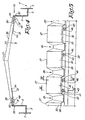
- a hatch cover 1 according to the invention is very schematically represented and is applied to the edges of the cargo compartment 2 - 3 of a boat 4, more specifically an inland waterway boat.
- each rim 2 - 3 of the goods compartment there is traditionally provided a channel 5, respectively 6 which are each formed by the bridge next to these flanges 2 - 3 of the cargo compartment and which, more specifically, are delimited, on the one hand by one of the aforementioned edges 2 - 3 of the cargo compartment and, on the other hand by the outer wall 7 of the boat 4.
- the hatch panel 1 in this embodiment, is constituted by a plate 8 which is provided, at one of its ends 9, with a folded edge 10 which is intended to be applied over the corresponding rim 3 of the cargo compartment, while the other end 11 of the hatch panel 1 is provided with a sliding element 12 with respect to the plate 8.
- the sliding element 12 is fixed below the plate 8 by means of guiding means which consist of one or more pins 13 which pass respectively, on the one hand a mortise 14 practiced in the plate 8 and, on the other hand, a slot 15 made in the sliding element 12.
- the sliding element 12 extends upstream of the end 11 of the plate 8 and is provided at the end 16 with a downwardly folded edge 17 which is intended to be applied over the rim. 2 of the goods compartment.
- the improved hatch panel is also provided with adjustment means which consist, on the one hand, of a series of projections 19 in which a hole 20 is formed and which are fixed on the upper side of the sliding element 12 and, on the other hand by a rim 21 which is part of the plate 8, a series of threaded holes 22 being provided in the flange 21, so that the holes 20 formed in the projections 19 and the threaded holes 22 formed in the rim 21 are arranged in a coaxial position, a bolt 23 being inserted through each projection 19, said bolt cooperating with a corresponding threaded hole 22.
- the bolt 23 is fixed axially with respect to the projection 19 by means of a locking washer 24 which is inserted into a peripheral groove formed in the bolt 23.
- the use of the improved hatch panel 1 according to the invention is very simple and is as indicated hereinafter.
- the bolts 23 are rotated so that, given that they are locked in the axial direction relative to their projection 19, a relative displacement is obtained between the plate 8 and the sliding element 12, until the folded edge 17 of the sliding element 12 and the folded edge 10 of the plate 8 abut against the edges 2 - 3 of the cargo compartment, so that the useful width of the passageways 5 and 6 becomes maximum.
- the bolts 23 of the tapped holes 22 made in the flange 21 are unscrewed; in this way, the folded edge 17 deviates from the rim 2 of the goods compartment; after which, it is possible to take the hatch panel 1 appropriately, for example by means of a vehicle intended for this purpose which is not shown in the figures.
- the hatch panel 1 may come to bear on the flanges 2 - 3 of the cargo compartment. so that the folded edges 17 and 10 are disposed accurately against these edges 2 - 3 of the goods compartment.
- FIG 3 there is shown an alternative embodiment of an improved hatch cover 1 according to the invention, wherein the plate 8 is provided at its two ends 9 and 11 with a sliding element 12 comprising a folded edge downwards. 17.
- the plate 8 has in this case a length which extends to a location just in front of the respective edges 2 - 3 of the cargo compartment, while the sliding elements 12 are applied with their folded edge 17 par- above the edges 2 - 3 of the goods compartment.
- hatch covers according to the figure 3 is similar to their use in the first embodiment, with the difference that in the case of the second embodiment, greater differences in the spacing between the two edges 2 - 3 of the cargo compartment, which come from the deformations of the boat 4, can be made up.
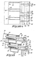
- FIGS. 4 to 11 represent a third embodiment of an improved hatch panel according to the invention.
- This variant of embodiment consists mainly of a plate 26 which rises in thickness towards the center and which consequently has a cam 27.
- the plate 26 is profiled so that gullies 28 are obtained for the evacuation water at regular intervals, the height of which gradually decreases from the cam 27 of the hatch panel 1 to the two ends 29 - 30 of the latter.
- a sliding element 31 - 32 oriented towards each of the ends 29 - 30 of the first mentioned, the element being provided with guide means which consist of a series of teeth 33 which are inserted in sliding in U-shaped guides 34 which are fixed below the plate 26, the two sliding elements 31 and 32 being intended to be applied on the edges 2 - 3 of the cargo compartment of the boat 4.
- the aforementioned sliding elements 31 and 32 extend in front of the plate 26, the edge 38, 39 respectively, of the sliding element 31 - 32 being folded downwards.
- adjustment means consist of a series of projections 41 in which holes 42 are provided which are arranged coaxially with the aforementioned threaded holes 37 made in the profiles. corresponding 35.
- each projection 41 is inserted a bolt 43 which cooperates with a corresponding threaded hole 37, the bolt 43, as in the previous embodiments, being fixed permanently axially with respect to the corresponding projection 41 to the using a locking washer 44 which is inserted into a peripheral groove formed in the bolt 43.
- sealing strips 47 are applied to the lower side of the profiles 35, respectively on the lower side of the plate 26, at the locations corresponding to the drainage channels 28. the water, said sealing strips 47 exerting pressure against the respective sliding elements 31 - 32.
- a spacer 48 is applied which also acts as a reinforcement section, the height of which is at least equal to the height of the folded edges 38 - 39.
- the aforementioned retractors 48 are intended to maintain the hatch panels 1, in the stacked state of the latter, at a sufficient distance, as shown in FIG. figure 11 , so that the folded edges 38 - 39 of the sliding elements 31 - 32 are not pinched, which could cause their deformation. Likewise, in this way, it is possible to easily switch the hatch covers.
Landscapes
- Chemical & Material Sciences (AREA)
- Engineering & Computer Science (AREA)
- Combustion & Propulsion (AREA)
- Mechanical Engineering (AREA)
- Ocean & Marine Engineering (AREA)
- Ship Loading And Unloading (AREA)
- Seal Device For Vehicle (AREA)
- Specific Sealing Or Ventilating Devices For Doors And Windows (AREA)
Claims (13)
- Perfektionierter Lukendeckel des Typs, der auf den Randleisten des Frachtraums eines Schiffes (4) angebracht werden kann, dadurch gekennzeichnet, dass er aus wenigstens zwei Teilen (8 - 12, 26 - 31 oder 32) besteht, die sich in Bezug zueinander in Längsrichtung des Lukendeckels (1) verschieben können, d.h., eine Platte (8, 26) und ein gleitendes Element (12, 31 oder 32) einzeln oder an jedem Ende (9 - 11; 29 - 30) der Platte, so dass die Länge dieses Lukendeckels (1) an die Abstand zwischen den Randleisten des Frachtraums des Schiffes angepasst werden kann und so dass die Länge dieses Lukendeckels (1) bis zu einem Abstand von wenigen Zentimetern vor den Randleisten des Frachtraums (4) des Schiffes (4) so angepasst werden kann, dass die Reduzierung der Breite des Gangs zwischen dem freien Ende des Lukendeckels und der Außenseite des Schiffes minimiert werden kann, und dadurch dass jedes gleitende Element (12, 31 oder 32) mit der Platte (8, 26) mit Hilfe von Führungsmitteln (13 - 15 bzw. 33 - 34) einerseits und mit Hilfe von Regulierungsmitteln (19 bis 24 bzw. 41 bis 44) andererseits verbunden ist.
- Perfektionierter Lukendeckel nach Anspruch 1, dadurch gekennzeichnet, dass die beiden Teile (8 -12, 26 - 31) mit einem nach unten umgebogenen Rand (10 - 17, 38 - 39) versehen sind.
- Perfektionierter Lukendeckel nach Anspruch 2, dadurch gekennzeichnet, dass er aus einer Platte (8) besteht, die an einem Ende mit einem nach unten umgebogenen Rand (10) versehen ist, während das andere Ende (11) der Platte (8) mit einem in Bezug auf diese Platte (8) gleitenden Element (12) versehen ist, das ebenfalls einen nach unten gebogenen Rand (17) aufweist.
- Perfektionierter Lukendeckel nach Anspruch 2, dadurch gekennzeichnet, dass der Lukendeckel (1) an beiden Enden (9 11, 29 - 30) der Platte (8) mit dem vorgenannten gleitenden Element (12, 31 - 32) versehen ist.
- Perfektionierter Lukendeckel nach einem der vorgenannten Ansprüche, dadurch gekennzeichnet, dass die Führungsmittel (13 - 15) durch einen oder mehrere Zapfen (13) gebildet sind, die jeweils einerseits durch ein Zapfenloch (14), angebracht in einem der Elemente, und andererseits durch einen Schlitz (15), angebracht in dem anderen Element, gehen.
- Perfektionierter Lukendeckel nach einem der vorhergehenden Ansprüche, dadurch gekennzeichnet, dass die Führungsmittel (33 - 34) durch Zähne (33) gebildet sind, die in die U-förmigen Führungen (34), die auf der Platte (26) bereitgestellt sind, eingeführt werden.
- Perfektionierter Lukendeckel nach einem der vorhergehenden Ansprüche, dadurch gekennzeichnet, dass die Regulierungsmittel (19 bis 23) einerseits aus einer Serie von Vorsprüngen (19), die an dem gleitenden Element (12) befestigt sind und jeweils mit einem Loch (20) versehen sind, und andererseits aus einer Randleiste (21), die Teil der Platte (8) ist, in der eine Serie von Gewindelöchern (22) bereitgestellt ist, bestehen, so dass die Löcher (20), die in den Vorsprüngen (19) angebracht sind, und die Gewindelöcher (22), die in der Randleiste (21) angebracht sind, in koaxialer Position angeordnet sind, wobei ein Bolzen (23) durch das vorgenannte Loch (20) eingeführt ist und dieser Bolzen (23) mit dem entsprechenden Gewindeloch (22) zusammenarbeitet.
- Perfektionierter Lukendeckel nach einem der vorhergehenden Ansprüche, dadurch gekennzeichnet, dass die Regulierungsmittel (41 bis 43) aus einer Serie von Vorsprüngen (41) bestehen, die auf dem gleitenden Element (31 - 32) befestigt sind, in denen Löcher (42) bereitgestellt sind, die in koaxialer Position zu den Gewindelöchern (37), die in Profilen (35) angebracht sind, die unter der Platte (26) auf Höhe der Enden (29 - 30) der Letzteren bereitgestellt sind, angeordnet sind, wobei ein Bolzen (43) in jeden Vorsprung (41) eingeführt wird, der mit einem entsprechenden Gewindeloch (37) zusammenarbeitet.
- Perfektionierter Lukendeckel nach Anspruch 7 oder 8, dadurch gekennzeichnet, dass der Bolzen (23, 43) mit Hilfe einer Blockierscheibe (24, 44), die in eine auf dem Bolzen (23, 43) angebrachte Umfangsrille eingesetzt ist, dauerhaft in axialer Richtung in Bezug auf den Vorsprung (19, 41) befestigt ist.
- Perfektionierter Lukendeckel nach Anspruch 8, dadurch gekennzeichnet, dass jedes Profil (35) mit einem Loch (36) versehen ist, und dass Vorsprünge (45) auf dem gleitenden Element (31 - 32) befestigt sind, in die ein Führungsstab (46) eingeführt ist, und der Führungsstab (46) in koaxialer Position zu dem vorgenannten Loch (36), das in dem Profil (35) angebracht ist, angeordnet ist.
- Perfektionierter Lukendeckel nach einem der vorhergehenden Ansprüche, dadurch gekennzeichnet, dass auf der gesamten Breite des Lukendeckels (1) auf der Unterseite der Profile (35) bzw. auf der Unterseite der Platte (8, 26) ein oder mehrere Dichtungsbänder (47) angebracht werden, und die Dichtungsbänder (47) einen Druck gegen die gleitenden Elemente (12, 31 - 32) ausüben.
- Perfektionierter Lukendeckel nach einem der vorhergehenden Ansprüche, dadurch gekennzeichnet, dass unter jedem gleitenden Element (12, 31 - 32) ein Abstandshalter (48) bzw. ein Verstärkungsprofil angebracht ist, deren Höhe wenigstens gleich der Höhe der umgebogenen Ränder (38 - 39) ist.
- Perfektionierter Lukendeckel nach einem der Ansprüche 2 bis 12, dadurch gekennzeichnet, dass die Platte (26) in ihrer Dicke zur Mitte hin zunimmt und folglich einen Kamm (27) aufweist, wobei die Platte (26) so profiliert ist, dass in regelmäßigen Abständen Wasserabfuhrrinnen (28) entstehen, deren Höhe allmählich vom Kamm (27) des Lukendeckels (1) bis zu den beiden Enden (29 - 30) des Letzteren abnimmt.
Priority Applications (1)
| Application Number | Priority Date | Filing Date | Title |
|---|---|---|---|
| DE60112493.6T DE60112493T3 (de) | 2000-03-08 | 2001-03-07 | Lukendeckel |
Applications Claiming Priority (2)
| Application Number | Priority Date | Filing Date | Title |
|---|---|---|---|
| BE20000179 | 2000-03-08 | ||
| BE2000/0179A BE1013343A3 (nl) | 2000-03-08 | 2000-03-08 | Verbeterd scheepsluik. |
Publications (3)
| Publication Number | Publication Date |
|---|---|
| EP1132290A1 EP1132290A1 (de) | 2001-09-12 |
| EP1132290B1 EP1132290B1 (de) | 2005-08-10 |
| EP1132290B2 true EP1132290B2 (de) | 2014-01-08 |
Family
ID=3896446
Family Applications (1)
| Application Number | Title | Priority Date | Filing Date |
|---|---|---|---|
| EP01200858.7A Expired - Lifetime EP1132290B2 (de) | 2000-03-08 | 2001-03-07 | Lukendeckel |
Country Status (3)
| Country | Link |
|---|---|
| EP (1) | EP1132290B2 (de) |
| BE (1) | BE1013343A3 (de) |
| DE (1) | DE60112493T3 (de) |
Families Citing this family (3)
| Publication number | Priority date | Publication date | Assignee | Title |
|---|---|---|---|---|
| BE1019405A3 (nl) * | 2011-06-29 | 2012-06-05 | Baeck Marine | Luikenkapsysteem met in lengte instelbare scheepsluiken. |
| NL2028378B1 (en) | 2021-06-03 | 2022-12-15 | Blommaert N V | Hatch, e.g. for an inland waterway cargo vessel, provided with photo-voltaic cells. |
| BE1029925B1 (nl) | 2021-11-16 | 2023-06-19 | Blommaert Nv | Schuifluikinrichting en verbeterde zijwand hiervoor alsook een werkwijze voor de vervaardiging |
Citations (2)
| Publication number | Priority date | Publication date | Assignee | Title |
|---|---|---|---|---|
| GB247024A (en) † | 1925-03-04 | 1926-02-11 | Charles William Alexander Tayl | A new or improved hatch locking appliance |
| GB369288A (en) † | 1930-11-24 | 1932-03-24 | Edward Elias Von Tell | Improvements in or relating to ships' hatchways |
Family Cites Families (5)
| Publication number | Priority date | Publication date | Assignee | Title |
|---|---|---|---|---|
| US2511007A (en) * | 1944-12-23 | 1950-06-13 | Prehn Henri | Cover for ship hatches |
| US2737919A (en) * | 1950-06-21 | 1956-03-13 | Waterman Steamship Corp | Hatch and sliding cover construction |
| CH348888A (de) * | 1956-12-13 | 1960-09-15 | Schweizerische Reederei Ag | Binnen-Güterschiff mit Lukendach |
| NL8003844A (nl) * | 1980-07-02 | 1982-02-01 | Peter J O Van Tilburg | Constructie van scheepsluiken van hetzij aluminium, hetzij staal, hetzij kunststof, of een combinatie daarvan met behulp van een speciaal daartoe geconstrueerde verstelbare mal. |
| BE899006A (nl) * | 1984-02-27 | 1984-06-18 | Blommaert Pv | Verbeterd kapluik voor schepen |
-
2000
- 2000-03-08 BE BE2000/0179A patent/BE1013343A3/nl not_active IP Right Cessation
-
2001
- 2001-03-07 DE DE60112493.6T patent/DE60112493T3/de not_active Expired - Lifetime
- 2001-03-07 EP EP01200858.7A patent/EP1132290B2/de not_active Expired - Lifetime
Patent Citations (2)
| Publication number | Priority date | Publication date | Assignee | Title |
|---|---|---|---|---|
| GB247024A (en) † | 1925-03-04 | 1926-02-11 | Charles William Alexander Tayl | A new or improved hatch locking appliance |
| GB369288A (en) † | 1930-11-24 | 1932-03-24 | Edward Elias Von Tell | Improvements in or relating to ships' hatchways |
Non-Patent Citations (4)
| Title |
|---|
| "Derkiena krijgt innovatieve luikenkap", SCHEEPVAARTKRANT, 13 October 1998 (1998-10-13) † |
| "Revolutionair plan : contract containerlijnvaart verdelen over meerdere schepen", DE BINNENVAARTKRANT, 8 October 1998 (1998-10-08), pages 17 † |
| "Rhine Vessels Inspection Regulations", CENTRAL COMMISSION FOR THE NAVIGATION ON THE RHINE, 1995, pages 75 - 76 † |
| "Speciaal luikenontwerp Derkiena levert extra gangboordbreedte op", SCHUTTEVAER, 3 February 2001 (2001-02-03), pages 1 - 2 † |
Also Published As
| Publication number | Publication date |
|---|---|
| DE60112493D1 (de) | 2005-09-15 |
| DE60112493T3 (de) | 2014-04-30 |
| EP1132290A1 (de) | 2001-09-12 |
| DE60112493T2 (de) | 2006-06-01 |
| BE1013343A3 (nl) | 2001-12-04 |
| EP1132290B1 (de) | 2005-08-10 |
Similar Documents
| Publication | Publication Date | Title |
|---|---|---|
| EP0224290B1 (de) | Bauart einer abdeckbaren Bedachung | |
| EP1641635B1 (de) | Vorrichtung zum spannen und festhalten einer leinwand | |
| EP1956177A1 (de) | Vorrichtung mit flexiblem Vorhang | |
| CA2100691A1 (fr) | Caisse d'emballage a claire-voie pourvue de moyens de gerbage et d'emboitage | |
| FR2485897A1 (fr) | Mallette | |
| EP1132290B2 (de) | Lukendeckel | |
| EP3802314B1 (de) | Druckkabinentür eines flugzeugs mit einer durch träger gebildeten struktur | |
| FR2520700A1 (fr) | Caisse de transport et/ou de stockage | |
| FR3006960A1 (fr) | Dispositif perfectionne de support d'un panneau de coffre de vehicule automobile. | |
| EP2159330B1 (de) | Schleusenrolltor und Schleuse mit einem derartigen Schleusentor | |
| EP0316379B1 (de) | Raumsparender vorhang zum verschliessen einer öffnung | |
| EP0799952A1 (de) | Vorrichtung zum Zusammenbau vorgefertigter Paneelen für eine Schwimmbadwand und dadurch hergestellte Schwimmbadwand | |
| FR2609488A1 (fr) | Banche extensible | |
| FR2558807A1 (fr) | Benne pour le stockage et le transport d'une charge | |
| FR2473990A1 (fr) | Cadre repliable, adaptable comme rebord lateral sur une palette | |
| FR2855500A1 (fr) | Caisse metallique repliable | |
| FR2781511A1 (fr) | Abri telescopique | |
| FR2935406A1 (fr) | Abri telescopique guide en partie haute | |
| EP0172770A1 (de) | Bedeckungsanlage für Räume oder Oberflächen, z.B. für Schwimmbäder | |
| FR2850090A1 (fr) | Toit ouvrant pour conteneur a chargement par le dessus | |
| FR3129653A1 (fr) | Plateforme flottante | |
| EP0446158A1 (de) | Tragwerkprofil aus Walzblech, Gebäudedecke aus solchen Profilen und Verfahren zu ihrer Montage | |
| CH583138A5 (en) | Air freight container - has lengthwise extruded girder at the top with slots for swing door hinges | |
| FR3091889A1 (fr) | Elément rigide pour un système de couverture de piscine | |
| FR2781188A1 (fr) | Coffre pour l'equipement de vehicules tels que camions, remorques ou semi-remorques, notamment pour le rangement et le transport de palettes de manutention |
Legal Events
| Date | Code | Title | Description |
|---|---|---|---|
| PUAI | Public reference made under article 153(3) epc to a published international application that has entered the european phase |
Free format text: ORIGINAL CODE: 0009012 |
|
| AK | Designated contracting states |
Kind code of ref document: A1 Designated state(s): CH DE FR LI LU NL Kind code of ref document: A1 Designated state(s): AT BE CH CY DE DK ES FI FR GB GR IE IT LI LU MC NL PT SE TR |
|
| AX | Request for extension of the european patent |
Free format text: AL;LT;LV;MK;RO;SI |
|
| 17P | Request for examination filed |
Effective date: 20020123 |
|
| AKX | Designation fees paid |
Free format text: CH DE FR LI LU NL |
|
| 17Q | First examination report despatched |
Effective date: 20031215 |
|
| GRAP | Despatch of communication of intention to grant a patent |
Free format text: ORIGINAL CODE: EPIDOSNIGR1 |
|
| GRAS | Grant fee paid |
Free format text: ORIGINAL CODE: EPIDOSNIGR3 |
|
| GRAA | (expected) grant |
Free format text: ORIGINAL CODE: 0009210 |
|
| AK | Designated contracting states |
Kind code of ref document: B1 Designated state(s): CH DE FR LI LU NL |
|
| REG | Reference to a national code |
Ref country code: CH Ref legal event code: EP |
|
| REF | Corresponds to: |
Ref document number: 60112493 Country of ref document: DE Date of ref document: 20050915 Kind code of ref document: P |
|
| PLBI | Opposition filed |
Free format text: ORIGINAL CODE: 0009260 |
|
| 26 | Opposition filed |
Opponent name: BAECK MARINE Effective date: 20060510 |
|
| PLAX | Notice of opposition and request to file observation + time limit sent |
Free format text: ORIGINAL CODE: EPIDOSNOBS2 |
|
| NLR1 | Nl: opposition has been filed with the epo |
Opponent name: BAECK MARINE |
|
| PLAF | Information modified related to communication of a notice of opposition and request to file observations + time limit |
Free format text: ORIGINAL CODE: EPIDOSCOBS2 |
|
| PLAF | Information modified related to communication of a notice of opposition and request to file observations + time limit |
Free format text: ORIGINAL CODE: EPIDOSCOBS2 |
|
| PLBB | Reply of patent proprietor to notice(s) of opposition received |
Free format text: ORIGINAL CODE: EPIDOSNOBS3 |
|
| PLAB | Opposition data, opponent's data or that of the opponent's representative modified |
Free format text: ORIGINAL CODE: 0009299OPPO |
|
| R26 | Opposition filed (corrected) |
Opponent name: BAECK MARINE Effective date: 20060510 |
|
| RDAF | Communication despatched that patent is revoked |
Free format text: ORIGINAL CODE: EPIDOSNREV1 |
|
| APBM | Appeal reference recorded |
Free format text: ORIGINAL CODE: EPIDOSNREFNO |
|
| APBP | Date of receipt of notice of appeal recorded |
Free format text: ORIGINAL CODE: EPIDOSNNOA2O |
|
| APAH | Appeal reference modified |
Free format text: ORIGINAL CODE: EPIDOSCREFNO |
|
| APBQ | Date of receipt of statement of grounds of appeal recorded |
Free format text: ORIGINAL CODE: EPIDOSNNOA3O |
|
| APBU | Appeal procedure closed |
Free format text: ORIGINAL CODE: EPIDOSNNOA9O |
|
| PUAH | Patent maintained in amended form |
Free format text: ORIGINAL CODE: 0009272 |
|
| STAA | Information on the status of an ep patent application or granted ep patent |
Free format text: STATUS: PATENT MAINTAINED AS AMENDED |
|
| 27A | Patent maintained in amended form |
Effective date: 20140108 |
|
| AK | Designated contracting states |
Kind code of ref document: B2 Designated state(s): CH DE FR LI LU NL |
|
| REG | Reference to a national code |
Ref country code: DE Ref legal event code: R102 Ref document number: 60112493 Country of ref document: DE |
|
| REG | Reference to a national code |
Ref country code: CH Ref legal event code: AELC |
|
| REG | Reference to a national code |
Ref country code: DE Ref legal event code: R102 Ref document number: 60112493 Country of ref document: DE Effective date: 20140108 |
|
| REG | Reference to a national code |
Ref country code: DE Ref legal event code: R082 Ref document number: 60112493 Country of ref document: DE Representative=s name: ADVOTEC. PATENT- UND RECHTSANWAELTE, DE |
|
| REG | Reference to a national code |
Ref country code: NL Ref legal event code: T3 |
|
| REG | Reference to a national code |
Ref country code: FR Ref legal event code: PLFP Year of fee payment: 16 |
|
| REG | Reference to a national code |
Ref country code: FR Ref legal event code: PLFP Year of fee payment: 17 |
|
| REG | Reference to a national code |
Ref country code: FR Ref legal event code: PLFP Year of fee payment: 18 |
|
| PGFP | Annual fee paid to national office [announced via postgrant information from national office to epo] |
Ref country code: NL Payment date: 20200326 Year of fee payment: 20 Ref country code: DE Payment date: 20200326 Year of fee payment: 20 |
|
| PGFP | Annual fee paid to national office [announced via postgrant information from national office to epo] |
Ref country code: CH Payment date: 20200325 Year of fee payment: 20 Ref country code: LU Payment date: 20200330 Year of fee payment: 20 |
|
| PGFP | Annual fee paid to national office [announced via postgrant information from national office to epo] |
Ref country code: FR Payment date: 20200327 Year of fee payment: 20 |
|
| REG | Reference to a national code |
Ref country code: DE Ref legal event code: R071 Ref document number: 60112493 Country of ref document: DE |
|
| REG | Reference to a national code |
Ref country code: NL Ref legal event code: MK Effective date: 20210306 |
|
| REG | Reference to a national code |
Ref country code: CH Ref legal event code: PL |