EP1132597B1 - Brennkraftmaschine - Google Patents
Brennkraftmaschine Download PDFInfo
- Publication number
- EP1132597B1 EP1132597B1 EP99951100A EP99951100A EP1132597B1 EP 1132597 B1 EP1132597 B1 EP 1132597B1 EP 99951100 A EP99951100 A EP 99951100A EP 99951100 A EP99951100 A EP 99951100A EP 1132597 B1 EP1132597 B1 EP 1132597B1
- Authority
- EP
- European Patent Office
- Prior art keywords
- combustion
- amount
- engine
- air
- fuel ratio
- Prior art date
- Legal status (The legal status is an assumption and is not a legal conclusion. Google has not performed a legal analysis and makes no representation as to the accuracy of the status listed.)
- Expired - Lifetime
Links
- 238000002485 combustion reaction Methods 0.000 title claims abstract description 213
- 239000004071 soot Substances 0.000 claims abstract description 83
- 238000002347 injection Methods 0.000 claims abstract description 61
- 239000007924 injection Substances 0.000 claims abstract description 61
- 238000004519 manufacturing process Methods 0.000 claims abstract description 29
- 230000006835 compression Effects 0.000 claims abstract description 28
- 238000007906 compression Methods 0.000 claims abstract description 28
- 230000003111 delayed effect Effects 0.000 claims abstract description 16
- 239000000446 fuel Substances 0.000 claims description 196
- 239000007789 gas Substances 0.000 claims description 101
- 239000002250 absorbent Substances 0.000 claims description 38
- 230000002745 absorbent Effects 0.000 claims description 38
- 239000011261 inert gas Substances 0.000 claims description 30
- 239000003054 catalyst Substances 0.000 claims description 19
- 230000003647 oxidation Effects 0.000 claims description 12
- 238000007254 oxidation reaction Methods 0.000 claims description 12
- 230000003134 recirculating effect Effects 0.000 claims 2
- 239000000779 smoke Substances 0.000 description 40
- 229930195733 hydrocarbon Natural products 0.000 description 25
- 150000002430 hydrocarbons Chemical class 0.000 description 25
- BASFCYQUMIYNBI-UHFFFAOYSA-N platinum Chemical compound [Pt] BASFCYQUMIYNBI-UHFFFAOYSA-N 0.000 description 23
- 230000006870 function Effects 0.000 description 22
- 238000010521 absorption reaction Methods 0.000 description 19
- 230000009471 action Effects 0.000 description 10
- 239000002243 precursor Substances 0.000 description 10
- 238000001816 cooling Methods 0.000 description 8
- 229910052697 platinum Inorganic materials 0.000 description 8
- 229910002651 NO3 Inorganic materials 0.000 description 7
- NHNBFGGVMKEFGY-UHFFFAOYSA-N Nitrate Chemical compound [O-][N+]([O-])=O NHNBFGGVMKEFGY-UHFFFAOYSA-N 0.000 description 7
- QVGXLLKOCUKJST-UHFFFAOYSA-N atomic oxygen Chemical compound [O] QVGXLLKOCUKJST-UHFFFAOYSA-N 0.000 description 7
- 229910052760 oxygen Inorganic materials 0.000 description 7
- 239000001301 oxygen Substances 0.000 description 7
- 238000002474 experimental method Methods 0.000 description 6
- 238000012545 processing Methods 0.000 description 5
- 230000007246 mechanism Effects 0.000 description 4
- 238000000034 method Methods 0.000 description 4
- 230000008569 process Effects 0.000 description 4
- QVQLCTNNEUAWMS-UHFFFAOYSA-N barium oxide Chemical compound [Ba]=O QVQLCTNNEUAWMS-UHFFFAOYSA-N 0.000 description 3
- 230000003197 catalytic effect Effects 0.000 description 3
- 230000008859 change Effects 0.000 description 3
- 150000002500 ions Chemical class 0.000 description 3
- 239000003513 alkali Substances 0.000 description 2
- 229910052783 alkali metal Inorganic materials 0.000 description 2
- 150000001340 alkali metals Chemical class 0.000 description 2
- 229910052788 barium Inorganic materials 0.000 description 2
- DSAJWYNOEDNPEQ-UHFFFAOYSA-N barium atom Chemical compound [Ba] DSAJWYNOEDNPEQ-UHFFFAOYSA-N 0.000 description 2
- 239000011575 calcium Substances 0.000 description 2
- 238000009841 combustion method Methods 0.000 description 2
- 239000000498 cooling water Substances 0.000 description 2
- 239000010970 precious metal Substances 0.000 description 2
- 229920006395 saturated elastomer Polymers 0.000 description 2
- 239000011734 sodium Substances 0.000 description 2
- 230000001629 suppression Effects 0.000 description 2
- 101100129496 Arabidopsis thaliana CYP711A1 gene Proteins 0.000 description 1
- OYPRJOBELJOOCE-UHFFFAOYSA-N Calcium Chemical compound [Ca] OYPRJOBELJOOCE-UHFFFAOYSA-N 0.000 description 1
- UGFAIRIUMAVXCW-UHFFFAOYSA-N Carbon monoxide Chemical compound [O+]#[C-] UGFAIRIUMAVXCW-UHFFFAOYSA-N 0.000 description 1
- 101100083446 Danio rerio plekhh1 gene Proteins 0.000 description 1
- DGAQECJNVWCQMB-PUAWFVPOSA-M Ilexoside XXIX Chemical compound C[C@@H]1CC[C@@]2(CC[C@@]3(C(=CC[C@H]4[C@]3(CC[C@@H]5[C@@]4(CC[C@@H](C5(C)C)OS(=O)(=O)[O-])C)C)[C@@H]2[C@]1(C)O)C)C(=O)O[C@H]6[C@@H]([C@H]([C@@H]([C@H](O6)CO)O)O)O.[Na+] DGAQECJNVWCQMB-PUAWFVPOSA-M 0.000 description 1
- WHXSMMKQMYFTQS-UHFFFAOYSA-N Lithium Chemical compound [Li] WHXSMMKQMYFTQS-UHFFFAOYSA-N 0.000 description 1
- ZLMJMSJWJFRBEC-UHFFFAOYSA-N Potassium Chemical compound [K] ZLMJMSJWJFRBEC-UHFFFAOYSA-N 0.000 description 1
- PNEYBMLMFCGWSK-UHFFFAOYSA-N aluminium oxide Inorganic materials [O-2].[O-2].[O-2].[Al+3].[Al+3] PNEYBMLMFCGWSK-UHFFFAOYSA-N 0.000 description 1
- 150000004945 aromatic hydrocarbons Chemical class 0.000 description 1
- 230000008901 benefit Effects 0.000 description 1
- 230000002457 bidirectional effect Effects 0.000 description 1
- 230000015572 biosynthetic process Effects 0.000 description 1
- 229910052792 caesium Inorganic materials 0.000 description 1
- TVFDJXOCXUVLDH-UHFFFAOYSA-N caesium atom Chemical compound [Cs] TVFDJXOCXUVLDH-UHFFFAOYSA-N 0.000 description 1
- 229910052791 calcium Inorganic materials 0.000 description 1
- 125000004432 carbon atom Chemical group C* 0.000 description 1
- 229910002091 carbon monoxide Inorganic materials 0.000 description 1
- 238000006243 chemical reaction Methods 0.000 description 1
- 238000007796 conventional method Methods 0.000 description 1
- 230000001186 cumulative effect Effects 0.000 description 1
- 230000000694 effects Effects 0.000 description 1
- 230000012447 hatching Effects 0.000 description 1
- 230000006872 improvement Effects 0.000 description 1
- 229910052746 lanthanum Inorganic materials 0.000 description 1
- FZLIPJUXYLNCLC-UHFFFAOYSA-N lanthanum atom Chemical compound [La] FZLIPJUXYLNCLC-UHFFFAOYSA-N 0.000 description 1
- 229910052744 lithium Inorganic materials 0.000 description 1
- 229910052700 potassium Inorganic materials 0.000 description 1
- 239000011591 potassium Substances 0.000 description 1
- 229910052761 rare earth metal Inorganic materials 0.000 description 1
- 150000002910 rare earth metals Chemical class 0.000 description 1
- 230000009467 reduction Effects 0.000 description 1
- 230000001105 regulatory effect Effects 0.000 description 1
- 238000011160 research Methods 0.000 description 1
- 229910052708 sodium Inorganic materials 0.000 description 1
- 239000007787 solid Substances 0.000 description 1
- 238000011144 upstream manufacturing Methods 0.000 description 1
- 229910052727 yttrium Inorganic materials 0.000 description 1
- VWQVUPCCIRVNHF-UHFFFAOYSA-N yttrium atom Chemical compound [Y] VWQVUPCCIRVNHF-UHFFFAOYSA-N 0.000 description 1
Images






Classifications
-
- F—MECHANICAL ENGINEERING; LIGHTING; HEATING; WEAPONS; BLASTING
- F02—COMBUSTION ENGINES; HOT-GAS OR COMBUSTION-PRODUCT ENGINE PLANTS
- F02D—CONTROLLING COMBUSTION ENGINES
- F02D41/00—Electrical control of supply of combustible mixture or its constituents
-
- F—MECHANICAL ENGINEERING; LIGHTING; HEATING; WEAPONS; BLASTING
- F02—COMBUSTION ENGINES; HOT-GAS OR COMBUSTION-PRODUCT ENGINE PLANTS
- F02D—CONTROLLING COMBUSTION ENGINES
- F02D41/00—Electrical control of supply of combustible mixture or its constituents
- F02D41/30—Controlling fuel injection
- F02D41/3011—Controlling fuel injection according to or using specific or several modes of combustion
- F02D41/3017—Controlling fuel injection according to or using specific or several modes of combustion characterised by the mode(s) being used
- F02D41/3035—Controlling fuel injection according to or using specific or several modes of combustion characterised by the mode(s) being used a mode being the premixed charge compression-ignition mode
-
- F—MECHANICAL ENGINEERING; LIGHTING; HEATING; WEAPONS; BLASTING
- F02—COMBUSTION ENGINES; HOT-GAS OR COMBUSTION-PRODUCT ENGINE PLANTS
- F02D—CONTROLLING COMBUSTION ENGINES
- F02D41/00—Electrical control of supply of combustible mixture or its constituents
- F02D41/0025—Controlling engines characterised by use of non-liquid fuels, pluralities of fuels, or non-fuel substances added to the combustible mixtures
- F02D41/0047—Controlling exhaust gas recirculation [EGR]
- F02D41/005—Controlling exhaust gas recirculation [EGR] according to engine operating conditions
- F02D41/0057—Specific combustion modes
-
- F—MECHANICAL ENGINEERING; LIGHTING; HEATING; WEAPONS; BLASTING
- F02—COMBUSTION ENGINES; HOT-GAS OR COMBUSTION-PRODUCT ENGINE PLANTS
- F02D—CONTROLLING COMBUSTION ENGINES
- F02D41/00—Electrical control of supply of combustible mixture or its constituents
- F02D41/30—Controlling fuel injection
- F02D41/3011—Controlling fuel injection according to or using specific or several modes of combustion
- F02D41/3064—Controlling fuel injection according to or using specific or several modes of combustion with special control during transition between modes
-
- F—MECHANICAL ENGINEERING; LIGHTING; HEATING; WEAPONS; BLASTING
- F02—COMBUSTION ENGINES; HOT-GAS OR COMBUSTION-PRODUCT ENGINE PLANTS
- F02D—CONTROLLING COMBUSTION ENGINES
- F02D41/00—Electrical control of supply of combustible mixture or its constituents
- F02D41/30—Controlling fuel injection
- F02D41/38—Controlling fuel injection of the high pressure type
- F02D41/40—Controlling fuel injection of the high pressure type with means for controlling injection timing or duration
- F02D41/401—Controlling injection timing
-
- F—MECHANICAL ENGINEERING; LIGHTING; HEATING; WEAPONS; BLASTING
- F02—COMBUSTION ENGINES; HOT-GAS OR COMBUSTION-PRODUCT ENGINE PLANTS
- F02M—SUPPLYING COMBUSTION ENGINES IN GENERAL WITH COMBUSTIBLE MIXTURES OR CONSTITUENTS THEREOF
- F02M26/00—Engine-pertinent apparatus for adding exhaust gases to combustion-air, main fuel or fuel-air mixture, e.g. by exhaust gas recirculation [EGR] systems
-
- F—MECHANICAL ENGINEERING; LIGHTING; HEATING; WEAPONS; BLASTING
- F02—COMBUSTION ENGINES; HOT-GAS OR COMBUSTION-PRODUCT ENGINE PLANTS
- F02M—SUPPLYING COMBUSTION ENGINES IN GENERAL WITH COMBUSTIBLE MIXTURES OR CONSTITUENTS THEREOF
- F02M26/00—Engine-pertinent apparatus for adding exhaust gases to combustion-air, main fuel or fuel-air mixture, e.g. by exhaust gas recirculation [EGR] systems
- F02M26/02—EGR systems specially adapted for supercharged engines
- F02M26/04—EGR systems specially adapted for supercharged engines with a single turbocharger
- F02M26/06—Low pressure loops, i.e. wherein recirculated exhaust gas is taken out from the exhaust downstream of the turbocharger turbine and reintroduced into the intake system upstream of the compressor
-
- F—MECHANICAL ENGINEERING; LIGHTING; HEATING; WEAPONS; BLASTING
- F02—COMBUSTION ENGINES; HOT-GAS OR COMBUSTION-PRODUCT ENGINE PLANTS
- F02D—CONTROLLING COMBUSTION ENGINES
- F02D41/00—Electrical control of supply of combustible mixture or its constituents
- F02D41/30—Controlling fuel injection
- F02D41/38—Controlling fuel injection of the high pressure type
- F02D2041/389—Controlling fuel injection of the high pressure type for injecting directly into the cylinder
-
- F—MECHANICAL ENGINEERING; LIGHTING; HEATING; WEAPONS; BLASTING
- F02—COMBUSTION ENGINES; HOT-GAS OR COMBUSTION-PRODUCT ENGINE PLANTS
- F02M—SUPPLYING COMBUSTION ENGINES IN GENERAL WITH COMBUSTIBLE MIXTURES OR CONSTITUENTS THEREOF
- F02M26/00—Engine-pertinent apparatus for adding exhaust gases to combustion-air, main fuel or fuel-air mixture, e.g. by exhaust gas recirculation [EGR] systems
- F02M26/13—Arrangement or layout of EGR passages, e.g. in relation to specific engine parts or for incorporation of accessories
- F02M26/22—Arrangement or layout of EGR passages, e.g. in relation to specific engine parts or for incorporation of accessories with coolers in the recirculation passage
- F02M26/23—Layout, e.g. schematics
-
- F—MECHANICAL ENGINEERING; LIGHTING; HEATING; WEAPONS; BLASTING
- F02—COMBUSTION ENGINES; HOT-GAS OR COMBUSTION-PRODUCT ENGINE PLANTS
- F02M—SUPPLYING COMBUSTION ENGINES IN GENERAL WITH COMBUSTIBLE MIXTURES OR CONSTITUENTS THEREOF
- F02M26/00—Engine-pertinent apparatus for adding exhaust gases to combustion-air, main fuel or fuel-air mixture, e.g. by exhaust gas recirculation [EGR] systems
- F02M26/13—Arrangement or layout of EGR passages, e.g. in relation to specific engine parts or for incorporation of accessories
- F02M26/22—Arrangement or layout of EGR passages, e.g. in relation to specific engine parts or for incorporation of accessories with coolers in the recirculation passage
- F02M26/33—Arrangement or layout of EGR passages, e.g. in relation to specific engine parts or for incorporation of accessories with coolers in the recirculation passage controlling the temperature of the recirculated gases
-
- Y—GENERAL TAGGING OF NEW TECHNOLOGICAL DEVELOPMENTS; GENERAL TAGGING OF CROSS-SECTIONAL TECHNOLOGIES SPANNING OVER SEVERAL SECTIONS OF THE IPC; TECHNICAL SUBJECTS COVERED BY FORMER USPC CROSS-REFERENCE ART COLLECTIONS [XRACs] AND DIGESTS
- Y02—TECHNOLOGIES OR APPLICATIONS FOR MITIGATION OR ADAPTATION AGAINST CLIMATE CHANGE
- Y02T—CLIMATE CHANGE MITIGATION TECHNOLOGIES RELATED TO TRANSPORTATION
- Y02T10/00—Road transport of goods or passengers
- Y02T10/10—Internal combustion engine [ICE] based vehicles
- Y02T10/12—Improving ICE efficiencies
-
- Y—GENERAL TAGGING OF NEW TECHNOLOGICAL DEVELOPMENTS; GENERAL TAGGING OF CROSS-SECTIONAL TECHNOLOGIES SPANNING OVER SEVERAL SECTIONS OF THE IPC; TECHNICAL SUBJECTS COVERED BY FORMER USPC CROSS-REFERENCE ART COLLECTIONS [XRACs] AND DIGESTS
- Y02—TECHNOLOGIES OR APPLICATIONS FOR MITIGATION OR ADAPTATION AGAINST CLIMATE CHANGE
- Y02T—CLIMATE CHANGE MITIGATION TECHNOLOGIES RELATED TO TRANSPORTATION
- Y02T10/00—Road transport of goods or passengers
- Y02T10/10—Internal combustion engine [ICE] based vehicles
- Y02T10/40—Engine management systems
Definitions
- the present invention relates to an internal combustion engine.
- the production of NO x has been suppressed by connecting the engine exhaust passage and the engine intake passage by an exhaust gas recirculation (EGR) passage so as to cause the exhaust gas, that is, the EGR gas, to recirculate in the engine intake passage through the EGR passage.
- EGR exhaust gas recirculation
- the EGR gas has a relatively high specific heat and therefore can absorb a large amount of heat, so the larger the amount of EGR gas, that is, the higher the EGR rate (amount of EGR gas/(amount of EGR gas + amount of intake air), the lower the combustion temperature in the combustion chamber.
- the EGR rate amount of EGR gas/(amount of EGR gas + amount of intake air
- the EGR rate was set within a range not exceeding the maximum allowable limit.
- the maximum allowable limit of the EGR rate differed considerably according to the type of the engine and the fuel, but was from 30 percent to 50 percent or so. Accordingly, in conventional diesel engines, the EGR rate was suppressed to 30 percent to 50 percent at a maximum.
- the EGR rate must be made at least about 55 percent.
- the EGR rate can be made at least about 55 percent when the amount of suction air is relatively small. That is, this new combustion is not possible when the amount of suction air exceeds a certain level. Therefore, when the amount of suction air exceeds a certain level, it is necessary to switch to the conventionally performed combustion. In this case, if the EGR rate is lowered to switch to the conventionally performed combustion, the EGR rate will pass the range of the EGR rate where the amount of smoke produced peaks, so a large amount of smoke will be produced.
- document EP 0 905 361 A2 relates to a combustion control system for a diesel engine provided with a fuel injection system comprising a control unit.
- the control unit controls the ignition timing to generally coincide with or be retarded relative to a fuel injection timing, regulating an ignition delay period to be longer than a fuel injection period in a predetermined engine operation region, thereby effectively accomplishing so called low temperature premix combustion.
- the fuel injection timing is retarded to the top dead center of the piston so as to increase the ignition delay period in the low engine speed and though the engine operating range in which an EGR is made at a high EGR rate.
- An object of the present invention is to provide an internal combustion engine capable of suppressing the generation of smoke when switching between new combustion and the conventionally performed combustion.
- an internal combustion engine in which an amount of production of soot gradually increases and peaks, when an amount of inert gas in a combustion chamber increases and in which a further increase of the amount of inert gas in the combustion chamber results in a temperature of fuel and surrounding gas in the combustion chamber becoming lower than a temperature of production of soot and therefore almost no production of soot any longer, the engine comprising switching means for selectively switching between a first combustion where the amount of inert gas in the combustion chamber is higher than the amount of inert gas where the amount of production of soot peaks and where almost no soot is produced and a second combustion where the amount of inert gas in the combustion chamber is smaller than the amount of inert gas where the amount of production of soot peaks, an injection timing being delayed to after top dead center of the combustion stroke when switching between the first combustion and second combustion.
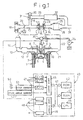
- Fig. 1 is an overall view of a compression ignition type internal combustion engine
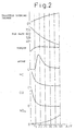
- Fig. 2 is a view of the amount of generation of smoke and NO x
- Figs. 3A and 3B are views of the combustion pressure
- Fig. 4 is a view of a fuel molecule
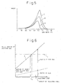
- Fig. 5 is a view of the relationship between the amount of generation of smoke and the EGR rate
- Fig. 6 is a view of the relationship between the amount of injected fuel and the amount of mixed gas
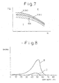
- Fig. 7 is a view of a first operating region I and a second operating region II
- Fig. 8 is a view of the relationship between the amount of production of smoke and the EGR rate
- Fig. 9 is a view of the opening degree of a throttle valve etc.
- Figs. 1 is an overall view of a compression ignition type internal combustion engine
- Fig. 2 is a view of the amount of generation of smoke and NO x
- Figs. 3A and 3B are views of the combustion pressure
- FIG. 10A and 10B are views of the required load
- Fig. 11 is a view of the air-fuel ratio in the first operating region I
- Figs. 12A and 12B are views of maps of the amount of injection etc.
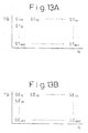
- Figs. 13A and 13B are views of maps of the target opening degree of the throttle valve etc.
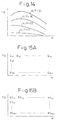
- Fig. 14 is a view of the air-fuel ratio in second combustion
- Figs. 15A and 15B are views of maps of the amount of injection etc.
- Figs. 16A and 16B are views of maps of the target opening degree of the throttle valve etc.
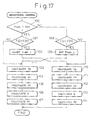
- Fig. 17 is a flow chart of the control of the operation of the engine
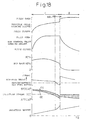
- Fig. 18 is a view of the opening degree of the throttle valve etc.
- Fig. 11 is a view of the air-fuel ratio in the first operating region I
- Figs. 12A and 12B are views of maps of the amount of injection etc.
- Figs. 13A and 13B are views of maps of the target opening degree
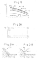
- FIG. 19 is a view of the air-fuel ratio in the first operating region I;
- Fig. 20 is a view of a map of the amount of injection;
- Figs. 21A and 21B are views for explaining the action of absorption and release of NO x ;
- Figs. 22A and 22B are views of maps of the amount of NO x absorption per unit time;
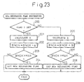
- Fig. 23 is a flow chart-of the processing of the NO x release flag;
- Fig. 24 is a flow chart of the control of the operation of the engine.
- Figure 1 is a view of the case of application of the present invention to a four-stroke compression ignition type internal combustion engine.
- FIG. 1 shows an engine body, 2 a cylinder block, 3 a cylinder head, 4 a piston, 5 a combustion chamber, 6 an electrically controlled fuel injector, 7 an intake valve, 8 an intake port, 9 an exhaust valve, and 10 an exhaust port.
- the intake port 8 is connected through a corresponding intake tube 11 to the surge tank 12.
- the surge tank 12 is connected through an intake duct 13 and intercooler 14 to a supercharger, for example, the exit part of a compressor 16 of an exhaust turbocharger 15.
- the entrance part of the compressor 16 is connected through an air intake pipe 17 to an air cleaner 18.
- a throttle valve 20 driven by a step motor 19 is arranged in the air intake pipe 17.
- the exhaust port 10 is connected through an exhaust manifold 21 and exhaust tube 22 to the entrance part of an exhaust turbine 23 of the exhaust turbocharger 15.
- the exit part of the exhaust turbine 23 is connected through an exhaust pipe 24 to a catalytic converter 26 housing an NO x absorbent 25.
- the exhaust pipe 28 connected to the exit part of the catalytic converter 26 and the air intake pipe 17 downstream of the throttle valve 20 are connected to each other through an EGR passage 29.
- an EGR control valve 31 driven by a step motor 30 is arranged in the EGR passage 29.
- an intercooler 32 for cooling the EGR gas flowing through the EGR passage 29.
- the engine cooling water is led into the intercooler 32 and that engine cooling water used to cool the EGR gas.
- each fuel injector 6 is connected through a fuel supply line 33 to a fuel reservoir, that is, a common rail 34.
- Fuel is supplied to the common rail 34 from an electrically controlled variable discharge fuel pump 35.
- Fuel supplied in the common rail 35 is supplied through the fuel supply lines 33 to the fuel injectors 6.
- a fuel pressure sensor 36 for detecting the fuel pressure in the common rail 34 is attached to the common rail 34. The amount of discharge of the fuel pump 35 is controlled based on the output signal of the fuel pressure sensor 36 so that the fuel pressure in the common rail 34 becomes the target fuel pressure.
- the electronic control unit 40 is comprised of a digital computer and is provided with a ROM (read only memory) 42, a RAM (random access memory) 43, a CPU (microprocessor) 44, an input port 45, and an output port 46 connected with each other by a bidirectional bus 41.
- the output signal of the fuel pressure sensor 36 is input through a corresponding AD converter 47 to the input port 45.
- the accelerator pedal 50 has connected to it a load sensor 51 for generating an output voltage proportional to the amount of depression L of the accelerator pedal 50.
- the output voltage of the load sensor 51 is input through a corresponding AD converter 47 to the input port 45.
- the input port 45 has connected to it a crank angle sensor 52 for generating an output pulse each time the crankshaft rotates by for example 30°.
- the output port 46 has connected to it through a corresponding drive circuit 48 the fuel injectors 6, throttle valve control step motor 19, EGR control valve control step motor 30, and fuel pump 35.
- FIG. 2 shows an example of an experiment showing the changes in the output torque when changing the air fuel ratio A/F (abscissa in Fig. 2 ) by changing the opening degree of the throttle valve 20 and the EGR rate at the time of engine low load operation and the changes in the amount of emission of smoke, HC, CO, and NO x .
- the EGR rate becomes larger the smaller the air fuel ratio A/F.
- the EGR rate becomes over 65 percent.
- Figure 3A shows the changes in compression pressure in the combustion chamber 5 near an air fuel ratio A/F of 21 when the amount of smoke produced is the greatest.
- Figure 3B shows the changes in compression pressure in the combustion chamber 5 near an air fuel ratio A/F of 18 when the amount of smoke produced is substantially zero.
- the combustion pressure is lower in the case shown in Fig. 3B where the amount of smoke produced is substantially zero than the case shown in Fig. 3A where the amount of smoke produced is large.
- the temperature of the fuel and its surroundings when the process of production of hydrocarbons stops in the state of the soot precursor that is, the above certain temperature
- soot precursor or a state of hydrocarbons before this can be easily removed by after-treatment using a catalyst having an oxidation function.
- a catalyst having an oxidation function there is an extremely great difference between whether the hydrocarbons are exhausted from the combustion chamber 5 in the form of a soot precursor or a state before that or exhausted from the combustion chamber 5 in the form of soot.
- the new combustion system used in the present invention is based on the idea of exhausting the hydrocarbons from the combustion chamber 5 in the form of a soot precursor or a state before that without allowing the production of soot in the combustion chamber 5 and causing the hydrocarbons to oxidize by a catalyst having an oxidation function.
- the vaporized fuel will immediately react with the oxygen in the air and burn.
- the temperature of the air away from the fuel does not rise that much. Only the temperature around the fuel becomes locally extremely high. That is, at this time, the air away from the fuel does not absorb the heat of combustion of the fuel much at all. In this case, since the combustion temperature becomes extremely high locally, the unburned hydrocarbons receiving the heat of combustion produce soot.
- the inert gas is preferably a gas with a large specific heat.
- CO 2 and EGR gas have relatively large specific heats, it may be said to be preferable to use EGR gas as the inert gas.
- Figure 5 shows the relationship between the EGR rate and smoke when using EGR gas as the inert gas, making the injection timing before top dead center of the compression stroke, and changing the degree of cooling of the EGR gas. That is, the curve A in Fig. 5 shows the case of force cooling the EGR gas and maintaining the temperature of the EGR gas at about 90°C, curve B shows the case of cooling the EGR gas by a compact cooling apparatus, and curve C shows the case of not force cooling the EGR gas.
- Fig. 5 shows the amount of smoke produced when the engine load is relatively high.
- the EGR rate at which the amount of soot produced peaks falls somewhat and the lower limit of the EGR rate at which almost no soot is produced any longer falls somewhat.
- the lower limit of the EGR rate at which almost no soot is produced any longer changes in accordance with the degree of cooling of the EGR gas or the engine load.
- Figure 6 shows the amount of mixed gas of EGR gas and air, the ratio of air in the mixed gas, and the ratio of EGR gas in the mixed gas required for making the temperature of the fuel and the gas around it at the time of combustion a temperature lower than the temperature at which soot is produced in the case of use of EGR gas as an inert gas.
- the ordinate shows the total amount of suction gas taken into the combustion chamber 5.
- the broken line Y shows the total amount of suction gas able to be taken into the combustion chamber 5 when supercharging is not being performed. Further, the abscissa shows the required load.
- the ratio of air that is, the amount of air in the mixed gas
- the ratio of air and the amount of injected fuel becomes the stoichiometric air fuel ratio.
- the ratio of EGR gas that is, the amount of EGR gas in the mixed gas
- the temperature of the fuel and the gas around it becomes a temperature lower than the temperature at which soot is produced and therefore no soot at all is produced any longer. Further, the amount of NO x produced at this time is around 10 ppm or less and therefore the amount of NO x produced becomes extremely small.
- the amount of fuel injected increases, the amount of heat generated at the time of combustion increases, so to maintain the temperature of the fuel and the gas around it at a temperature lower than the temperature at which soot is produced, the amount of heat absorbed by the EGR gas must be increased. Therefore, as shown in Fig. 6 , the amount of EGR gas has to be increased the greater the amount of injected fuel. That is, the amount of EGR gas has to be increased as the required load becomes higher.
- the EGR rate of the suction gas raised in pressure by the compressor 16 of the exhaust turbocharger 15 also becomes 70 percent and therefore it is possible to maintain the temperature of the fuel and its surrounding gas at a temperature lower than the temperature where soot is produced up to the limit to which the pressure can be raised by the compressor 16. Therefore, it becomes possible to enlarge the operating region of the engine where low temperature combustion can be performed.
- Fig. 6 shows the case of combustion of fuel at the stoichiometric air fuel ratio. Even if the amount of air is made smaller than the amount of air shown in Fig. 6 , however, that is, even if the air fuel ratio is made rich, it is possible to obstruct the production of soot and make the amount of NO x produced around 10 ppm or less. Further, even if the amount of air is made greater than the amount of air shown in Fig. 6 , that is, the mean value of the air fuel ratio is made a lean 17 to 18, it is possible to obstruct the production of soot and make the amount of NO x produced around 10 ppm or less.
- the temperature of the fuel and its surrounding gas at the time of combustion in the combustion chamber can only be suppressed to not more than a temperature where the growth of hydrocarbons stops midway during engine medium or low load operation where the amount of heat generated by the combustion is relatively small. Therefore, in this embodiment of the present invention, at the time of medium or low load operation of the engine, the temperature of the fuel and its surrounding gas at the time of combustion is suppressed to not more than a temperature at which the growth of the hydrocarbons stops midway and first combustion, that is, low temperature combustion, is performed, while at the time of high load operation of the engine, second combustion, that is, the conventionally performed combustion, is performed.
- the first combustion that is, the low temperature combustion
- the second combustion that is, the conventionally normally performed combustion
- the second combustion means combustion where the amount of inert gas in the combustion chamber is smaller than the amount of inert gas where the amount of production of soot peaks.
- Figure 7 shows a first operating region I where the first combustion, that is, the low temperature combustion, is performed and a second operating region II where the second combustion, that is, the combustion by the conventional combustion method, is performed.
- the ordinate TQ shows the required torque
- the abscissa N shows the engine rotational speed N.
- X(N) shows a first boundary between the first operating region I and the second operating region II
- Y(N) shows a second boundary between the first operating region I and the second operating region II
- the first reason is that at the high torque side of the second operating region II, the combustion temperature is relatively high and at this time, even if the required torque TQ becomes lower than the first boundary X(N), low temperature combustion cannot be performed immediately. That is, low temperature combustion cannot be started immediately unless the required torque TQ is considerably low, that is, lower than the second boundary Y(N).
- the second reason is to provide hysteresis with respect to the change in operating regions between the first operating region I and the second operating region II.
- the air-fuel ratio is made lean or the stoichiometric air-fuel ratio and the injection timing is delayed until after top dead center of the compression stroke.
- the region RR is always passed through. This region RR is also always passed through when the engine operating state shifts from the second operating state II to the first operating state I.
- the unburned hydrocarbons are exhausted from the combustion chamber 5 in the form of soot precursors or a state before that. At this time, the unburned hydrocarbons exhausted from the combustion chamber 5 can be oxidized well by a catalyst 25 having an oxidation function.
- an oxidation catalyst, three-way catalyst, or NO x absorbent may be used as the catalyst 25 as the catalyst 25, an oxidation catalyst, three-way catalyst, or NO x absorbent may be used.
- An NO x absorbent has the function of absorbing NO x when the mean air-fuel ratio in the combustion chamber 5 is lean, while releasing NO x when the mean air-fuel ratio in the combustion chamber 5 becomes rich.
- the NO x absorbent is for example comprised of alumina as a carrier and, on the carrier, for example, at least one of potassium K, sodium Na, lithium Li, cesium Cs, and other alkali metals, barium Ba, calcium Ca, and other alkali earths, lanthanum La, yttrium Y, and other rare earths plus platinum Pt or another precious metal.
- An oxidation catalyst of course, and also a three-way catalyst and an NO x absorbent have an oxidation function. Therefore, as explained above, it is possible to use a three-way catalyst and NO x absorbent as the catalyst 25.
- Figure 9 shows the opening degree of the throttle valve 20, the opening degree of the EGR control valve 31, the EGR rate, the air-fuel ratio, the injection timing, and the amount of injection with respect to the required torque TQ.
- the opening degree of the throttle valve 20 is gradually increased from the fully closed state to the 2/3 opened state as the required torque TQ becomes higher, while the opening degree of the EGR control valve 31 is gradually increased from close to the fully closed state to the fully opened state as the required torque TQ becomes higher.
- the EGR rate is made at least about 55 percent and the air-fuel ratio is made a slightly lean lean air-fuel ratio.
- the opening degree of the throttle valve 20 and the opening degree of the EGR control valve 31 are controlled so that the EGR rate becomes at least about 55 percent and the air-fuel ratio becomes a slightly lean lean air-fuel ratio.
- the fuel is injected before top dead center TDC of the compression stroke.
- the injection start timing ⁇ S becomes later the higher the required torque TQ.
- the injection end timing ⁇ E also becomes later the later the injection start timing ⁇ S.
- the throttle valve 20 is made to close to close to the fully closed state.
- the EGR control valve 31 is also made to close to close to the fully closed state. If the throttle valve 20 is closed to close to the fully closed state, the pressure in the combustion chamber 5 at the start of compression will become low, so the compression pressure will become small. If the compression pressure becomes small, the amount of compression work by the pistons 4 becomes small, so the vibration of the engine body 1 becomes smaller. That is, during idling operation, the throttle valve 20 can be closed to close to the fully closed state to suppress vibration in the engine body 1.
- the injection start timing ⁇ S is delayed more the larger the required torque TQ.
- the injection start timing ⁇ S becomes after top dead center.
- the air-fuel ratio is gradually made smaller from the lean air-fuel ratio to the stoichiometric air-fuel ratio as the required torque TQ becomes larger, while the EGR rate is made lower as the required torque TQ becomes larger.
- the amount of injection can be increased.
- the opening degree of the throttle valve 20 is increased in a step-like manner from the 2/3 opened state to the fully opened state.
- the EGR rate is reduced in a step-like manner from about 40 percent to less than 20 percent and the air-fuel ratio is increased in a step-like manner.
- the second combustion that is, the conventionally performed combustion
- the throttle valve 20 is held in the fully opened state except for a certain part and the opening degree of the EGR control valve 31 is gradually made smaller then higher the required torque TQ. Therefore, in the operating region II, the EGR rate becomes lower the higher the required torque TQ and the air-fuel ratio becomes smaller then higher the required torque. Even if the required torque TQ becomes high, however, the air-fuel ratio is made a lean air-fuel ratio. Further, in the second operating region II, the injection start timing ⁇ S is made before top dead center TDC of the compression stroke.
- the required torques TQ shown in Fig. 10A are stored in the ROM 42 in advance in the form of a map as a function of the amount of depression L of the accelerator pedal 50 and the engine rotational speed N as shown in Fig. 10B .
- the required torque TQ is first calculated in accordance with the amount of depression L of the accelerator pedal 50 and the engine rotational speed N from the map shown in Fig. 10B and then the amount of fuel injection etc. are calculated based on the required torque TQ.
- Figure 11 shows the air-fuel ratio A/F in the first operating region I.
- the air-fuel ratios between the curves are determined by proportional distribution.
- the air-fuel ratio becomes lean.
- the air-fuel ratio A/F is made lean the lower the required torque TQ becomes.
- the air-fuel ratio A/F is made larger the lower the required torque TQ.
- the air-fuel ratio A/F is made larger the lower the required torque TQ.
- Figure 12A shows the amount of injection Q in the first operating region
- Fig. 12B shows the injection start timing ⁇ S in the first operating region I.
- the amount of injection Q in the first operating region I is stored in advance in the ROM 42 in the form of a map as a function of the required torque TQ and the engine rotational speed N as shown in Fig. 12A .
- the injection start timing ⁇ S in the first operating region I is stored in advance in the ROM 42 as a function of the required torque TQ and the engine rotational speed N as shown in Fig. 12B .
- the target opening degree ST of the throttle valve 20 required for making the air-fuel ratio the target air-fuel ratio shown in Fig. 11 is stored in advance in the ROM 42 in the form of a map as a function of the required torque TQ and the engine rotational speed N as shown in Fig. 13A
- the target opening degree SE of the EGR control valve 31 required for making the air-fuel ratio the target air-fuel ratio shown in Fig. 11 is stored in advance in the ROM 42 in the form of a map as a function of the required torque TQ and the engine rotational speed N as shown in Fig. 13B .
- Figure 15A shows the amount of injection Q in the second operating region II
- Fig. 15B shows the injection start timing ⁇ S in the second operating region II
- the amount of injection Q in the second operating region II is stored in advance in the ROM 42 in the form of a map as a function of the required torque TQ and the engine rotational speed N as shown in Fig. 15A
- the injection start timing ⁇ S in the second operating region II is stored in advance in the ROM 42 in the form of a map as a function of the required torque TQ and the engine rotational speed N as shown in Fig. 15B .
- the target opening degree ST of the throttle valve 20 required for making the air-fuel ratio the target air-fuel ratio shown in Fig. 14 is stored in advance in the ROM 42 in the form of a map as a function of the required torque TQ and the engine rotational speed N as shown in Fig. 16A
- the target opening degree SE of the EGR control valve 31 required for making the air-fuel ratio the target air-fuel ratio shown in Fig. 14 is stored in advance in the ROM 42 in the form of a map as a function of the required torque TQ and the engine rotational speed N as shown in Fig. 16B .
- step 100 it is judged if a flag I showing that the engine operating region is the first operating region I is set or not.
- the flag I is set, that is, when the engine operating region is the first operating region I
- the routine proceeds to step 101, where it is determined if the required torque TQ has become larger than the first boundary X1(N).
- TQ ⁇ X1(N) the routine proceeds to step 103, where low temperature combustion is performed.
- the required torque TQ is calculated from the map shown in Fig. 10A .
- the target opening degree ST of the throttle valve 20 is calculated from the map shown in Fig. 13A and the opening degree of the throttle valve 20 is made this target opening degree ST.
- the target opening degree SE of the EGR control valve 31 is calculated from the map shown in Fig. 13B and the opening degree of the EGR control valve 31 is made this target opening degree SE.
- the amount of injection Q is calculated from the map shown in Fig. 12A .
- the injection start timing ⁇ S is calculated from the map shown in Fig. 12B .
- step 101 when it is determined at step 101 that TQ>X1(N), the routine proceeds to step 102, where the flag I is reset, then the routine proceeds to step 110, where the second combustion is performed.
- the required torque TQ is calculated from the map shown in Fig. 10B .
- the target opening degree ST of the throttle valve 20 is calculated from the map shown in Fig. 16A and the opening degree of the throttle valve 20 is made this target opening degree ST.
- the target opening degree SE of the EGR control valve 31 is calculated from the map shown in Fig. 16B and the opening degree of the EGR control valve 31 is made this target opening degree SE.
- the amount of injection Q is calculated from the map shown in Fig. 15A .
- the injection start timing ⁇ S is calculated from the map shown in Fig. 15B .
- step 100 the routine proceeds from step 100 to step 108, where it is determined if the required torque TQ has become lower than the second boundary Y(N).
- TQ ⁇ Y(N) the routine proceeds to step 110, where the second combustion is performed.
- step 109 the flag I is set, then the routine proceeds to step 103, where low temperature combustion is performed.
- the EGR rate is made lower the larger the required torque TQ by increasing the amount of injection.
- the air-fuel ratio is made gradually smaller from the lean air-fuel ratio to the rich air-fuel ratio as the required torque TQ becomes larger. Therefore, the rate of increase of the amount of injection in the region RR is made larger in the case of the second embodiment shown in Fig. 18 compared with the embodiment shown in Fig. 9 .
- Figure 19 shows the air-fuel ratio A/F in the first operating region I in the second embodiment.
- the air-fuel ratios between the curves are determined by proportional distribution.
- the air-fuel ratio in the first operating region I other than the region RR, the air-fuel ratio becomes lean. Further, in the first operating region I, the air-fuel ratio A/F is made lean the lower the required torque TQ becomes.
- Figure 20 shows the amount of injection Q in the first operating region.
- the amount of injection Q in the first operating region I is stored in advance in the ROM 42 in the form of a map as a function of the required torque TQ and the engine rotational speed N as shown in Fig. 20 .
- the injection start timing ⁇ S, the target opening degree ST of the throttle valve 20, and the target opening degree SE of the EGR control valve 31 are calculated from the maps shown in Fig. 12B , Fig. 13A, and Fig. 13B .
- the air-fuel ratio when switching from the first combustion to the second combustion or from the second combustion to the first combustion, the air-fuel ratio is made rich and the injection start timing ⁇ S is delayed to after top dead center. In this way, there is the advantage that when the air-fuel ratio is made rich, while the amount of fuel consumption increases somewhat, no smoke is produced at all.
- the NO x absorbent 25 has the function of absorbing NO x when the mean air-fuel ratio in the combustion chamber 5 is lean, while releasing NO x when the mean air-fuel ratio in the combustion chamber 5 becomes rich.
- the ratio of the air and fuel (hydrocarbons) supplied into the engine intake passage, combustion chamber 5, and exhaust passage upstream of the NO x absorbent 25 is referred to as the air-fuel ratio of the exhaust gas flowing into the NO x absorbent 25, then the NO x absorbent 25 performs an NO x absorption and release action in which it absorbs NO x when the air-fuel ratio of the inflowing exhaust gas is lean while releases the absorbed NO x when the air-fuel ratio of the inflowing exhaust gas becomes the stoichiometric air-fuel ratio or rich.
- this NO x absorbent 25 will in actuality perform an NO x absorption and release action, but there are portions of the detailed mechanism of this absorption and release action which are still not clear.
- This absorption and release action is considered to be performed by the mechanism shown in Figs. 21A and 21B .
- this mechanism will be explained taking as an example the case of carrying platinum Pt and barium Ba on the carrier, but the same mechanism applies even if using another precious metal and alkali metal, alkali earth, or rare earth.
- combustion is usually performed when the air-fuel ratio in the combustion chamber 5 is in a lean state.
- the concentration of oxygen in the exhaust gas is high.
- the oxygen O 2 deposits on the surface of the platinum Pt in the form of O 2 - or O 2- .
- the NO in the inflowing exhaust gas reacts with the O 2 - or O 2- on the surface of the platinum Pt to become NO 2 (2NO+O 2 ⁇ 2NO 2 ).
- part of the produced NO 2 is oxidized on the platinum Pt and absorbed in the absorbent and diffuses inside the absorbent in the form of nitrate ions NO 3 - as shown in Fig. 21A while bonding with the barium oxide BaO.
- the NO x is absorbed in the NO x absorbent 25 in this way. So long as the concentration of oxygen in the inflowing exhaust gas is high, NO 2 is produced on the surface of the platinum Pt. So long as the NO x absorption capability of the absorbent does not become saturated, the NO 2 is absorbed in the absorbent and nitrate ions NO 3 - are produced.
- the concentration of oxygen in the inflowing exhaust gas falls and as a result the amount of production of NO 2 on the surface of the platinum Pt falls. If the amount of production of NO 2 falls, the reaction proceeds in the reverse direction (NO 3 - -NO 2 ) and therefore the nitrate ions NO 3 - in the absorbent are released from the absorbent in the form of NO 2 . At this time, the NO x released from the NO x absorbent 25 reacts with the large amount of unburnt hydrocarbons and carbon monoxide contained in the inflowing exhaust gas to be reduced as shown in Fig. 21B .
- the amount of NO x absorption A per unit time when the first combustion is being performed is found in advance in the form of the map shown in Fig. 22A as a function of the required load L and the engine rotational speed N, while the amount of NO x absorption B per unit time when the second combustion is being performed is found in advance in the form of the map shown in Fig. 22B as a function of the required load L and the engine rotational speed N.
- the amount ⁇ NOX of NO x absorbed in the NO x absorbent 25 is estimated by cumulative addition of these amounts of NO x absorption A and B per unit time.
- the NO x when the amount ⁇ NOX of NO x absorption exceeds a predetermined maximum allowable value, the NO x is made to be released from the NO x absorbent 25. That is, specifically speaking, when ⁇ NOX ⁇ MAX, the air-fuel ratio and the injection start timing ⁇ S etc. are controlled as shown in Fig. 9 . As opposed to this, when ⁇ NOX>MAX, the air-fuel ratio and the injection start timing ⁇ S etc. are controlled as shown in Fig. 18 . Therefore, at this time, NO x is released from the NO x absorbent when the air-fuel ratio is made rich at the time of switching between the first combustion and the second combustion.
- step 200 it is judged if a flag I showing that the engine operating region is the first operating region I is set or not.
- the routine proceeds to step 201, where the amount of absorption of NO x per unit time is calculated from the map shown in Fig. 22A .
- step 202 A is added to the amount ⁇ NOX of absorption of NO x .
- step 203 it is determined if the amount ⁇ NOX of absorption of NO x has exceeded a maximum allowable value MAX. If ⁇ NOX>MAX, the routine proceeds to step 204, where the NO x releasing flag showing that NO x should be released is set.
- step 200 when it is determined at step 200 that the flag I has been reset, that is, when the operating state of the engine is the second operating region II, the routine proceeds to step 205, where the amount B of absorption of NO x per unit time is calculated from the map shown in Fig. 22B .
- step 206 B is added to the amount ⁇ NOX of the absorption of NO x .
- step 207 it is determined if the amount ⁇ NOX of the absorption of NO x has exceeded the maximum allowable value MAX. When ⁇ NOX>MAX1, the routine proceeds to step 208, where the NO x releasing flag showing that NO x should be released is set.
- step 300 it is determined if a flag I indicating the operating state of the engine is the first operating region I has been set or not.
- the routine proceeds to step 301, where it is determined if the required torque TQ has become larger than the first boundary X1(N).
- TQ ⁇ X1(N) the routine proceeds to step 303, where low temperature combustion is performed.
- the required torque TQ is calculated from the map shown in Fig. 10B .
- the target degree of opening ST of the throttle valve 20 is calculated from the map shown in Fig. 13A and the degree of opening of the throttle valve 20 is made this target degree of opening ST.
- the target degree of opening SE of the EGR control valve 31 is calculated from the map shown in Fig. 13B and the degree of opening of the EGR control valve 31 is made this target degree of opening SE.
- the injection start timing ⁇ S is calculated from the map shown in Fig. 12B .
- step 307 it is determined if the NO x releasing flag has been set.
- the routine proceeds to step 308, where the amount of injection Q is calculated from the map shown in Fig. 12A .
- the routine proceeds to step 309, where processing is performed to release NO x from the NO x absorbent 25.
- step 309 first, the amount of injection Q is calculated from the map shown in Fig. 20 . Next, it is determined if the air-fuel ratio has been made rich for more than a predetermined period. When the air-fuel ratio has been made rich for more than a predetermined period, the NO x releasing flag 1 is reset.
- step 301 when it is determined at step 301 that TQ>X(N), the routine proceeds to step 302, where the flag I is reset, then the routine proceeds to step 312, where the second combustion is performed.
- the required torque TQ is calculated from the map shown in Fig. 10B .
- the target opening degree ST of the throttle valve 20 is calculated from the map shown in Fig. 16A and the opening degree of the throttle valve 20 is made this target opening degree ST.
- the target opening degree SE of the EGR control valve 31 is calculated from the map shown in Fig. 16B and the opening degree of the EGR control valve 31 is made this target opening degree SE.
- the amount of injection Q is calculated from the map shown in Fig. 15A .
- the injection start timing ⁇ S is calculated from the map shown in Fig. 15B .
- step 300 the routine proceeds from step 300 to step 310, where it is determined if the required torque TQ has become lower than the second boundary Y(N).
- TQ ⁇ Y(N) the routine proceeds to step 312, where the second combustion is performed.
- step 311 where the flag I is set, then the routine proceeds to step 303, where low temperature combustion is performed.
Landscapes
- Engineering & Computer Science (AREA)
- Chemical & Material Sciences (AREA)
- Combustion & Propulsion (AREA)
- Mechanical Engineering (AREA)
- General Engineering & Computer Science (AREA)
- Exhaust-Gas Circulating Devices (AREA)
- Electrical Control Of Air Or Fuel Supplied To Internal-Combustion Engine (AREA)
- Exhaust Gas After Treatment (AREA)
- Output Control And Ontrol Of Special Type Engine (AREA)
Claims (13)
- Brennkraftmaschine, in der eine Erzeugungsmenge an Ruß fortschreitend steigt und dann eine Spitze erreicht, wenn eine Menge an Inertgas in einer Brennkammer steigt, und in der eine weitere Erhöhung der Menge an Intertgas in der Brennkammer darin resultiert, dass eine Temperatur von Kraftstoff und umgebendem Gas in der Brennkammer niedriger als eine Erzeugungstemperatur von Ruß wird, und daher in fast keiner Erzeugung von Ruß resultiert, wobei die Maschine eine Umschalteinrichtung zum wahlweisen Umschalten zwischen einer ersten Verbrennung, in der die Menge des Inertgases in der Brennkammer größer als die Menge an Inertgas ist, bei der die Erzeugungsmenge an Ruß eine Spitze erreicht und fast kein Ruß erzeugt wird, und einer zweiten Verbrennung, in der die Menge an Inertgas in der Brennkammer kleiner als die Menge an Inertgas ist, bei der die Erzeugungsmenge an Ruß eine Spitze erreicht, und wobei eine Einspritzsteuerzeit bis nach einem oberen Totpunkt eines Kompressionshubs verzögert wird, wenn zwischen der ersten Verbrennung und der zweiten Verbrennung umgeschaltet wird.
- Brennkraftmaschine nach Anspruch 1, wobei, wenn zwischen der ersten Verbrennung und der zweiten Verbrennung umgeschaltet wird, bei der ersten Verbrennung das Luftkraftstoffverhältnis mager oder als stöchiometrisches Luftkraftstoffverhältnis ausgeführt wird und die Einspritzsteuerzeit bis nach dem oberen Totpunkt des Kompressionshubs verzögert wird.
- Brennkraftmaschine nach Anspruch 1, wobei der Betriebsbereich der Maschine in einen niedriglastseitigen ersten Betriebsbereich und einen hochlastseitigen zweiten Betriebsbereich geteilt ist, die erste Verbrennung in dem ersten Betriebsbereich ausgeführt wird und die zweite Verbrennung in dem zweiten Betriebsbereich ausgeführt wird.
- Brennkraftmaschine nach Anspruch 3, wobei in einem Bereich in dem ersten Betriebsbereich, in dem die Last am höchsten ist, das Luftkraftstoffverhältnis mager oder als stöchiometrisches Luftkraftstoffverhältnis ausgeführt wird und die Einspritzsteuerzeit bis nach einem oberen Totpunkt des Kompressionshubs verzögert wird.
- Brennkraftmaschine nach Anspruch 4, wobei eine Abgasrezirkulierungsvorrichtung zum Rezirkulieren von Abgas vorgesehen ist, das von der Brennkammer in einen Eingangsdurchgang der Maschine abgegeben wird, wobei das Inertgas aus dem rezikulierten Abgas besteht, die Abgasrezirkulierungsrate größer als ungefähr 55 Prozent in dem ersten Betriebsbereich I anders als in dem Bereich, in dem die Last am höchsten ist, ausgeführt ist, und die Abgasrezirkulationsrate geringer als 55 Prozent in dem Bereich ausgeführt ist, in dem die Last am höchsten ist.
- Brennkraftmaschine nach Anspruch 1, wobei ein Katalysator, der eine Oxidationsfunktion hat, in dem Maschinenabgasdurchgang angeordnet ist.
- Brennkraftmaschine nach Anspruch 6, wobei der Katalysator aus zumindest einem von einem Oxidationskatalysator, Dreiwegekatalysator und einem NOx Absorptionsmittel besteht.
- Brennkraftmaschine nach Anspruch 1, wobei, wenn zwischen der ersten Verbrennung und der zweiten Verbrennung umgeschaltet wird, bei der ersten Verbrennung das Luftkraftstoffverhältnis fett ausgeführt wird und die Einspritzsteuerzeit bis nach einem oberen Totpunkt des Kompressionshubs verzögert wird.
- Brennkraftmaschine nach Anspruch 8, wobei der Betriebsbereich der Maschine in einen niedriglastseitigen ersten Betriebsbereich und einen hochlastseitigen zweiten Betriebsbereich geteilt ist, die erste Verbrennung in dem ersten Betriebsbereich ausgeführt wird und die zweite Verbrennung in dem zweiten Betriebsbereich ausgeführt wird.
- Brennkraftmaschine nach Anspruch 1, wobei in einem Bereich in dem ersten Betriebsbereich, in dem die Last am höchsten ist, das Luftkraftstoffverhältnis fett ausgeführt wird und die Einspritzsteuerzeit bis nach einem oberen Totpunkt des Kompressionshubs verzögert wird.
- Brennkraftmaschine nach Anspruch 10, wobei eine Abgasrezirkulierungsvorrichtung zum Rezirkulieren von Abgas vorgesehen ist, das von der Brennkammer in einen Eingangsdurchgang der Maschine abgegeben wird, wobei das Inertgas aus rezirkuliertem Abgas besteht, die Abgasrezirkulierungsrate größer als ungefähr 55 Prozent in dem ersten Betriebsbereich I anders als in dem Bereich ausgeführt wird, in dem die Last am höchsten ist, und die Abgasrezirkulierungsrate auf weniger als 55 Prozent in dem Bereich ausgeführt wird, in dem die Last am höchsten ist.
- Brennkraftmaschine nach Anspruch 8, wobei ein Katalysator, der eine Oxidationsfunktion hat, in dem Maschinenabgasdurchgang angeordnet ist.
- Brennkraftmaschine nach Anspruch 1, wobei ein NOx Absorptionsmittel in dem Maschinenabgasdurchgang angeordnet ist, unter einer ersten Verbrennung das Luftkraftstoffverhältnis mager oder als stöchiometrisches Luftkraftstoffverhältnis ausgeführt wird und die Einspritzsteuerzeit bis nach einem oberen Totpunkt des Kompressionshubs verzögert ist, wenn zwischen der ersten Verbrennung und der zweiten Verbrennung zu normalen Zeiten umgeschaltet wird, und das Luftkraftstoffverhältnis fett ausgeführt wird und die Einspritzsteuerzeit bis nach dem oberen Totpunkt des Kompressionshubs unter der ersten Verbrennung verzögert wird, wenn zwischen der ersten Verbrennung und der zweiten Verbrennung umgeschaltet wird, wenn NOx von dem NOx Absorptionsmittel abzugeben ist.
Applications Claiming Priority (3)
| Application Number | Priority Date | Filing Date | Title |
|---|---|---|---|
| JP10322522A JP3092604B2 (ja) | 1998-11-12 | 1998-11-12 | 内燃機関 |
| JP32252298 | 1998-11-12 | ||
| PCT/JP1999/005948 WO2000029735A1 (en) | 1998-11-12 | 1999-10-27 | Internal combustion engine |
Publications (3)
| Publication Number | Publication Date |
|---|---|
| EP1132597A1 EP1132597A1 (de) | 2001-09-12 |
| EP1132597A4 EP1132597A4 (de) | 2008-05-07 |
| EP1132597B1 true EP1132597B1 (de) | 2010-05-19 |
Family
ID=18144611
Family Applications (1)
| Application Number | Title | Priority Date | Filing Date |
|---|---|---|---|
| EP99951100A Expired - Lifetime EP1132597B1 (de) | 1998-11-12 | 1999-10-27 | Brennkraftmaschine |
Country Status (9)
| Country | Link |
|---|---|
| US (1) | US6715474B1 (de) |
| EP (1) | EP1132597B1 (de) |
| JP (1) | JP3092604B2 (de) |
| KR (1) | KR100404354B1 (de) |
| CN (1) | CN1107162C (de) |
| CA (1) | CA2350737C (de) |
| DE (1) | DE69942395D1 (de) |
| ES (1) | ES2346728T3 (de) |
| WO (1) | WO2000029735A1 (de) |
Cited By (1)
| Publication number | Priority date | Publication date | Assignee | Title |
|---|---|---|---|---|
| DE10048238B4 (de) * | 2000-09-29 | 2014-09-18 | Daimler Ag | Verfahren zum Betrieb einer Dieselbrennkraftmaschine |
Families Citing this family (12)
| Publication number | Priority date | Publication date | Assignee | Title |
|---|---|---|---|---|
| JP2002206448A (ja) * | 2000-11-08 | 2002-07-26 | Denso Corp | 内燃機関の排気浄化装置 |
| JP4691822B2 (ja) * | 2001-04-27 | 2011-06-01 | トヨタ自動車株式会社 | 内燃機関の制御装置 |
| JP2003138952A (ja) | 2001-11-05 | 2003-05-14 | Mitsubishi Motors Corp | ディーゼル機関 |
| AT7207U1 (de) * | 2002-10-22 | 2004-11-25 | Avl List Gmbh | Verfahren zum betreiben einer direkteinspritzenden diesel-brennkraftmaschine |
| US6968830B2 (en) | 2003-12-30 | 2005-11-29 | General Electric Company | Apparatus and method for suppressing internal combustion ignition engine emissions |
| JP2005344677A (ja) * | 2004-06-07 | 2005-12-15 | Mitsubishi Fuso Truck & Bus Corp | エンジンの制御装置 |
| JP4300364B2 (ja) * | 2004-09-29 | 2009-07-22 | 日産自動車株式会社 | 可変過給システムの過給圧調整装置 |
| EP1701027B1 (de) * | 2005-03-11 | 2016-12-28 | Ford Global Technologies, Inc. | Methode für die Regeneration eines NOx-Speichers in einem Dieselmotors mittels Kompressionszündung einer teilweise homogenen Ladung |
| JP4626774B2 (ja) * | 2007-08-06 | 2011-02-09 | 三菱自動車工業株式会社 | ディーゼル機関 |
| FR2943385B1 (fr) * | 2009-03-19 | 2014-07-18 | Renault Sas | Dispositif et procede de commande de l'injection de carburant dans un moteur en fonction du taux de recirculation partielle des gaz d'echappement |
| JP6136947B2 (ja) * | 2014-01-23 | 2017-05-31 | トヨタ自動車株式会社 | 内燃機関の制御装置 |
| US11598243B2 (en) * | 2020-02-22 | 2023-03-07 | Enginuity Power Systems, Inc. | Four-stroke opposed piston engine architecture and related methods |
Family Cites Families (15)
| Publication number | Priority date | Publication date | Assignee | Title |
|---|---|---|---|---|
| US4805571A (en) | 1985-05-15 | 1989-02-21 | Humphrey Cycle Engine Partners, L.P. | Internal combustion engine |
| JPH01122535A (ja) | 1987-11-05 | 1989-05-15 | Matsushita Electric Ind Co Ltd | 感温スイッチ |
| DE3831490A1 (de) | 1988-09-16 | 1990-03-29 | Stihl Maschf Andreas | Kraftstoffeinspritzvorrichtung |
| US5095873A (en) | 1989-09-13 | 1992-03-17 | Yamaha Hatsudoki Kabushiki Kaisha | Fuel injection system and method for engine |
| JPH08303309A (ja) | 1995-05-10 | 1996-11-19 | Nissan Motor Co Ltd | 過給機付きディーゼル機関のegr装置 |
| DE69727417T2 (de) | 1996-04-23 | 2004-12-16 | Toyota Jidosha K.K., Toyota | Selbstzündende Brennkraftmaschine |
| JP3134766B2 (ja) * | 1996-04-23 | 2001-02-13 | トヨタ自動車株式会社 | 筒内噴射式内燃機関 |
| JP3839521B2 (ja) | 1996-05-21 | 2006-11-01 | 松下冷機株式会社 | 自動販売機 |
| JP3116876B2 (ja) | 1997-05-21 | 2000-12-11 | トヨタ自動車株式会社 | 内燃機関 |
| JP3713908B2 (ja) | 1997-07-07 | 2005-11-09 | トヨタ自動車株式会社 | 圧縮着火式内燃機関 |
| JP3092552B2 (ja) * | 1997-09-16 | 2000-09-25 | トヨタ自動車株式会社 | 圧縮着火式内燃機関 |
| JP3094974B2 (ja) | 1997-09-16 | 2000-10-03 | トヨタ自動車株式会社 | 圧縮着火式内燃機関 |
| JP3622446B2 (ja) * | 1997-09-30 | 2005-02-23 | 日産自動車株式会社 | ディーゼルエンジンの燃焼制御装置 |
| JP3331935B2 (ja) * | 1997-12-04 | 2002-10-07 | トヨタ自動車株式会社 | 圧縮着火式内燃機関 |
| EP0952323B1 (de) * | 1998-04-15 | 2004-03-31 | Toyota Jidosha Kabushiki Kaisha | Brennkraftmaschine |
-
1998
- 1998-11-12 JP JP10322522A patent/JP3092604B2/ja not_active Expired - Fee Related
-
1999
- 1999-10-27 EP EP99951100A patent/EP1132597B1/de not_active Expired - Lifetime
- 1999-10-27 CN CN99813222A patent/CN1107162C/zh not_active Expired - Fee Related
- 1999-10-27 ES ES99951100T patent/ES2346728T3/es not_active Expired - Lifetime
- 1999-10-27 US US09/831,559 patent/US6715474B1/en not_active Expired - Fee Related
- 1999-10-27 CA CA002350737A patent/CA2350737C/en not_active Expired - Fee Related
- 1999-10-27 KR KR10-2001-7005614A patent/KR100404354B1/ko not_active Expired - Fee Related
- 1999-10-27 DE DE69942395T patent/DE69942395D1/de not_active Expired - Lifetime
- 1999-10-27 WO PCT/JP1999/005948 patent/WO2000029735A1/ja not_active Ceased
Cited By (1)
| Publication number | Priority date | Publication date | Assignee | Title |
|---|---|---|---|---|
| DE10048238B4 (de) * | 2000-09-29 | 2014-09-18 | Daimler Ag | Verfahren zum Betrieb einer Dieselbrennkraftmaschine |
Also Published As
| Publication number | Publication date |
|---|---|
| JP3092604B2 (ja) | 2000-09-25 |
| EP1132597A4 (de) | 2008-05-07 |
| KR20010099778A (ko) | 2001-11-09 |
| WO2000029735A1 (en) | 2000-05-25 |
| ES2346728T3 (es) | 2010-10-19 |
| CA2350737C (en) | 2005-05-17 |
| CN1107162C (zh) | 2003-04-30 |
| CN1326532A (zh) | 2001-12-12 |
| EP1132597A1 (de) | 2001-09-12 |
| DE69942395D1 (de) | 2010-07-01 |
| CA2350737A1 (en) | 2000-05-25 |
| US6715474B1 (en) | 2004-04-06 |
| KR100404354B1 (ko) | 2003-11-05 |
| JP2000145509A (ja) | 2000-05-26 |
Similar Documents
| Publication | Publication Date | Title |
|---|---|---|
| EP0896141B1 (de) | Steuerung für Verbrennung und Abgasrückführung in einer Brennkraftmaschine | |
| US6276130B1 (en) | Internal combustion engine | |
| EP0879946B1 (de) | Brennkraftmaschine | |
| EP0943790B1 (de) | Brennkraftmaschine mit Kompressionszündung | |
| US6470850B1 (en) | Internal combustion engine | |
| US6240723B1 (en) | Compression ignition type engine | |
| EP0919708B1 (de) | Brennkraftmaschine mit Kompressionszündung | |
| EP0947685B1 (de) | Selbszündende Brennkraftmaschine | |
| EP1132597B1 (de) | Brennkraftmaschine | |
| EP0964140B1 (de) | Motor mit Verdichtungszündung | |
| EP0952321B1 (de) | Brennkraftmaschine | |
| KR100289916B1 (ko) | 내연기관 | |
| JP3555439B2 (ja) | 圧縮着火式内燃機関 | |
| JP3551768B2 (ja) | 内燃機関 | |
| JP3344334B2 (ja) | 内燃機関 | |
| JP3427754B2 (ja) | 内燃機関 | |
| JP3551785B2 (ja) | 内燃機関 | |
| JP3424571B2 (ja) | 内燃機関 | |
| JP3424554B2 (ja) | 内燃機関 | |
| JP3551769B2 (ja) | 内燃機関 | |
| JP3424574B2 (ja) | 内燃機関 | |
| JP4165036B2 (ja) | 内燃機関 | |
| EP0997625B1 (de) | Brennkraftmaschine |
Legal Events
| Date | Code | Title | Description |
|---|---|---|---|
| PUAI | Public reference made under article 153(3) epc to a published international application that has entered the european phase |
Free format text: ORIGINAL CODE: 0009012 |
|
| 17P | Request for examination filed |
Effective date: 20010510 |
|
| AK | Designated contracting states |
Kind code of ref document: A1 Designated state(s): AT BE CH CY DE DK ES FI FR GB GR IE IT LI LU MC NL PT SE |
|
| RBV | Designated contracting states (corrected) |
Designated state(s): DE ES FR GB IT SE |
|
| A4 | Supplementary search report drawn up and despatched |
Effective date: 20080404 |
|
| 17Q | First examination report despatched |
Effective date: 20080716 |
|
| GRAP | Despatch of communication of intention to grant a patent |
Free format text: ORIGINAL CODE: EPIDOSNIGR1 |
|
| GRAS | Grant fee paid |
Free format text: ORIGINAL CODE: EPIDOSNIGR3 |
|
| GRAA | (expected) grant |
Free format text: ORIGINAL CODE: 0009210 |
|
| AK | Designated contracting states |
Kind code of ref document: B1 Designated state(s): DE ES FR GB IT SE |
|
| REG | Reference to a national code |
Ref country code: GB Ref legal event code: FG4D |
|
| REF | Corresponds to: |
Ref document number: 69942395 Country of ref document: DE Date of ref document: 20100701 Kind code of ref document: P |
|
| REG | Reference to a national code |
Ref country code: SE Ref legal event code: TRGR |
|
| REG | Reference to a national code |
Ref country code: ES Ref legal event code: FG2A Ref document number: 2346728 Country of ref document: ES Kind code of ref document: T3 |
|
| PLBE | No opposition filed within time limit |
Free format text: ORIGINAL CODE: 0009261 |
|
| STAA | Information on the status of an ep patent application or granted ep patent |
Free format text: STATUS: NO OPPOSITION FILED WITHIN TIME LIMIT |
|
| 26N | No opposition filed |
Effective date: 20110222 |
|
| REG | Reference to a national code |
Ref country code: DE Ref legal event code: R097 Ref document number: 69942395 Country of ref document: DE Effective date: 20110221 |
|
| REG | Reference to a national code |
Ref country code: GB Ref legal event code: 746 Effective date: 20111114 |
|
| REG | Reference to a national code |
Ref country code: DE Ref legal event code: R084 Ref document number: 69942395 Country of ref document: DE Effective date: 20111109 |
|
| PGFP | Annual fee paid to national office [announced via postgrant information from national office to epo] |
Ref country code: DE Payment date: 20121024 Year of fee payment: 14 |
|
| PGFP | Annual fee paid to national office [announced via postgrant information from national office to epo] |
Ref country code: GB Payment date: 20121024 Year of fee payment: 14 |
|
| PGFP | Annual fee paid to national office [announced via postgrant information from national office to epo] |
Ref country code: ES Payment date: 20130911 Year of fee payment: 15 |
|
| PGFP | Annual fee paid to national office [announced via postgrant information from national office to epo] |
Ref country code: SE Payment date: 20131011 Year of fee payment: 15 Ref country code: FR Payment date: 20131009 Year of fee payment: 15 |
|
| PGFP | Annual fee paid to national office [announced via postgrant information from national office to epo] |
Ref country code: IT Payment date: 20131018 Year of fee payment: 15 |
|
| GBPC | Gb: european patent ceased through non-payment of renewal fee |
Effective date: 20131027 |
|
| REG | Reference to a national code |
Ref country code: DE Ref legal event code: R119 Ref document number: 69942395 Country of ref document: DE Effective date: 20140501 |
|
| PG25 | Lapsed in a contracting state [announced via postgrant information from national office to epo] |
Ref country code: GB Free format text: LAPSE BECAUSE OF NON-PAYMENT OF DUE FEES Effective date: 20131027 |
|
| PG25 | Lapsed in a contracting state [announced via postgrant information from national office to epo] |
Ref country code: DE Free format text: LAPSE BECAUSE OF NON-PAYMENT OF DUE FEES Effective date: 20140501 |
|
| REG | Reference to a national code |
Ref country code: SE Ref legal event code: EUG |
|
| PG25 | Lapsed in a contracting state [announced via postgrant information from national office to epo] |
Ref country code: SE Free format text: LAPSE BECAUSE OF NON-PAYMENT OF DUE FEES Effective date: 20141028 |
|
| REG | Reference to a national code |
Ref country code: FR Ref legal event code: ST Effective date: 20150630 |
|
| PG25 | Lapsed in a contracting state [announced via postgrant information from national office to epo] |
Ref country code: FR Free format text: LAPSE BECAUSE OF NON-PAYMENT OF DUE FEES Effective date: 20141031 Ref country code: IT Free format text: LAPSE BECAUSE OF NON-PAYMENT OF DUE FEES Effective date: 20141027 |
|
| REG | Reference to a national code |
Ref country code: ES Ref legal event code: FD2A Effective date: 20160226 |
|
| PG25 | Lapsed in a contracting state [announced via postgrant information from national office to epo] |
Ref country code: ES Free format text: LAPSE BECAUSE OF NON-PAYMENT OF DUE FEES Effective date: 20141028 |