EP1132716A1 - Capteur de position - Google Patents
Capteur de position Download PDFInfo
- Publication number
- EP1132716A1 EP1132716A1 EP00127776A EP00127776A EP1132716A1 EP 1132716 A1 EP1132716 A1 EP 1132716A1 EP 00127776 A EP00127776 A EP 00127776A EP 00127776 A EP00127776 A EP 00127776A EP 1132716 A1 EP1132716 A1 EP 1132716A1
- Authority
- EP
- European Patent Office
- Prior art keywords
- position sensor
- gear
- sensor
- driving gear
- sensor according
- Prior art date
- Legal status (The legal status is an assumption and is not a legal conclusion. Google has not performed a legal analysis and makes no representation as to the accuracy of the status listed.)
- Granted
Links
- 238000005259 measurement Methods 0.000 claims description 4
- 238000011161 development Methods 0.000 description 5
- 230000018109 developmental process Effects 0.000 description 5
- 238000010586 diagram Methods 0.000 description 5
- 238000012544 monitoring process Methods 0.000 description 5
- 238000001514 detection method Methods 0.000 description 4
- 238000011156 evaluation Methods 0.000 description 4
- 238000004364 calculation method Methods 0.000 description 3
- 238000012937 correction Methods 0.000 description 3
- 230000000694 effects Effects 0.000 description 3
- 238000009434 installation Methods 0.000 description 3
- 238000000034 method Methods 0.000 description 3
- 238000012545 processing Methods 0.000 description 3
- 230000001419 dependent effect Effects 0.000 description 2
- 238000006073 displacement reaction Methods 0.000 description 2
- 238000004519 manufacturing process Methods 0.000 description 2
- 230000005540 biological transmission Effects 0.000 description 1
- 238000005520 cutting process Methods 0.000 description 1
- 238000009826 distribution Methods 0.000 description 1
- 238000005516 engineering process Methods 0.000 description 1
- 238000002347 injection Methods 0.000 description 1
- 239000007924 injection Substances 0.000 description 1
- 238000012886 linear function Methods 0.000 description 1
- 238000012986 modification Methods 0.000 description 1
- 230000004048 modification Effects 0.000 description 1
- 238000009828 non-uniform distribution Methods 0.000 description 1
- 125000006850 spacer group Chemical group 0.000 description 1
Images





Classifications
-
- G—PHYSICS
- G01—MEASURING; TESTING
- G01D—MEASURING NOT SPECIALLY ADAPTED FOR A SPECIFIC VARIABLE; ARRANGEMENTS FOR MEASURING TWO OR MORE VARIABLES NOT COVERED IN A SINGLE OTHER SUBCLASS; TARIFF METERING APPARATUS; MEASURING OR TESTING NOT OTHERWISE PROVIDED FOR
- G01D5/00—Mechanical means for transferring the output of a sensing member; Means for converting the output of a sensing member to another variable where the form or nature of the sensing member does not constrain the means for converting; Transducers not specially adapted for a specific variable
- G01D5/02—Mechanical means for transferring the output of a sensing member; Means for converting the output of a sensing member to another variable where the form or nature of the sensing member does not constrain the means for converting; Transducers not specially adapted for a specific variable using mechanical means
- G01D5/04—Mechanical means for transferring the output of a sensing member; Means for converting the output of a sensing member to another variable where the form or nature of the sensing member does not constrain the means for converting; Transducers not specially adapted for a specific variable using mechanical means using levers; using cams; using gearing
-
- B—PERFORMING OPERATIONS; TRANSPORTING
- B62—LAND VEHICLES FOR TRAVELLING OTHERWISE THAN ON RAILS
- B62D—MOTOR VEHICLES; TRAILERS
- B62D15/00—Steering not otherwise provided for
- B62D15/02—Steering position indicators ; Steering position determination; Steering aids
-
- F—MECHANICAL ENGINEERING; LIGHTING; HEATING; WEAPONS; BLASTING
- F16—ENGINEERING ELEMENTS AND UNITS; GENERAL MEASURES FOR PRODUCING AND MAINTAINING EFFECTIVE FUNCTIONING OF MACHINES OR INSTALLATIONS; THERMAL INSULATION IN GENERAL
- F16H—GEARING
- F16H57/00—General details of gearing
- F16H57/12—Arrangements for adjusting or for taking-up backlash not provided for elsewhere
Definitions
- the invention relates to a position sensor according to the Preamble of claim 1.
- a position sensor is known for example from EP 0386334 A2.
- the number of teeth of the gears are chosen so that a potentiometer in a given measuring range Number n of full turns while the other Potentiometer one by 1 different number n-1 or n + 1 of full Turns. From the phase difference of the output signals both potentiometers can be an absolute position signal determine.
- a special field of application of the invention is a steering angle sensor in motor vehicles, the rotational position of the steering shaft, which can perform several revolutions.
- the invention can also be applied to linear sensors which a linearly moving rack with the gear of Rotational position sensor is coupled.
- the measuring accuracy depends among other things on the precision of the Gearing off. Gears and racks can go through Manufacturing tolerances, assembly tolerances regarding the Axis distances as well as due to wear have a game that you can in more general sense can also be called slip and that too Leads to measurement errors. When the direction of rotation of the rotation sensor is reversed this error manifests itself as a hysteresis error.
- Another The source of errors for gears and racks is the lack of uniformity in the shape of the teeth and the Tooth gaps, as well as in a non-uniform distribution of the Teeth, which happens even when the teeth are engaged without play Leads to linearity errors. This also includes non-circular gears, what has the result that a game in certain rotational position ranges is present and not in other rotary position ranges. there it must be taken into account that in most measuring applications Plastic gears are used.
- the object of the invention is the position sensor of the beginning mentioned type to improve that measurement errors largely avoided, but at least reduced.
- the basic principle of the invention is that with the Rotary position sensor coupled gear and the with the movable object coupled toothing resilient to brace against each other.
- the toothing of the position sensor is variable and the coupled Always mesh gears optimally. That is with many Tooth shapes (such as involute teeth) at least a tooth of the gear with its front and its rear Flank in engagement with the corresponding flanks of the opposite teeth. It becomes a game, slip in the above sense or dead walking eliminated.
- Tooth shapes such as involute teeth
- the movable object is preferably a rotatable shaft and the toothing is a driving one connected to the shaft Gear with which two rotary position sensors are driven Gears are coupled.
- the rotary position sensors are in Bearing elements are stored and the bearing elements are over Spring-elastic clamping bracket pressed towards the shaft.
- the driven gears through a position-secured bearing and clamping element the driving gear fixed that their axis of rotation in the circumferential direction of the driving gear is held stationary and is only based radially on can move the center of the driving gear.
- the driven gears, the bearing elements and the Clamping bracket preferably designed as a unit that is linear is slidably attached to a holding plate.
- the factory-set error signal is used to save computing time only for a predetermined rotational position, preferably the middle position determined and the check of the current error signal is also carried out only at this predetermined rotational position.
- Fig. 1 shows a rotatable shaft 1, for example the steering column of a motor vehicle.
- a gear 2 On this shaft rotatable with it a gear 2 is connected, which is connected to a gear 4 in Engagement is, which in turn with a movable part 3 (in called the following rotor 3) of a rotary position sensor.
- the gear 2 is the driving and the gear 4 that driven gear.
- the toothing of the driving gear 2 is not about the full outer circumference of the shaft, but is open limits the measuring range of interest.
- the rotor 3 is mounted on a bearing element 5, which is on the shaft 1 or the driving gear 2 is supported, which Bearing element 5 is designed so that the center distance between the The axis of rotation of the sensor 3 and the axis of rotation of the shaft 1 is variable.
- the bearing element has a bearing 6 for the rotor 3 in the form of an elongated hole so that the rotor 3 in this elongated hole 6 is displaceable and by a resilient clamping force caused by an arrow 7 is indicated, pressed against the driving gear 2 becomes.
- the rotor 3 is mounted stationary with respect to the bearing element 5, the entire bearing element including rotor 3 relative to shaft 1 and is displaceable to the driving gear 2. In this case, a Clamping force, which is represented by an arrow 8, on the Bearing element exercised, again in such a direction that the driven gear 4 pressed against the driving gear 2 becomes.
- the bearing element 5 is in the installation via a slot 9 on one supported relative to the shaft 1 fixed pin 10, which as Protection against rotation serves.
- the clamping force 8 acts, for example between the pin 10 and the bearing element 5.
- the driving gear 2 and the driven one Gear 4 biased against each other so that the Teeth of the two gears 2 and 4 mesh with one another without play stand.
- Fig. 2 shows a development of the invention with two movable Parts 3 and 13 of rotary position sensors, each via a Gear 4 and 14 are coupled to the gear 2 of the shaft 1.
- the Rotation axes of the two rotors 3 and 13 are on both sides of the Gear 2 opposite each other, such that the three axes of rotation the rotors 3 and 13 and the shaft 1 lie in one plane.
- the Both rotors 3 and 13 are in a bearing element 15 and 16, respectively held.
- Both bearing elements 15 and 16 are resilient Clamping bracket 17 and 18 connected to each other, the clamping bracket exert a tension force in the direction of arrows 7 and 7 'and thus the two rotary position sensors 3 and 13 towards the center of the Push shaft 1 towards.
- there are fixed pins 10 and 10 ' provided that engage in holes in the clamps 17 and 18 and the bearing elements 15 and 16 and thus the rotors 3 and 13 Hold against rotation relative to the axis of rotation of shaft 1.
- the technology of the rotary position sensors can be chosen freely.
- the type used has a predetermined path or angular range a linear output signal generated, which must be repeated periodically in the useful area.
- It can for example be Hall sensors, potentiometers or act other known sensors. In this way, one can include electrically effective measuring range, which is much larger can be than the period of a single sensor without a costly reduction is necessary.
- It can be in particular implement absolute encoders, which for a Position detection over several revolutions are suitable.
- the use of conventional potentiometers is not excluded, although preferably contactless position transmitter be used.
- a suitable type is, for example, in DE 197 47 753 C1.
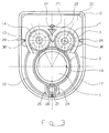
- Fig. 3 shows a further variant of the invention, in which the two Rotors 3 and 13 with their gears 4 and 14 on one common bearing element 20 are mounted, this Bearing element with two spring-elastic clamps 17 and 18 with a further bearing element for a gear 25 are connected, this gear 25 also meshes with the gear 2.
- the Gear 25 serves as a support wheel, which ensures that the gears 4th and 14 radially towards the center or the axis of rotation of the Gear 2 are pressed.
- the bearing elements 20 and 24 as well the two clamps 17 and 18 form one around the gear 2 running, closed ring body, which is preferably made of Plastic is made.
- the bearing element 20 is on a holding plate 21 along a pin 22 and an elongated hole 23 slidably held, the holding plate 21 in a housing 31st is kept displaceable, namely from the housing wall protruding pins 29 and 29 'and corresponding recesses 30 and 30 'on the plate 21.
- the bearing element 24 is over a pin 27 attached to the housing and an elongated hole 28 also kept displaceable, such that the bearing element itself only move radially towards the center of gear 2 can, however, not in the circumferential direction, so that the pins 27 and 22nd form an anti-rotation device.
- the gearwheel 2 has a tongue and groove connection 19 held in rotation on shaft 1.
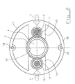
- FIG. 3A shows a plan view of a housing 31 of the Position sensor, here as a one-piece plastic injection molded part is trained.
- the housing has a frame on which the Bearing elements 20 and 24 via resilient webs 33 'and 34' and 35 'are held.
- the bearing elements 20 and 24 are also through here two spring-elastic clamps 17 and 18 connected to each other and towards the axis of the driving, not shown here Prestressed gear.
- the resilient webs 33 ', 34' and 35 ' run essentially tangential to the direction of rotation of the driving gear and are thus only in the direction of rotation on train or pressure and therefore relatively rigid, with which their function as Protection against rotation is well guaranteed. Radially towards the In contrast, they are flexible and axis of the driving gear therefore allow a displacement of the bearing elements 20 and 24 in Direction to the axis of the driving gear.
- Fig. 4 shows a variant similar to Fig. 2 with the difference that the Bearing elements 15 and 16 and the clamps 17 and 18 a little have a different shape and optionally also from several parts can be composed and then by a screw or Rivet connection (see 32) are interconnected.
- the reference number 32 can also stand for spacer bolts, which are the bearing elements support against a board.
- the clamps 17 and 18 are with their Ends each connected to ends of the bearing elements 15 and 16 and bent into segments of a circle so that they are essentially parallel to Extend the outer contour of the driving gear 2. Draw or the clamps 17 and 18 press the driven gears 4 and 14 radially to the center of the driving gear 2.
- the bearing elements 15 and 16 are each connected to two fastening arms 33, 34 and 35, 36, at the ends of which there is a pin receptacle 37 for receiving and fixation on a pin 10, which serves as an anti-rotation device.
- the mounting arms are 33-36 flexurally elastic, for a displacement of the bearing elements 15 and 16 radially to allow the center of the driving gear 2. It is also possible to fix the pin 10 firmly to the pin receptacle 37 and in one (not counter bearings for the pins, e.g. similar to a holding plate the plate 21 in Fig. 3 to provide elongated holes in which the pins slide can.
- FIG. 5 shows a modification of FIG. 4, in which the clamps 17 and 18 at the free ends of the mounting arms via the clamps 17 and 18 are connected in pairs.
- the clamp 17 connects the Fastening arms 33 and 35, the clamping bracket 18, the arms 34 and 36.
- the Clamping brackets 17 and 18 are inward towards the driver Gear 2 curved.
- the installation must be carried out in such a way that the ends of arms 33-36 are straight parallel to one the middle of the three Gears 2, 4 and 14 extending line are slidable.
- pin 10 are attached to the pin receptacle 37 and in Slots one Retaining plate, not shown, be slidably guided.
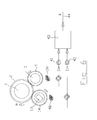
- FIG. 6 shows a basic circuit diagram of the position sensor.
- On Angle sensor for recording the absolute position, especially via several revolutions, in a special embodiment a central driver 1,2 and two differently translated Rotors 3.13, which are driven by the driver. The the exact functioning of such a system is described below described.
- the two gears 4 and 14 driven by the driving gear 2 move the rotors 3 and 13, which are magnets here. These interact with stationary parts 39, 40 of the sensor modules that generate an electrical output signal that is a function of the angle of rotation.
- the sensor modules 13.40; 3.39 can output an output signal that is linearly dependent on the angle of rotation.
- sensors which deliver a sine and a cosine output signal in a known manner, from which linear signals are then determined.
- the output signals ⁇ 1 and ⁇ 2 of the sensor modules 39 and 40 are each fed via an analog / digital converter 41 or 42 to a microprocessor 43 which evaluates and processes the signals and outputs an output signal ⁇ corresponding to the angle of rotation of shaft 1 at its output 44 .
- This signal can preferably be output in digital but also in analog form and is determined as follows:
- Both sensor modules 3.39 and 13.40 each provide a periodically repeating output signal as a function of the location (angle or path) at their outputs. After processing in the microprocessor, the respective output signals form sawtooth-shaped functions of the angle or the location.
- the output signals of the sensor modules are fed to the microprocessor 43, processed there and output at its output as a highly accurate error-corrected output signal ⁇ fine , which is linear over the entire measuring range of k 1 periods of the sensor.
- a difference signal ⁇ ⁇ 1 - ⁇ 2 is formed in a first step.
- This corrected difference signal ⁇ c can be roughly accurate, absolute Output signal over the entire path or to be evaluated View the angular range (useful range or measuring range).
- the corrected difference signal ⁇ c is therefore not arbitrarily precise or linear, but can have a certain ripple.
- the procedure is as follows. The value of the current period of the one sensor is determined from the corrected difference signal ⁇ c , ie the valid period number multiplied by 2 ⁇ , which is done by rounding or cutting to the corresponding integer in the range 0 to k1-1 and multiplication by 2 ⁇ .
- This auxiliary signal may only move in the size range from - ⁇ to + ⁇ .
- a comparison is therefore carried out to check whether the auxiliary signal is ⁇ - ⁇ . If this is the case, the fine-precise absolute output signal ⁇ f is corrected by + 2 ⁇ . If, on the other hand, the condition is not met, a comparison is made to determine whether the auxiliary signal is> ⁇ . If this is the case, the fine-precise absolute output signal ⁇ f is corrected by -2 ⁇ . If this condition is also not met, there is no period jump and the precise absolute output signal ⁇ f remains unchanged. The result then represents an error-corrected absolute output signal ⁇ fine over the entire measuring range. The evaluation shown so far is described in the older, not previously published DE patent application 198 49 554.
- the output signal ⁇ fine can still be faulty, be it due to manufacturing tolerances of the gears, in particular with regard to tooth shape and tooth pitch, or due to wear. It is also possible that when using two driven sensors according to the exemplary embodiments in FIGS. 2 to 5, a driven gear meshes with the driving gear without play while the other gear has play. To solve this problem, the invention proposes, according to a further development, such errors as a difference signal
- ⁇ is defined as As long as the phase errors occurring in the GIn. (4) and (5) are given limits, the quantity ⁇ is a linear function of the phase error, and it holds
- the jump points of ⁇ are identical to those of ⁇ fine and can be derived from the calculation rule for fine (see also the 2nd correction step in the above description of the evaluation method).
- the associated relative rotation angle error of the overall system is as in case a)
- This error signal can for example a controller (e.g. a driving dynamics controller in one Switch off the motor vehicle that is processing a steering angle signal) and / or are also output as a warning signal, to indicate that the sensor should be replaced.
- a controller e.g. a driving dynamics controller in one Switch off the motor vehicle that is processing a steering angle signal
- the invention together with the error detection measures can not only 1 to 6 are used in the rotary position sensors but also with linear position transducers, if these after the have the same functional principle.
Landscapes
- Engineering & Computer Science (AREA)
- Physics & Mathematics (AREA)
- General Physics & Mathematics (AREA)
- Chemical & Material Sciences (AREA)
- Combustion & Propulsion (AREA)
- Transportation (AREA)
- Mechanical Engineering (AREA)
- Length Measuring Devices With Unspecified Measuring Means (AREA)
- Measurement Of Length, Angles, Or The Like Using Electric Or Magnetic Means (AREA)
Applications Claiming Priority (2)
| Application Number | Priority Date | Filing Date | Title |
|---|---|---|---|
| DE19962241 | 1999-12-22 | ||
| DE19962241A DE19962241A1 (de) | 1999-12-22 | 1999-12-22 | Positionssensor |
Publications (2)
| Publication Number | Publication Date |
|---|---|
| EP1132716A1 true EP1132716A1 (fr) | 2001-09-12 |
| EP1132716B1 EP1132716B1 (fr) | 2007-05-09 |
Family
ID=7933958
Family Applications (1)
| Application Number | Title | Priority Date | Filing Date |
|---|---|---|---|
| EP00127776A Expired - Lifetime EP1132716B1 (fr) | 1999-12-22 | 2000-12-19 | Capteur de position |
Country Status (3)
| Country | Link |
|---|---|
| US (1) | US6552533B2 (fr) |
| EP (1) | EP1132716B1 (fr) |
| DE (2) | DE19962241A1 (fr) |
Cited By (5)
| Publication number | Priority date | Publication date | Assignee | Title |
|---|---|---|---|---|
| DE102006023286A1 (de) * | 2006-05-18 | 2007-11-22 | Leopold Kostal Gmbh & Co. Kg | Winkelsensor |
| DE102008063951A1 (de) | 2008-12-19 | 2010-06-24 | Leopold Kostal Gmbh & Co. Kg | Winkelsensor |
| WO2010122114A1 (fr) | 2009-04-24 | 2010-10-28 | Leopold Kostal Gmbh & Co. Kg | Capteur angulaire |
| WO2011161113A2 (fr) | 2010-06-23 | 2011-12-29 | Leopold Kostal Gmbh & Co. Kg | Capteur d'angle |
| WO2016041975A1 (fr) * | 2014-09-17 | 2016-03-24 | Continental Teves Ag & Co. Ohg | Capteur d'angle de braquage doté d'un entraînement sans jeu |
Families Citing this family (50)
| Publication number | Priority date | Publication date | Assignee | Title |
|---|---|---|---|---|
| DE10390447B4 (de) * | 2002-02-06 | 2012-09-20 | Haldex Brake Products Ab | Digitaler Sensor |
| JP4209155B2 (ja) * | 2002-03-05 | 2009-01-14 | アルプス電気株式会社 | 回転角検出装置 |
| RU2328015C2 (ru) * | 2002-07-26 | 2008-06-27 | Роберт Бош Гмбх | Чувствительный элемент с гигантской магниторезистивностью и его применение |
| JP2004184264A (ja) * | 2002-12-04 | 2004-07-02 | Matsushita Electric Ind Co Ltd | 回転角度検出装置 |
| DE10334869B3 (de) * | 2003-07-29 | 2004-09-16 | Tech3 E.K. | Drehwinkelsensor |
| JP2005077305A (ja) * | 2003-09-02 | 2005-03-24 | Matsushita Electric Ind Co Ltd | 回転角度およびトルク検出装置 |
| JP2005114481A (ja) * | 2003-10-06 | 2005-04-28 | Yazaki Corp | 回転角センサ |
| US6941207B2 (en) * | 2003-10-10 | 2005-09-06 | Matsushita Electric Industrial Co., Ltd. | Steering angular velocity detecting device |
| DE102004021405A1 (de) * | 2003-12-03 | 2005-07-07 | Valeo Schalter Und Sensoren Gmbh | Lenksäulenmodul |
| US7625379B2 (en) * | 2004-01-26 | 2009-12-01 | Warsaw Orthopedic, Inc. | Methods and instrumentation for inserting intervertebral grafts and devices |
| JP4518833B2 (ja) * | 2004-02-03 | 2010-08-04 | 矢崎総業株式会社 | 回転角センサ |
| US7174795B2 (en) * | 2004-02-06 | 2007-02-13 | Delphi Technologies, Inc. | Integrated non-contacting torque and absolute position sensor for steering applications |
| ITTO20040168A1 (it) * | 2004-03-15 | 2004-06-15 | Skf Ab | Attuatore elettromeccanico lineare per un impianto sterzante di un veicolo a motore |
| US7191759B2 (en) * | 2004-04-09 | 2007-03-20 | Ksr Industrial Corporation | Inductive sensor for vehicle electronic throttle control |
| DE102004017692A1 (de) * | 2004-04-10 | 2005-11-10 | Moeller Gmbh | Verfahren zum Betreiben eines mechanisch-elektronischen Positionsgebers |
| DE102004017950B3 (de) | 2004-04-14 | 2005-06-23 | Moeller Gmbh | Mechanisch-elektronischer Positionsgeber |
| DE102005001077A1 (de) | 2005-01-08 | 2006-07-20 | Leopold Kostal Gmbh & Co. Kg | Verfahren zum Korrigieren aus Messwerten abgeleiteter Kennlinien eines magnetoresistiv ausgelegten Weg- oder Winkelsensors |
| JP4432809B2 (ja) * | 2005-03-17 | 2010-03-17 | パナソニック株式会社 | 回転角度検出装置 |
| US7292026B2 (en) * | 2005-04-08 | 2007-11-06 | Ksr International Co. | Signal conditioning system for inductive position sensor |
| JP2006329748A (ja) * | 2005-05-25 | 2006-12-07 | Ge Medical Systems Global Technology Co Llc | ポテンショメータ |
| US7449878B2 (en) | 2005-06-27 | 2008-11-11 | Ksr Technologies Co. | Linear and rotational inductive position sensor |
| JP2007139741A (ja) * | 2005-10-20 | 2007-06-07 | Matsushita Electric Ind Co Ltd | 回転角度検出装置 |
| DE102005057229B3 (de) * | 2005-11-29 | 2007-05-31 | Sick Stegmann Gmbh | Vorrichtung zur absoluten Messung der linearen oder rotatorischen Position eines Messobjektes |
| DE102005058131A1 (de) | 2005-11-30 | 2007-06-06 | Valeo Schalter Und Sensoren Gmbh | Lenkwinkelsensor |
| JP2007285799A (ja) * | 2006-04-14 | 2007-11-01 | Matsushita Electric Ind Co Ltd | 回転角度検出装置 |
| JP4992516B2 (ja) * | 2007-04-02 | 2012-08-08 | パナソニック株式会社 | 回転角度検出装置 |
| DE202008004480U1 (de) | 2008-04-02 | 2009-08-13 | Krones Ag | Halteeinrichtung für Drehimpulsgeber |
| DE102008020548A1 (de) * | 2008-04-24 | 2009-10-29 | Continental Teves Ag & Co. Ohg | Encoderanordnung für eine vereinfachte Montage auf einer Welle |
| DE102008042596A1 (de) * | 2008-10-02 | 2010-04-08 | Zf Friedrichshafen Ag | Vorrichtung zur Erfassung einer Winkelposition einer Steuerwelle |
| JP4893721B2 (ja) * | 2008-10-06 | 2012-03-07 | トヨタ自動車株式会社 | 回転角検出装置 |
| DE102010033769A1 (de) | 2010-08-09 | 2012-02-09 | Valeo Schalter Und Sensoren Gmbh | Vorrichtung mit einem Drehmomentsensor und einem Drehwinkelsensor |
| DE102010052949A1 (de) * | 2010-11-30 | 2012-05-31 | Valeo Schalter Und Sensoren Gmbh | Vorrichtung zum Erfassen eines Positionswinkels eines drehbaren Bauteils eines Fahrzeugs sowie Fahrzeug mit einer derartigen Vorrichtung |
| DE102011103576A1 (de) | 2011-05-30 | 2012-12-06 | Megamotive Gmbh & Co. Kg | Drehwinkelsensor |
| DE102011052043B4 (de) | 2011-07-21 | 2022-06-09 | Bourns, Inc. | Drehwinkel- und Torsionswinkelsensor |
| DE102011118928B4 (de) | 2011-11-21 | 2017-12-07 | Bourns, Inc. | Drehwinkelsensor |
| DE102011122341A1 (de) * | 2011-12-23 | 2013-06-27 | Valeo Schalter Und Sensoren Gmbh | Zahnrad für eine Vorrichtung zum Erfassen eines Positionswinkels eines drehbaren Bauteils eines Fahrzeugs, Vorrichtung mit einem derartigen Zahnrad sowie Fahrzeug mit einer entsprechenden Vorrichtung |
| US20130257419A1 (en) * | 2012-03-27 | 2013-10-03 | Be Aerospace, Inc. | Magnetic encoder system for aircraft seating actuator |
| DE102012109787B4 (de) | 2012-10-15 | 2014-05-15 | Takata AG | Lenkwinkelsensor für Kraftfahrzeuge |
| EP3832169A1 (fr) * | 2012-10-31 | 2021-06-09 | Parker-Hannifin Corporation | Système de commande d'engrenage pour atténuer les vibrations |
| DE102012022869A1 (de) | 2012-11-21 | 2014-05-22 | Volkswagen Aktiengesellschaft | Lenkwinkelsensor und Vorrichtung zur kombinierten Erfassung von einem Winkel und einem Drehmoment |
| DE102012024383A1 (de) | 2012-12-13 | 2014-06-18 | Valeo Schalter Und Sensoren Gmbh | Vorrichtung mit einer Drehmomentsensoreinrichtung und einer Lenkwinkelsensoreinrichtung für ein Kraftfahrzeug, Kraftfahrzeug und Verfahren zum Herstellen einer Vorrichtung |
| DE102012024382A1 (de) | 2012-12-13 | 2014-06-18 | Valeo Schalter Und Sensoren Gmbh | Vorrichtung mit einer Drehmomentsensoreinrichtung und optional einer Lenkwinkelsensoreinrichtung für ein Kraftfahrzeug, Kraftfahrzeug und Verfahren zum Herstellen einer Drehmomentsensoreinrichtung |
| USD712768S1 (en) * | 2013-04-24 | 2014-09-09 | Cateye Co., Ltd. | Rotation detector for a bicycle |
| DE102013019787A1 (de) | 2013-11-27 | 2015-05-28 | Valeo Schalter Und Sensoren Gmbh | Verfahren zum Herstellen eines ferromagnetischen Bauteils für einen Drehmomentsensor einer Fahrzeuglenkwelle und Drehmomentsensor |
| DE102015115686B4 (de) * | 2015-09-17 | 2022-11-17 | Bourns, Inc. | Lenkwinkelsensor mit funktioneller Sicherheit |
| DE102016124370A1 (de) | 2016-12-14 | 2018-06-14 | Valeo Schalter Und Sensoren Gmbh | Sensorvorrichtung sowie Verfahren zum Zusammenbau einer Sensorvorrichtung |
| DE102017116454A1 (de) | 2017-07-21 | 2019-01-24 | Valeo Schalter Und Sensoren Gmbh | Sensorvorrichtung |
| WO2019149369A1 (fr) * | 2018-02-02 | 2019-08-08 | Thyssenkrupp Presta Ag | Surveillance de la stabilité du temps d'exécution d'un capteur d'angle de braquage sur la base d'un principe de nonius |
| JP7293660B2 (ja) * | 2019-01-18 | 2023-06-20 | 株式会社ジェイテクト | 回転角検出装置 |
| CN110174149B (zh) * | 2019-06-18 | 2024-07-09 | 台州杜瑞仪表有限公司 | 煤气表计量温度补偿装置 |
Citations (2)
| Publication number | Priority date | Publication date | Assignee | Title |
|---|---|---|---|---|
| DE2849918A1 (de) * | 1978-01-24 | 1979-07-26 | Ackeret Design & Eng | Digitale optische anzeigeeinrichtung fuer die position eines messorgans |
| DE19506938A1 (de) * | 1995-02-28 | 1996-08-29 | Bosch Gmbh Robert | Verfahren und Vorrichtung zur Winkelmessung bei einem drehbaren Körper |
Family Cites Families (4)
| Publication number | Priority date | Publication date | Assignee | Title |
|---|---|---|---|---|
| DE3900270A1 (de) | 1989-01-07 | 1990-07-12 | Heidelberger Druckmasch Ag | Vorrichtung zur positionserfassung |
| FR2697081B1 (fr) | 1992-10-21 | 1995-01-06 | Rockwell Abs France | Codeur à large étendue de mesure, destiné à la détermination de la position d'une pièce dans une course d'amplitude prédéterminée, telle qu'un accessoire de véhicule. |
| FR2764058B1 (fr) * | 1997-06-03 | 1999-07-02 | Skf France | Dispositif de detection pour colonne de direction |
| DE19747753C1 (de) | 1997-10-29 | 1999-05-12 | Ruf Electronics Gmbh | Verfahren zum Ermitteln des Phasenwinkels bei Positionsgebern mit sinusförmigen Ausgangssignalen |
-
1999
- 1999-12-22 DE DE19962241A patent/DE19962241A1/de not_active Withdrawn
-
2000
- 2000-12-19 EP EP00127776A patent/EP1132716B1/fr not_active Expired - Lifetime
- 2000-12-19 DE DE50014319T patent/DE50014319D1/de not_active Expired - Lifetime
- 2000-12-22 US US09/747,632 patent/US6552533B2/en not_active Expired - Lifetime
Patent Citations (2)
| Publication number | Priority date | Publication date | Assignee | Title |
|---|---|---|---|---|
| DE2849918A1 (de) * | 1978-01-24 | 1979-07-26 | Ackeret Design & Eng | Digitale optische anzeigeeinrichtung fuer die position eines messorgans |
| DE19506938A1 (de) * | 1995-02-28 | 1996-08-29 | Bosch Gmbh Robert | Verfahren und Vorrichtung zur Winkelmessung bei einem drehbaren Körper |
Cited By (15)
| Publication number | Priority date | Publication date | Assignee | Title |
|---|---|---|---|---|
| DE102006023286A1 (de) * | 2006-05-18 | 2007-11-22 | Leopold Kostal Gmbh & Co. Kg | Winkelsensor |
| WO2007134801A3 (fr) * | 2006-05-18 | 2008-01-17 | Kostal Leopold Gmbh & Co Kg | Capteur angulaire |
| US7765702B2 (en) | 2006-05-18 | 2010-08-03 | Leopold Kostal Gmbh & Co. Kg | Angle sensor |
| DE102008063951A1 (de) | 2008-12-19 | 2010-06-24 | Leopold Kostal Gmbh & Co. Kg | Winkelsensor |
| WO2010070014A1 (fr) * | 2008-12-19 | 2010-06-24 | Leopold Kostal Gmbh & Co. Kg | Détecteur de position angulaire |
| DE102009018893A1 (de) | 2009-04-24 | 2010-10-28 | Leopold Kostal Gmbh & Co. Kg | Winkelsensor |
| WO2010122114A1 (fr) | 2009-04-24 | 2010-10-28 | Leopold Kostal Gmbh & Co. Kg | Capteur angulaire |
| US8570031B2 (en) | 2009-04-24 | 2013-10-29 | Leopold Kostal Gmbh & Co. Kg | Angle sensor |
| WO2011161113A2 (fr) | 2010-06-23 | 2011-12-29 | Leopold Kostal Gmbh & Co. Kg | Capteur d'angle |
| DE102010024782A1 (de) | 2010-06-23 | 2011-12-29 | Leopold Kostal Gmbh & Co. Kg | Winkelsensor |
| CN103038607A (zh) * | 2010-06-23 | 2013-04-10 | 利奥波德·科世达责任有限股份公司 | 角度传感器 |
| US8963543B2 (en) | 2010-06-23 | 2015-02-24 | Leopold Kostal Gmbh & Co. Kg | Angle sensor for sensing angular position of a rotatable shaft |
| WO2016041975A1 (fr) * | 2014-09-17 | 2016-03-24 | Continental Teves Ag & Co. Ohg | Capteur d'angle de braquage doté d'un entraînement sans jeu |
| CN107074278A (zh) * | 2014-09-17 | 2017-08-18 | 大陆-特韦斯股份有限公司 | 具有无间隙的驱动装置的sas |
| CN107074278B (zh) * | 2014-09-17 | 2020-01-31 | 大陆-特韦斯股份有限公司 | 具有无间隙的驱动装置的sas |
Also Published As
| Publication number | Publication date |
|---|---|
| US20030056583A1 (en) | 2003-03-27 |
| US6552533B2 (en) | 2003-04-22 |
| EP1132716B1 (fr) | 2007-05-09 |
| DE50014319D1 (de) | 2007-06-21 |
| DE19962241A1 (de) | 2001-07-12 |
Similar Documents
| Publication | Publication Date | Title |
|---|---|---|
| EP1132716B1 (fr) | Capteur de position | |
| EP1141660B1 (fr) | Dispositif et procede pour la mesure de la position angulaire d'un corps rotatif | |
| EP1238891B1 (fr) | Capteur de l'angle de braquage | |
| EP3368393B1 (fr) | Dispositif de direction assistée électroméchanique, procédé de calcul d'un angle de braquage absolu et procédé de calibration d'un dispositif de mésure de l'angle absolu de braquage | |
| EP1313999B1 (fr) | Procede et dispositif de mesure d'angles | |
| EP1315954B1 (fr) | Procede pour determiner une difference angulaire a partir de signaux de mise en phase | |
| EP2225142B1 (fr) | Arrangement de detection de l'angle de direction a mesure absolue | |
| DE10334869B3 (de) | Drehwinkelsensor | |
| EP1102971B1 (fr) | Systeme detecteur permettant de detecter un angle de rotation et/ou un couple de rotation | |
| EP2782810B1 (fr) | Capteur d'angle de rotation | |
| DE112010005022B4 (de) | Relativwinkel-Detektionsvorrichtung, Drehwinkel-Detektionsvorrichtung, Relativwinkel-Detektionsverfahren und Drehwinkel-Detektionsverfahren | |
| DE19506938A1 (de) | Verfahren und Vorrichtung zur Winkelmessung bei einem drehbaren Körper | |
| DE102012109787B4 (de) | Lenkwinkelsensor für Kraftfahrzeuge | |
| EP1314004A1 (fr) | Procede de correction de mesures d'angles a l'aide d'au moins deux pistes de code | |
| DE102020106785A1 (de) | Hinterachslenkung und Lenkwinkelmessung an der Hinterachse eines Kraftfahrzeugs | |
| EP2018518A2 (fr) | Capteur angulaire | |
| EP1925533B1 (fr) | Capteur d'angle de rotation et de couple combiné | |
| DE102020108981A1 (de) | Sensoranordnung zur Erfassung der absoluten Winkelposition eines Lenkelements | |
| DE102012202657A1 (de) | Sensoranordnung zur Erfassung von Drehwinkeln an einem rotierenden Bauteil in einem Fahrzeug | |
| DE19834322B4 (de) | Verfahren und Vorrichtung zur Ermittlung des auf eine Welle wirkenden Drehmoments | |
| DE102015209425A1 (de) | Sensoranordnung zur Erfassung von Drehwinkeln an einem rotierenden Bauteil in einem Fahrzeug | |
| DE10348914B4 (de) | Vorrichtung zum Messen des Drehwinkels eines Drehkörpers | |
| DE102020108982A1 (de) | Sensoranordnung mit einem vollständig redundanten Messsystem zur Erfassung der absoluten Winkelposition eines Lenkelements | |
| DE102004063415A1 (de) | Drehwinkel-Detektionsvorrichtung und Drehmoment-Detektionsvorrichtung | |
| DE102023208941A1 (de) | Vorrichtung zur Messung eines absoluten Drehwinkels eines drehbar gelagerten Elements |
Legal Events
| Date | Code | Title | Description |
|---|---|---|---|
| PUAI | Public reference made under article 153(3) epc to a published international application that has entered the european phase |
Free format text: ORIGINAL CODE: 0009012 |
|
| AK | Designated contracting states |
Kind code of ref document: A1 Designated state(s): AT BE CH CY DE DK ES FI FR GB GR IE IT LI LU MC NL PT SE TR Kind code of ref document: A1 Designated state(s): DE FR GB IT |
|
| AX | Request for extension of the european patent |
Free format text: AL;LT;LV;MK;RO;SI |
|
| 17P | Request for examination filed |
Effective date: 20020301 |
|
| AKX | Designation fees paid |
Free format text: DE FR GB IT |
|
| RAP1 | Party data changed (applicant data changed or rights of an application transferred) |
Owner name: RUF AUTOMOTIVE GMBH |
|
| 17Q | First examination report despatched |
Effective date: 20050218 |
|
| RAP1 | Party data changed (applicant data changed or rights of an application transferred) |
Owner name: BOURNS, INC. |
|
| GRAP | Despatch of communication of intention to grant a patent |
Free format text: ORIGINAL CODE: EPIDOSNIGR1 |
|
| GRAS | Grant fee paid |
Free format text: ORIGINAL CODE: EPIDOSNIGR3 |
|
| GRAA | (expected) grant |
Free format text: ORIGINAL CODE: 0009210 |
|
| AK | Designated contracting states |
Kind code of ref document: B1 Designated state(s): DE FR GB IT |
|
| REG | Reference to a national code |
Ref country code: GB Ref legal event code: FG4D Free format text: NOT ENGLISH |
|
| REF | Corresponds to: |
Ref document number: 50014319 Country of ref document: DE Date of ref document: 20070621 Kind code of ref document: P |
|
| GBT | Gb: translation of ep patent filed (gb section 77(6)(a)/1977) |
Effective date: 20070820 |
|
| ET | Fr: translation filed | ||
| PLBE | No opposition filed within time limit |
Free format text: ORIGINAL CODE: 0009261 |
|
| STAA | Information on the status of an ep patent application or granted ep patent |
Free format text: STATUS: NO OPPOSITION FILED WITHIN TIME LIMIT |
|
| 26N | No opposition filed |
Effective date: 20080212 |
|
| REG | Reference to a national code |
Ref country code: FR Ref legal event code: PLFP Year of fee payment: 16 |
|
| REG | Reference to a national code |
Ref country code: FR Ref legal event code: PLFP Year of fee payment: 17 |
|
| REG | Reference to a national code |
Ref country code: FR Ref legal event code: PLFP Year of fee payment: 18 |
|
| PGFP | Annual fee paid to national office [announced via postgrant information from national office to epo] |
Ref country code: FR Payment date: 20191219 Year of fee payment: 20 Ref country code: IT Payment date: 20191216 Year of fee payment: 20 |
|
| PGFP | Annual fee paid to national office [announced via postgrant information from national office to epo] |
Ref country code: GB Payment date: 20191210 Year of fee payment: 20 Ref country code: DE Payment date: 20200212 Year of fee payment: 20 |
|
| REG | Reference to a national code |
Ref country code: DE Ref legal event code: R071 Ref document number: 50014319 Country of ref document: DE |
|
| REG | Reference to a national code |
Ref country code: GB Ref legal event code: PE20 Expiry date: 20201218 |
|
| PG25 | Lapsed in a contracting state [announced via postgrant information from national office to epo] |
Ref country code: GB Free format text: LAPSE BECAUSE OF EXPIRATION OF PROTECTION Effective date: 20201218 |