EP1134100A2 - Aufhängungssystem mit rotierenden Dämpfungsmitteln - Google Patents
Aufhängungssystem mit rotierenden Dämpfungsmitteln Download PDFInfo
- Publication number
- EP1134100A2 EP1134100A2 EP01830130A EP01830130A EP1134100A2 EP 1134100 A2 EP1134100 A2 EP 1134100A2 EP 01830130 A EP01830130 A EP 01830130A EP 01830130 A EP01830130 A EP 01830130A EP 1134100 A2 EP1134100 A2 EP 1134100A2
- Authority
- EP
- European Patent Office
- Prior art keywords
- arms
- suspension
- shock
- axis
- suspension system
- Prior art date
- Legal status (The legal status is an assumption and is not a legal conclusion. Google has not performed a legal analysis and makes no representation as to the accuracy of the status listed.)
- Withdrawn
Links
Images


Classifications
-
- B—PERFORMING OPERATIONS; TRANSPORTING
- B60—VEHICLES IN GENERAL
- B60G—VEHICLE SUSPENSION ARRANGEMENTS
- B60G21/00—Interconnection systems for two or more resiliently-suspended wheels, e.g. for stabilising a vehicle body with respect to acceleration, deceleration or centrifugal forces
- B60G21/02—Interconnection systems for two or more resiliently-suspended wheels, e.g. for stabilising a vehicle body with respect to acceleration, deceleration or centrifugal forces permanently interconnected
- B60G21/04—Interconnection systems for two or more resiliently-suspended wheels, e.g. for stabilising a vehicle body with respect to acceleration, deceleration or centrifugal forces permanently interconnected mechanically
- B60G21/05—Interconnection systems for two or more resiliently-suspended wheels, e.g. for stabilising a vehicle body with respect to acceleration, deceleration or centrifugal forces permanently interconnected mechanically between wheels on the same axle but on different sides of the vehicle, i.e. the left and right wheel suspensions being interconnected
- B60G21/051—Trailing arm twist beam axles
-
- B—PERFORMING OPERATIONS; TRANSPORTING
- B60—VEHICLES IN GENERAL
- B60G—VEHICLE SUSPENSION ARRANGEMENTS
- B60G13/00—Resilient suspensions characterised by arrangement, location or type of vibration dampers
- B60G13/02—Resilient suspensions characterised by arrangement, location or type of vibration dampers having dampers dissipating energy, e.g. frictionally
- B60G13/06—Resilient suspensions characterised by arrangement, location or type of vibration dampers having dampers dissipating energy, e.g. frictionally of fluid type
- B60G13/08—Resilient suspensions characterised by arrangement, location or type of vibration dampers having dampers dissipating energy, e.g. frictionally of fluid type hydraulic
-
- B—PERFORMING OPERATIONS; TRANSPORTING
- B60—VEHICLES IN GENERAL
- B60G—VEHICLE SUSPENSION ARRANGEMENTS
- B60G15/00—Resilient suspensions characterised by arrangement, location or type of combined spring and vibration damper, e.g. telescopic type
- B60G15/02—Resilient suspensions characterised by arrangement, location or type of combined spring and vibration damper, e.g. telescopic type having mechanical spring
- B60G15/06—Resilient suspensions characterised by arrangement, location or type of combined spring and vibration damper, e.g. telescopic type having mechanical spring and fluid damper
-
- B—PERFORMING OPERATIONS; TRANSPORTING
- B60—VEHICLES IN GENERAL
- B60G—VEHICLE SUSPENSION ARRANGEMENTS
- B60G21/00—Interconnection systems for two or more resiliently-suspended wheels, e.g. for stabilising a vehicle body with respect to acceleration, deceleration or centrifugal forces
- B60G21/02—Interconnection systems for two or more resiliently-suspended wheels, e.g. for stabilising a vehicle body with respect to acceleration, deceleration or centrifugal forces permanently interconnected
- B60G21/04—Interconnection systems for two or more resiliently-suspended wheels, e.g. for stabilising a vehicle body with respect to acceleration, deceleration or centrifugal forces permanently interconnected mechanically
- B60G21/05—Interconnection systems for two or more resiliently-suspended wheels, e.g. for stabilising a vehicle body with respect to acceleration, deceleration or centrifugal forces permanently interconnected mechanically between wheels on the same axle but on different sides of the vehicle, i.e. the left and right wheel suspensions being interconnected
- B60G21/051—Trailing arm twist beam axles
- B60G21/052—Mounting means therefor
-
- B—PERFORMING OPERATIONS; TRANSPORTING
- B60—VEHICLES IN GENERAL
- B60G—VEHICLE SUSPENSION ARRANGEMENTS
- B60G2202/00—Indexing codes relating to the type of spring, damper or actuator
- B60G2202/10—Type of spring
- B60G2202/13—Torsion spring
- B60G2202/136—Twist-beam type arrangement
-
- B—PERFORMING OPERATIONS; TRANSPORTING
- B60—VEHICLES IN GENERAL
- B60G—VEHICLE SUSPENSION ARRANGEMENTS
- B60G2202/00—Indexing codes relating to the type of spring, damper or actuator
- B60G2202/20—Type of damper
- B60G2202/22—Rotary Damper
-
- B—PERFORMING OPERATIONS; TRANSPORTING
- B60—VEHICLES IN GENERAL
- B60G—VEHICLE SUSPENSION ARRANGEMENTS
- B60G2204/00—Indexing codes related to suspensions per se or to auxiliary parts
- B60G2204/10—Mounting of suspension elements
- B60G2204/12—Mounting of springs or dampers
- B60G2204/122—Mounting of torsion springs
-
- B—PERFORMING OPERATIONS; TRANSPORTING
- B60—VEHICLES IN GENERAL
- B60G—VEHICLE SUSPENSION ARRANGEMENTS
- B60G2204/00—Indexing codes related to suspensions per se or to auxiliary parts
- B60G2204/10—Mounting of suspension elements
- B60G2204/12—Mounting of springs or dampers
- B60G2204/128—Damper mount on vehicle body or chassis
-
- B—PERFORMING OPERATIONS; TRANSPORTING
- B60—VEHICLES IN GENERAL
- B60G—VEHICLE SUSPENSION ARRANGEMENTS
- B60G2204/00—Indexing codes related to suspensions per se or to auxiliary parts
- B60G2204/10—Mounting of suspension elements
- B60G2204/12—Mounting of springs or dampers
- B60G2204/129—Damper mount on wheel suspension or knuckle
Definitions
- the present invention relates to mechanical suspensions, for example for motor vehicles, of the type comprising:
- Suspensions for motor vehicles, in particular rear suspensions, of the type specified above are known and have been used for some time in various versions which utilize both longitudinal arms, i.e. arms that are arranged substantially parallel to the longitudinal plane of the motor vehicle and are articulated about an axis that is transverse to said plane, and transverse arms, again with respect to the longitudinal direction of the motor vehicle, which are articulated about respective longitudinal axes, as well as oblique arms, namely arms arranged according to directions which are inclined both with respect to the longitudinal direction and with respect to a direction orthogonal to the longitudinal direction.
- elastic means in the form of torsion bars Likewise known for some time is the use of elastic means in the form of torsion bars. The latter solution presents the advantage of a reduced bulk, as compared to the other conventional solution involving the use of helical springs arranged above the arms.
- the subject of the present invention is a suspension having the known characteristics referred to above and being further characterized in that the aforesaid shock-absorbing means are made up of two rotational shock absorbers which are respectively associated to the two arms of the suspension and each of which includes:
- each of the two aforesaid rotational shock absorbers is of the type that forms the subject of the previous Italian Patent Application TO99A000643 filed by the present applicant on July 20, 1999 and still secret at the priority date of the present application.
- each of the rotational shock absorbers forming part of the suspension according to the invention is characterized in that said shock-absorbing fluid is a magnetorheological or electrorheological fluid, and an electrically controlled excitation device is arranged in a position corresponding to said passage for controlling the resistance of outflow of the fluid that traverses the said passage.
- Magnetorheological or electrorheological fluid compositions undergo a variation in apparent viscosity in the presence of a magnetic field or of an electric field.
- Magnetorheological fluids usually comprise ferromagnetic and paramagnetic particles, typically with diameters of the order of 1-10 micron, dispersed in a carrier fluid.
- the particles In the presence of a magnetic field, the particles are polarized and organize themselves into chains of particles inside the fluid. The chains of particles operate in such a way as to increase the apparent viscosity or global outflow resistance of the fluid.
- the particles return to a free, i.e., non-organized state, and the apparent viscosity or outflow resistance of the material is reduced accordingly.
- Magnetorheological materials present a controllable behaviour similar to the one observed for electrorheological materials, which respond to an electric field instead of to a magnetic field. Both electrorheological materials and magnetorheological materials are useful for providing variable damping forces inside devices such as shock absorbers.
- the magnetorheological shock absorbers of the more conventional type are typically of the cylinder-and-plunger type. These shock absorbers have relatively high working pressures (in the region of 30 bar) and must be equipped with seals on the stem. Magnetorheological or electrorheological fluids are abrasive, and the shock absorbers that use these fluids tend to present problems of leakage.
- the magnetorheological rotational shock absorber is of the type that has already formed the subject of the previous patent application referred to above.
- a rotational shock absorber of this type the working pressure is substantially reduced as compared to a cylinder-and-plunger shock absorber having equal characteristics (for example, a pressure of 10 bar instead of 30 bar), with the result that there is a lower risk of leakage of fluid.
- a further advantage of the magnetorheological rotational shock absorber is that the fluid is subject to lower outflow rates than those of cylinder-and-plunger shock absorbers, and this makes it possible to govern the damping characteristics with greater precision and ease.
- the suspension according to the invention may be built either with longitudinal arms or with transverse arms, or yet again with oblique arms.
- reference number 1 generally designates a rear suspension for motor vehicles, comprising two longitudinal arms 2, each having one end 3 articulated to the structure 4 of the motor vehicle about an axis 20 which is transverse with respect to the longitudinal direction of the motor vehicle (in Figure 1, the direction of advance of the motor vehicle is indicated by the arrow A).
- the rear end, designated by 5, of each arm 2 is designed to carry a respective wheel of the motor vehicle (not illustrated) about an axis 6.
- the two front ends of the longitudinal arms 2 are rigidly connected to the outer ends of two torsion bars 7 which are set along the transverse axis 20 of articulation of the longitudinal arms 2 and have their inner ends 7b rigidly connected to the structure of the motor vehicle in such a way as to act as elastic means designed to bring the two respective longitudinal arms 2 back into their resting position.
- the shock-absorbing action is exerted by two magnetorheological rotational shock absorbers 8, each built according to the teachings of the previous patent application filed by the present applicant, already cited hereinbefore.
- Each of the magnetorheological rotational shock absorbers 8 comprises a casing 9 connected, by means of screws 10, to the structure 4 of the motor vehicle (see Figure 2) and defining, within it, a chamber 11 (see Figure 3) and an outlet with a magnetorheological shock-absorbing fluid. Inside the chamber 11 there moves a plate 12 which divides the chamber 11 into two sections and which is mounted oscillating about the same transverse axis 20 of oscillation of the longitudinal arms 2 and is rigidly connected to the respective arm 2.
- the plate 12 is mounted on a hub 13 which is rigidly connected to the respective arm 2 and within which there passes the respective torsion bar 7, which has one end 7a rigidly connected to the respective arm, and the other end 7b (see again Figure 2) connected to the structure 4 of the motor vehicle.
- the plate 11 has two annular passages 14 for the seepage of the shock-absorbing fluid that occurs following upon oscillations of the plate 12.
- a field coil 15 Set coaxially inside each annular passage 14 is a field coil 15 designed to create a magnetic field which determines the passage of the magnetorheological fluid from its higher-viscosity condition to its lower-viscosity condition according to what was illustrated previously.
- each shock absorber could be different from the ones illustrated herein purely by way of example.
- the said shock absorbers could also not be of a magnetorheological type and could, instead, exploit any other means (for example, regulatable valves) for varying the damping capacity.
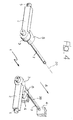
- Figure 4 illustrates a variant in which the suspension arms are set so that they are transverse to the longitudinal plane of the motor vehicle and are articulated about mutually parallel longitudinal axes which coincide with the axes of the respective torsion bars.
- the same reference numbers have been used to designate the parts that correspond to the ones in Figure 1.
- each shock absorber 8 is rigidly connected to the respective suspension arm, whilst the oscillating plate 12 is rigidly connected to the structure of the motor vehicle.
Landscapes
- Engineering & Computer Science (AREA)
- Mechanical Engineering (AREA)
- Springs (AREA)
- Vibration Dampers (AREA)
- Fluid-Damping Devices (AREA)
- Vehicle Body Suspensions (AREA)
Applications Claiming Priority (2)
| Application Number | Priority Date | Filing Date | Title |
|---|---|---|---|
| IT2000TO000254A IT1319974B1 (it) | 2000-03-17 | 2000-03-17 | Componente a cinematica rotazionale integrante funzioni di molla edammortizzatore. |
| ITTO200254 | 2000-03-17 |
Publications (2)
| Publication Number | Publication Date |
|---|---|
| EP1134100A2 true EP1134100A2 (de) | 2001-09-19 |
| EP1134100A3 EP1134100A3 (de) | 2004-05-12 |
Family
ID=11457594
Family Applications (1)
| Application Number | Title | Priority Date | Filing Date |
|---|---|---|---|
| EP01830130A Withdrawn EP1134100A3 (de) | 2000-03-17 | 2001-02-23 | Aufhängungssystem mit rotierenden Dämpfungsmitteln |
Country Status (2)
| Country | Link |
|---|---|
| EP (1) | EP1134100A3 (de) |
| IT (1) | IT1319974B1 (de) |
Cited By (6)
| Publication number | Priority date | Publication date | Assignee | Title |
|---|---|---|---|---|
| GB2382638A (en) * | 2001-11-30 | 2003-06-04 | Visteon Global Tech Inc | A magneto-rheological fluid-controlled vehicle suspension damper |
| EP1380768A2 (de) | 2002-07-09 | 2004-01-14 | C.R.F. Società Consortile per Azioni | Fahrzeugaufhängungssystem mit rotierendem Dämpfer |
| US8083245B2 (en) | 2008-06-25 | 2011-12-27 | Hatzikakidis Dimitrios A | Parametric chassis system for vehicles, comprising four suspension elements, incorporating a lateral torsion bar and co-axial damper unit, in a box-module, that allows central location of heavy items, such as batteries |
| DE102010039245A1 (de) * | 2010-08-12 | 2012-02-16 | Zf Friedrichshafen Ag | Verbundlenkerachse für ein Fahrzeug |
| EP2990685A1 (de) * | 2014-08-26 | 2016-03-02 | Canyon Bicycles GmbH | Fahrradelement |
| CN115056619A (zh) * | 2022-06-30 | 2022-09-16 | 重庆宙达机器人科技有限公司 | 一种可调节的电磁悬挂台车 |
Family Cites Families (5)
| Publication number | Priority date | Publication date | Assignee | Title |
|---|---|---|---|---|
| FR1431287A (fr) * | 1964-06-26 | 1966-03-11 | Ford France | Dispositif de suspension arrière pour véhicule à moteur |
| FR2608518B1 (fr) * | 1986-12-22 | 1991-05-31 | Aerospatiale | Suspension a bras oscillants pour un train de deux roues d'un vehicule et systeme unitaire de suspension et d'amortissement pour une telle suspension |
| US5005859A (en) * | 1988-11-18 | 1991-04-09 | Kabushiki Kaisha Showa Seisakusho | Motor vehicle suspension with rotary damper |
| DE4015777C2 (de) * | 1989-05-19 | 1997-12-04 | Honda Motor Co Ltd | Radaufhängungsvorrichtung mit einem Drehdämpfer |
| US5257681A (en) * | 1992-09-28 | 1993-11-02 | Trw Inc. | Apparatus for damping movement |
-
2000
- 2000-03-17 IT IT2000TO000254A patent/IT1319974B1/it active
-
2001
- 2001-02-23 EP EP01830130A patent/EP1134100A3/de not_active Withdrawn
Non-Patent Citations (1)
| Title |
|---|
| None |
Cited By (10)
| Publication number | Priority date | Publication date | Assignee | Title |
|---|---|---|---|---|
| GB2382638A (en) * | 2001-11-30 | 2003-06-04 | Visteon Global Tech Inc | A magneto-rheological fluid-controlled vehicle suspension damper |
| GB2382638B (en) * | 2001-11-30 | 2003-10-15 | Visteon Global Tech Inc | Magnetorheological fluid-controlled vehicle suspension damper |
| US6681905B2 (en) | 2001-11-30 | 2004-01-27 | Visteon Global Technologies, Inc. | Magnetorheological fluid-controlled vehicle suspension damper |
| EP1380768A2 (de) | 2002-07-09 | 2004-01-14 | C.R.F. Società Consortile per Azioni | Fahrzeugaufhängungssystem mit rotierendem Dämpfer |
| US6907968B2 (en) * | 2002-07-09 | 2005-06-21 | C.R.F. Societa Consortile Per Azioni | Automotive suspension with a rotational shock-absorber |
| US8083245B2 (en) | 2008-06-25 | 2011-12-27 | Hatzikakidis Dimitrios A | Parametric chassis system for vehicles, comprising four suspension elements, incorporating a lateral torsion bar and co-axial damper unit, in a box-module, that allows central location of heavy items, such as batteries |
| DE102010039245A1 (de) * | 2010-08-12 | 2012-02-16 | Zf Friedrichshafen Ag | Verbundlenkerachse für ein Fahrzeug |
| EP2990685A1 (de) * | 2014-08-26 | 2016-03-02 | Canyon Bicycles GmbH | Fahrradelement |
| CN115056619A (zh) * | 2022-06-30 | 2022-09-16 | 重庆宙达机器人科技有限公司 | 一种可调节的电磁悬挂台车 |
| CN115056619B (zh) * | 2022-06-30 | 2025-03-18 | 重庆宙达机器人科技有限公司 | 一种可调节的电磁悬挂台车 |
Also Published As
| Publication number | Publication date |
|---|---|
| ITTO20000254A0 (it) | 2000-03-17 |
| ITTO20000254A1 (it) | 2001-09-17 |
| IT1319974B1 (it) | 2003-11-12 |
| EP1134100A3 (de) | 2004-05-12 |
Similar Documents
| Publication | Publication Date | Title |
|---|---|---|
| US2901239A (en) | Suspension system | |
| US6352143B1 (en) | Vibration damping system using a hydraulic damper with a field responsive fluid control | |
| JP4036393B2 (ja) | ロール制御機構を有する受動的車両用サスペンション装置 | |
| JP7012121B2 (ja) | デュアルレート車両サスペンションシステム | |
| US2587443A (en) | Hydraulic spring-controlling device | |
| CN111032383B (zh) | 车辆的可切换的稳定器组件 | |
| CN111577815B (zh) | 可变刚度衬套 | |
| US7232180B2 (en) | Suspension system for a truck cab | |
| EP1134100A2 (de) | Aufhängungssystem mit rotierenden Dämpfungsmitteln | |
| CN110087918A (zh) | 用于机动车的底盘的可调整的防侧倾稳定器 | |
| US4926984A (en) | Hydraulic shock absorber with nonlinear properties | |
| DE60000429T2 (de) | Geregeld oszillierender Dämpfer | |
| EP1380768B1 (de) | Fahrzeugaufhängungssystem mit rotierendem Dämpfer | |
| US2833552A (en) | Dynamic vibration damper | |
| US5549321A (en) | Tilt control apparatus for an automotive suspension | |
| JPS6060021A (ja) | サスペンション用緩衝装置 | |
| US5263560A (en) | Vibration damping supporting strut for a motor vehicle | |
| KR102267536B1 (ko) | 길이 자동조절형 스태빌라이저 링크 | |
| US2145671A (en) | Shock absorber | |
| KR101963496B1 (ko) | 자기장을 이용한 차량용 엠알(mr) 댐퍼 | |
| US2079899A (en) | Motor vehicle | |
| US1127608A (en) | Spring suspension. | |
| KR101963495B1 (ko) | 차량의 전자제어 현가장치용 엠알(mr) 댐퍼 | |
| KR100345128B1 (ko) | 쇽 업소오버의 감쇠력 조절장치 | |
| EP2643611B1 (de) | Frequenzabhängige dämpfung |
Legal Events
| Date | Code | Title | Description |
|---|---|---|---|
| PUAI | Public reference made under article 153(3) epc to a published international application that has entered the european phase |
Free format text: ORIGINAL CODE: 0009012 |
|
| AK | Designated contracting states |
Kind code of ref document: A2 Designated state(s): AT BE CH CY DE DK ES FI FR GB GR IE IT LI LU MC NL PT SE TR |
|
| AX | Request for extension of the european patent |
Free format text: AL;LT;LV;MK;RO;SI |
|
| PUAL | Search report despatched |
Free format text: ORIGINAL CODE: 0009013 |
|
| AK | Designated contracting states |
Kind code of ref document: A3 Designated state(s): AT BE CH CY DE DK ES FI FR GB GR IE IT LI LU MC NL PT SE TR |
|
| AX | Request for extension of the european patent |
Extension state: AL LT LV MK RO SI |
|
| RIC1 | Information provided on ipc code assigned before grant |
Ipc: 7F 16F 9/53 B Ipc: 7B 60G 11/18 A |
|
| 17P | Request for examination filed |
Effective date: 20040712 |
|
| 17Q | First examination report despatched |
Effective date: 20041203 |
|
| AKX | Designation fees paid |
Designated state(s): DE ES FR GB SE |
|
| STAA | Information on the status of an ep patent application or granted ep patent |
Free format text: STATUS: THE APPLICATION IS DEEMED TO BE WITHDRAWN |
|
| 18D | Application deemed to be withdrawn |
Effective date: 20050414 |