EP1134324A2 - Gebäude aus fabrikmässig vorgefertigten Bauelementen sowie Verfahren zur Errichtung eines solchen Gebäudes - Google Patents
Gebäude aus fabrikmässig vorgefertigten Bauelementen sowie Verfahren zur Errichtung eines solchen Gebäudes Download PDFInfo
- Publication number
- EP1134324A2 EP1134324A2 EP01105972A EP01105972A EP1134324A2 EP 1134324 A2 EP1134324 A2 EP 1134324A2 EP 01105972 A EP01105972 A EP 01105972A EP 01105972 A EP01105972 A EP 01105972A EP 1134324 A2 EP1134324 A2 EP 1134324A2
- Authority
- EP
- European Patent Office
- Prior art keywords
- wall
- profile
- building
- beams
- ceiling
- Prior art date
- Legal status (The legal status is an assumption and is not a legal conclusion. Google has not performed a legal analysis and makes no representation as to the accuracy of the status listed.)
- Withdrawn
Links
- 238000000034 method Methods 0.000 title claims description 6
- 239000011093 chipboard Substances 0.000 claims description 10
- 238000004873 anchoring Methods 0.000 claims description 9
- 239000006260 foam Substances 0.000 claims description 7
- 239000011505 plaster Substances 0.000 claims description 7
- 239000002184 metal Substances 0.000 claims description 4
- 239000002023 wood Substances 0.000 claims description 4
- 229920002050 silicone resin Polymers 0.000 claims description 3
- 239000000969 carrier Substances 0.000 claims 3
- 238000009423 ventilation Methods 0.000 claims 1
- 238000010276 construction Methods 0.000 description 9
- 238000004519 manufacturing process Methods 0.000 description 3
- 238000009413 insulation Methods 0.000 description 2
- 239000000463 material Substances 0.000 description 2
- 125000006850 spacer group Chemical group 0.000 description 2
- 230000007704 transition Effects 0.000 description 2
- 101100498160 Mus musculus Dach1 gene Proteins 0.000 description 1
- 238000004026 adhesive bonding Methods 0.000 description 1
- 239000002131 composite material Substances 0.000 description 1
- 239000003292 glue Substances 0.000 description 1
- 239000002245 particle Substances 0.000 description 1
- 230000003068 static effect Effects 0.000 description 1
Images


Classifications
-
- E—FIXED CONSTRUCTIONS
- E04—BUILDING
- E04B—GENERAL BUILDING CONSTRUCTIONS; WALLS, e.g. PARTITIONS; ROOFS; FLOORS; CEILINGS; INSULATION OR OTHER PROTECTION OF BUILDINGS
- E04B1/00—Constructions in general; Structures which are not restricted either to walls, e.g. partitions, or floors or ceilings or roofs
- E04B1/02—Structures consisting primarily of load-supporting, block-shaped, or slab-shaped elements
- E04B1/14—Structures consisting primarily of load-supporting, block-shaped, or slab-shaped elements the elements being composed of two or more materials
-
- E—FIXED CONSTRUCTIONS
- E04—BUILDING
- E04B—GENERAL BUILDING CONSTRUCTIONS; WALLS, e.g. PARTITIONS; ROOFS; FLOORS; CEILINGS; INSULATION OR OTHER PROTECTION OF BUILDINGS
- E04B1/00—Constructions in general; Structures which are not restricted either to walls, e.g. partitions, or floors or ceilings or roofs
- E04B1/38—Connections for building structures in general
- E04B1/61—Connections for building structures in general of slab-shaped building elements with each other
- E04B2001/6195—Connections for building structures in general of slab-shaped building elements with each other the slabs being connected at an angle, e.g. forming a corner
Definitions
- the invention relates to a building, in particular for residential or office purposes, the from prefabricated components in the form of sandwich panels and the Sandwich panels enclosing profile beams is erected.
- DE 33 11 564 C2 deals with a house construction system with a wooden skeleton construction and prefabricated outer wall elements in the form of rectangular frames as bracing, whereby each outer wall element between two continuous over all floors Square timbers is introduced.
- the assembly of the wooden skeleton construction is done by lining up the continuous outer square wooden supports and inserting outer wall elements and fastening them to one another by means of screws.
- the invention has for its object, an improved compared to the factory prefabricated building and erected building to create new procedures for the construction of such buildings.
- the main idea of the invention is therefore that in the area of all Prefabricated building elements in the form of sandwich panels and the outer walls Sandwich panel frames are used, which extend over the entire Extend building height.
- the system according to the invention is particularly suitable for 1.5 to 2.5 storey gable roof buildings with a floor plan of the order of magnitude up to 13 mx 13 m.
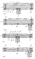
- Figures 1 and 2 show an example of a possible vertical cross section or a floor plan of the building constructed according to the invention.
- the main idea of the invention is both the eaves walls and the Gable walls consist of elongated, in principle, extending over the entire height of the building To erect sandwich panels in the area of their vertical Longitudinal sides in double T-profile beams that extend over the entire height of the building or in the area of the building corners are partially inserted in U-profile beams.
- an outer wall preferably has essentially the following structure with the thicknesses given, for example: ca values 3 - Silicone resin plaster (applied after the building is erected) 0.50 cm 4 - Plaster base plate 3.20 cm 5 - Air layer 4.00 cm 6 - Chipboard 0.40 cm 7 - Rigid foam layer, e.g. B. EPS rigid foam (expanded polysterol) 15.20 cm 8th - Chipboard 0.40 cm 9 - Air layer 4.00 cm 10 - Plasterboard 1.25 cm 28.95 cm
- an inner wall preferably has essentially the following structure, with the thickness dimensions given, for example: ca values 11 - Plasterboard 1.25 cm 12 - Air layer 4.00 cm 13 - Chipboard 0.40 cm 14 - EPS foam layer 5.90 cm 15 - Chipboard 0.40 cm 16 - Air layer 4.00 cm 17 - Plasterboard 1.25 cm 17.20 cm
- T-beams and U-beams offer the advantage that the Sandwich panels each securely between the opposite profile legs let insert, by the thickness of the thickness of these sandwich panels in each case adjacent, in particular thermally insulating air cushions or Air layers 5, 9 or 12, 16 is determined when on the outside of these profile legs e.g. B. plaster base plates 4 or plasterboard 10, 11, 16 or other Plate elements are attached.
- the actual sandwich panels 1 and 2 are each composed of particle board 6 or 13, EPS hard foam layer 7 or 14 and chipboard 8 or 15.
- the double-T profile supports 19 and sandwich panels 2 provided for interior walls have lengths matched to the individual storey height.
- each sandwich panel 1 and 2 is located in the finished building of its four edges, its conclusion in U-shaped beams, especially made of wood, whereby between adjacent sandwich panels 1 and 2, a double-T support profile geometrically speaking, two with the base webs lying against each other Has U-profile sections.
- the sandwich panels 1 and 2 are in accordance with the intended door and window openings already provided with appropriate cutouts in the factory, where, where necessary, appropriate lintels are attached.
- the thickness of the double-T flange corresponds to the thickness of the air layers 5, 9 or 12, 16.
- the double-T girders and sandwich panels forming the gable walls 7 extend over the entire building, ie from the floor panel a to the roof d .
- the outer wall panels 1 are at their lower and upper ends Provide air openings that open into the air layer 5, so that, as by the Arrows f1 and f2 indicated an air circulation caused by thermal buoyancy is guaranteed to improve the indoor climate.
- Figures 4 and 7 show the connection of a glued wood ceiling element 25 z. B. on the eaves wall b by means of preferably U-shaped rails 26 made of metal, which are preferably attached to the double-T beams 18 at ceiling height over the entire inner width of the outer walls b and c .
- U-shaped rails 26 instead of U-shaped rails 26 as a support for the ceiling elements 25, rectangular wooden support beams can also be provided, which are fastened to the supports 18.
- fastening anchors 40 are on the upper side of a ceiling element 25 attached, which preferably have a Z-profile.
- One leg 40.1 is in the Top of the ceiling element 25 inserted, while the web portion 40.3 in essentially flat or parallel to the ceiling element level on the ceiling element 25 is attached.
- the second leg 40.3 of the Z-profile is directed upwards and points an opening, not shown, for an anchoring screw 41, which is suitable Way is fixed in a double T-beam 18.
- Same fasteners 40/41 over the entire circumference are preferably made of several ceiling elements 25 composite floor ceiling and thus along the inside the outer walls are distributed overall.
- FIG. 5 shows a carrier profile in the area of a corner connection between two outer wall sandwich panels 1.
- the sandwich panel forming part of the eaves wall b is terminated in the area of a T-shaped beam 20, which is connected with the underside of its web 20.1 to a U-shaped beam 21 by gluing on the one hand and by means of a spring rail 22 on the other hand, which is in corresponding recesses in the T -Profile support 20 and in the U-profile support 21 is used.
- a rectangular bar 23 is attached to the outside of the inside leg of the U-beam profile 21 for fastening the inside plasterboard 10.
- the outward-facing flange 20.2 of the T-profile 20 has a width which essentially corresponds to the air layer 5 of the outer wall sandwich panel 1.
- the invention For a 45 ° connection of two outer wall sandwich panels 1, the invention essentially started from two double-T-beams 23, 24, which in Area of their mutually facing flanges are mitred so that the supporting timbers, which abut one another at an angle, are cut at an angle and bluntly glue together surfaces.
- the length of the facing each other Flanges 23.1 and 24.1 are based on the angular size of the respective connection point vote.
- the flanges as a whole on the mutually facing regions of the supports 23, 24.
- the space between the supports 23 and 24 is preferably with EPS foam filled.
- Figure 7 also shows a schematic representation of the junction between a eaves wall b and the roof d .
- the individual outer wall sandwich panels 1, including the double-T profile girders 18 of the eaves walls b that delimit them, are raised directly up to the roof girder beams 50 and support a support beam 51 which extends over the entire roof length and is inserted into the roof girder beams 50.
- FIG. 8 shows the floor and ceiling connections of an inner wall sandwich element 2 and thus an inner wall using U-profiles 27, 28 made of wood.
- Figures 9-12 show connection points of inner wall sandwich panels 2 and thus of inner walls on the one hand on outer wall sandwich panels 1 and on the other hand on inner wall sandwich panels 2 by means of U-profiles, each of the end profiles of the respective Form interior wall sandwich panels.
- each outer wall sandwich panel 1 On the inner wall surfaces of each outer wall sandwich panel 1 are between the Chipboard 8 and the plasterboard 10 spacer and stiffening strips 29 attached, that run parallel to the double-T beams. Comparable distance and Stiffening strips 30 can also between the chipboard 13 and 15 and the Plasterboard 11 or 17 may be provided.
- the U-profiles are either against the chipboard 8 or 15 or against the double-T profile carrier 18 or 19 and possibly additional stiffening and spacer strips 31 and 32 respectively.
- outer walls composed of several outer wall sandwich panels 1 can at least largely be completed at the factory or only at the construction site are put together, with respect to size, i.e. H. Height and width each factory-assembled outer wall, mainly limited by Transport conditions from the factory to the construction site are available.
- a floor slab or cellar ceiling a is provided by the customer.
- the construction of the building then takes place essentially from the inside by placing the first eaves wall b and the inner walls of the ground floor on the base plate a and placing ceiling elements 25 extending over the entire inner surface of the building on these inner walls and inserting them into the U-shaped rail 26 .
- Inner walls of the first upper floor are in turn placed on these lower ceiling elements 25, and further ceiling elements 25 are placed on these inner walls and pushed into the next U-shaped rail.
- the second prefabricated eaves wall b is then attached, the individual ceiling elements 25 being inserted into U-profiles 26 fastened to the eaves walls according to FIG. 7.
- the U-beam 21 is fastened to the T-beam 20 forming the end of the eaves wall b in the manner described in FIG.
- a first outer wall sandwich panel 1 is then inserted into the U-profile carrier 21 from the side, to the free longitudinal edge of which a double-T profile carrier 18 is already attached, into the free profile side of which a further sandwich panel can be inserted and so on.
- a U-profile support 21 is fastened to the second eaves wall b , so that finally a last sandwich panel can be inserted from above.
- the length of the individual sandwich panels can be divided depending on the height of the building, so that they then lie against one another with their horizontally running end faces and can optionally be connected to one another.
- a gable wall c with the exception of the outer sandwich panels separately from the building skeleton and then fastening it as a unit to the floor ceilings or ceiling elements.
- the two outer outer wall sandwich panels 1 of the gable wall c are then inserted from above into the open profile spaces, on the one hand, of the final double-T profile beams 18 or the two outer U-profile beams 20.
- the anchoring screws 41 can either be factory or only on site be attached to the double-T profile beams.
- the attachment anchors 40 are preferred only attached to the ceiling elements 25 when the building was erected, by the legs 40.2 pushed onto the anchoring screws 41 and with her leg 40.1 used in prefabricated grooves on the top of the ceiling elements become.
- the web section 40.3 of the individual fastening anchor can then be screwed in place on the top of the ceiling element 25 before the If necessary, nut 42 is screwed on and tightened beforehand.
- the individual floor ceiling is preferably divided into a plurality of ceiling elements 25, the length of which corresponds to the distance between opposing outer walls of the building, preferably the distance between the two gable walls c .
Landscapes
- Engineering & Computer Science (AREA)
- Architecture (AREA)
- Physics & Mathematics (AREA)
- Electromagnetism (AREA)
- Civil Engineering (AREA)
- Structural Engineering (AREA)
- Load-Bearing And Curtain Walls (AREA)
- Joining Of Building Structures In Genera (AREA)
Abstract
Description
Die Figuren 1 und 2 zeigen in beispielhafter Weise einen mögichen vertikalen Querschnitt bzw. einen Grundriß des erfindungsgemäß errichteten Gebäudes.
| ca-Werte | ||
| 3 - | Silikonharzputz (nach Errichtung des Gebäudes aufgetragen) | 0,50 cm |
| 4 - | Putzträgerplatte | 3,20 cm |
| 5 - | Luftschicht | 4,00 cm |
| 6 - | Spanplatte | 0,40 cm |
| 7 - | Hartschaumschicht, z. B. EPS-Hartschaum (expandiertes Polysterol) | 15,20 cm |
| 8 - | Spanplatte | 0,40 cm |
| 9 - | Luftschicht | 4,00 cm |
| 10 - | Gipskartonplatte | 1,25 cm |
| |
| ca-Werte | ||
| 11 - | Gipskartonplatte | 1,25 cm |
| 12 - | Luftschicht | 4,00 cm |
| 13 - | Spanplatte | 0,40 cm |
| 14 - | EPS-Hartschaumschicht | 5,90 cm |
| 15 - | Spanplatte | 0,40 cm |
| 16 - | Luftschicht | 4,00 cm |
| 17 - | Gipskartonplatte | 1,25 cm |
| |
Figur 5 zeigt ein Trägerprofil im Bereich einer Eckverbindung zwischen zwei Außenwand-Sandwichplatten 1.
Der nach außen gerichtete Flansch 20.2 des T-Profils 20 hat zur Bildung einer Luftschicht 5' eine Breite, die im wesentlichen der Luftschicht 5 der Außenwand-Sandwichplatte 1 entspricht.
Claims (14)
- Gebäude, insbesondere für Wohn- oder Bürozwecke, das aus fabrikmäßig vorgefertigten Bauelementen in Form von Sandwichplatten und die Sandwichplatten einfassenden Profilträgern errichtet ist, ist dadurch gekennzeichnet, daß die Profilträger der Gebäudeaußenwände aus Holz bestehen und sich durchlaufend über die gesamte Gebäudehöhe erstrecken und in Form von Doppel-T- und U-Profilen ausgebildet sind, und daß die Geschoßdecken in Form von langgestreckten Deckenelementen (25) sich zwischen zwei gegenüberliegenden Außenwänden erstrecken und an den Profilträgern gelagert und mit diesen verspannt sind.
- Gebäude nach Anspruch 1, dadurch gekennzeichnet, daß die Profilträger zwischen zwei in einer Ebene liegenden, benachbarten Sandwichplatten 1 als Doppel-T-Profilträger (18) ausgebildet sind, und daß bei zwei sich gegenüberliegenden Außenwänden die im Bereich der Gebäudeecken befindlichen Sandwichplatten in vertikaler Richtung durch U-Profilträger begrenzt sind.
- Gebäude nach Anspruch 1, dadurch gekennzeichnet, daß die unteren und oberen Ränder der sich über die Gebäudehöhe erstreckenden Sandwichplatten durch U-Profilträger begrenzt sind.
- Gebäude nach Anspruch 1, dadurch gekennzeichnet, daß zur Abstützung der Dekkenelemente (25) an den Profilträgern (18) horizontal verlaufende Balken, insbesondere U-Profilschienen (26) aus Metall, befestigt sind.
- Gebäude nach Anspruch 1, dadurch gekennzeichnet, daß zum Verspannen der Deckenelemente (25) mit den Profilträgern (18) Verspanneinrichtungen vorgesehen sind, mit denen der einzelne Profilträger (18) gegen das Deckenelement gezogen ist.
- Gebäude nach Anspruch 5, dadurch gekennzeichnet, daß die Verspanneinrichtung eine in dem Profilträger (18) verankerte Verankerungsschraube (41) und einen an dem Deckenelement (25) befestigten Befestigungsanker (40) in Form eines Z-Profils umfaßt, dessen erster Schenkel (40.1) in das Deckenelement eingesetzt ist, dessen Steg (40.3) flächig an dem Deckenelement befestigt ist, und dessen zweiter Schenkel (40.2) eine Öffnung zum Durchstecken der Verankerungsschraube (41) aufweist, auf die eine Befestigungsmutter (42) aufgeschraubt ist.
- Gebäude nach Anspruch 1, welches ein Satteldach aufweist, dadurch gekennzeichnet, daß im Bereich der Traufwände (b) die Profilträger und die Sandwichplatten bis zur Unterkante der schräg verlaufenden Dachträger (50) durchgezogen und entsprechend der Dachneigung auf Gehrung geschnitten sind und gegen eine an dem Dachbalken (50) angebrachte, in Dachlängsrichtung verlaufende Stützplatte (51) anliegen.
- Gebäude nach Anspruch 7, dadurch gekennzeichnet, daß die einen Teil der Traufwand (b) bildende Sandwichplatte ihren Abschluß im Bereich eines Profilträgers (20) findet, der mit der Unterseite seines Steges (20.1) an einen U-Profilträger (21) durch Verleimung einerseits und mittels einer Federschiene (22) andererseits angeschlossen ist, die in entsprechende Ausnehmungen im T-Profilträger (20) und im U-Profilträger (21) eingesetzt ist, und daß an die Außenseite des innen liegenden Schenkels des U-Trägerprofils (21) ein rechtecker Balken (23) zur Befestigung einer innen liegenden Gipskartonplatte (10) angefügt ist.
- Gebäude nach Anspruch 1, dadurch gekennzeichnet, daß die Profilträger und die Sandwichplatten mit fabrikmäßig angebrachten Tür- und Fensteröffnungen und entsprechenden Stürzen versehen sind.
- Gebäude nach Anspruch 1, dadurch gekennzeichnet, daß die Außenwände im wesentlichen folgenden bevorzugten Aufbau haben:
ca-Werte 3 - Silikonharzputz (nach Errichtung des Gebäudes aufgetragen) 0,50 cm 4 - Putzträgerplatte (nach Errichtung des Gebäudes aufgetragen) 3,20 cm 5 - Luftschicht 4,00 cm 6 - Spanplatte 0,40 cm 7 - Hartschaumschicht, z. B. EPS-Hartschaum (expandiertes Polysterol) 15,20 cm 8 - Spanplatte 0,40 cm 9 - Luftschicht 4,00 cm 10 - innere Gipskartonplatte 1,25 cm 28,95 cm - Gebäude nach Anspruch 10, gekennzeichnet durch Entlüftungsöffnungen, die im Bereich der unteren und oberen Wandabschnitte jeder Außenwand zwischen benachbarten Profilträgern (18, 20, 21) durch die Silikonharzputzschicht (3) und die äußere Putzträgerplatte (4) in die Luftschicht (5) münden.
- Verfahren zum Errichten eines Gebäudes, insbesondere für Wohn- und Bürozwecke aus
fabrikmäßig vorgefertigten Bauelementen, insbesondere in Form von Sandwichplatten und die Sandwichplatten einfassenden Profilträgern für die Außen- und Innenwände sowie
vorgefertigten Deckenelementen für die Geschoßdecken, gekennzeichnet durch folgende Schritte:a) für die Außenwände werden sich über die gesamte Gebäudehöhe erstreckende Profilträger und Sandwichplatten angefertigt;b) zwei sich gegenüberliegende Außenwände (b) werden fabrikseitig oder bauseitig in Teilabschnitten oder insgesamt zusammengesetzt;c) eine Außenwand (b) wird mit vorgefertigten Innenwänden auf einer bauseitig vorhandenen Bodenseite (a) in der endgültigen Gebäudekonfiguration abgestellt;d) ein erstes sich über die gesamte Länge der aufgerichteten Außenwand erstreckendes Deckenelement (25) wird auf die Innenwandelemente aufgelegt und an einem an der bereits errichteten Außenwand befindlichen, horizontal verlaufenden Balken, vorzugsweise einer U-Profilschiene (26) aus Metall, abgestützt und mittels Verankerungseinrichtungen an den vertikal verlaufenden Profilträgern der Außenwand (b) verankert und verspannt;e) es werden weitere Deckenelemente (25) bis in den Bereich der zweiten Au Außenwand (b) auf die Innenwände aufgelegt;f) die zweite Außenwand (b) wird insgesamt oder in Teilabschnitten gegen das bereits errichtete Gebäudeskelett angelegt, wobei eine an dieser zweiten Außenwand (b) befindliche U-Profilschiene (26) aus Metall über den freiliegenden Rand des zuletzt aufgelegten Deckenelementes (25) geschoben wird und diese zweite Außenwand mittels an ihren Profilträgern befestigten Verankerungseinrichtungen an diesem Deckenelement befestigt und damit verspannt wird;g) die beiden weiteren zu den bereits errichteten Außenwänden (b) senkrecht stehenden Außenwände (c) werden in Teilabschnitten zwischen die bereits aufgerichteten Außenwände (b) eingefügt, wobei an diesen Außenwand-Teilabschnitten angebrachte U-Profilschienenabschnitte über die Deckenelemente geschoben und an diesen Deckenelementen mittels Verankerungseinrichtungen verankert und verspannt werden. - Verfahren nach Anspruch 12, gekennzeichnet durch folgende Schritte beim Errichten der Außenwände (c) gemäß Schritt (g):h) an den sich jeweils gegenüberliegenden Enden der Außenwände (b) werden nach innen offene U-Profilträger (21) angebracht;i) eine erste Außenwand-Sandwichplatte (1), die mit ihrem einen Rand in einen Doppel-T-Profilträger (18) eingefügt ist, wird mit ihrem freien Rand in einen der an der Außenwand (b) angebrachten U-Profilträger (21) eingefügt und an einem Deckenelement (25) verankert;j) es wird eine zweite Außenwand-Sandwichplatte (1) in der gemäß Schritt (h) beschriebenen Weise an den bereits errichteten Wandabschnitt angesetzt und so fort;k) die letzte Außenwand-Sandwichplatte (1) wird von oben her in die einander zugewandten U-Profil-Hohlräume der vorhandenen U-Profile eingeschoben und an den gegenüberliegenden Deckenelementen (25) befestigt bzw. verankert.
- Verfahren nach Anspruch 12, dadurch gekennzeichnet, daß man an den sich jeweils gegenüberliegenden Enden der Außenwände (b) nach innen hin offene U-Profilträger (21) anbringt,daß man die Außenwand (c) mit Ausnahme der beiden äußeren Außenwand-Sandwichplatten (1) zusammenfügt und als Einheit gegen das bereits errichtete Gebäudeskelett anstellt und an den Deckenwandelementen (25) befestigt und verankert,und daß man abschließend von oben her die beiden äußeren Sandwichplatten-Elemente in die sich gegenüberliegenden Hohlräume der vorhandenen U-Profile einschiebt und mit den Deckenelementen verankert.
Applications Claiming Priority (2)
| Application Number | Priority Date | Filing Date | Title |
|---|---|---|---|
| DE2000112483 DE10012483A1 (de) | 2000-03-15 | 2000-03-15 | Gebäude aus fabrikmäßig vorgefertigten Bauelementen und Verfahren zur Errichtung desselben |
| DE10012483 | 2000-03-15 |
Publications (2)
| Publication Number | Publication Date |
|---|---|
| EP1134324A2 true EP1134324A2 (de) | 2001-09-19 |
| EP1134324A3 EP1134324A3 (de) | 2002-06-12 |
Family
ID=7634733
Family Applications (1)
| Application Number | Title | Priority Date | Filing Date |
|---|---|---|---|
| EP01105972A Withdrawn EP1134324A3 (de) | 2000-03-15 | 2001-03-10 | Gebäude aus fabrikmässig vorgefertigten Bauelementen sowie Verfahren zur Errichtung eines solchen Gebäudes |
Country Status (2)
| Country | Link |
|---|---|
| EP (1) | EP1134324A3 (de) |
| DE (1) | DE10012483A1 (de) |
Citations (1)
| Publication number | Priority date | Publication date | Assignee | Title |
|---|---|---|---|---|
| DE3311564C2 (de) | 1983-03-30 | 1986-05-22 | Reinhold 7410 Reutlingen Gorzellik | Haus-Bausystem mit Holzskelettkonstruktion und vorgefertigten Außenwand-Elementen |
Family Cites Families (10)
| Publication number | Priority date | Publication date | Assignee | Title |
|---|---|---|---|---|
| DE817517C (de) * | 1948-10-31 | 1951-10-18 | Erwin Huber | Verfahren zum Aufstellen eines Fachwerkgeruestes fuer mindestens zweigeschossige Haeuser |
| US3082848A (en) * | 1958-12-03 | 1963-03-26 | Robert R Keller | Multiple-panel load-bearing building walls and load-bearing panel units therefor |
| DE2604704A1 (de) * | 1976-02-06 | 1977-08-11 | Wolfgang Hippmann | Fassadenplatte mit witterungsbestaendiger oberflaechenschicht und verfahren zu ihrer herstellung |
| DE2619020A1 (de) * | 1976-04-30 | 1977-11-10 | Suellhoefer Heinz | Sandwich-element |
| DE2807045A1 (de) * | 1978-02-18 | 1979-08-23 | Messerschmitt Boelkow Blohm | Versetzbare trennwand |
| DE3244406A1 (de) * | 1981-12-04 | 1984-05-03 | Ernst Ing. 1130 Wien Perner | Fertigteilhaussystem |
| NL8201299A (nl) * | 1982-03-29 | 1983-10-17 | Staalframe Bv | Gebouw, wandsecties en profielen daarvoor. |
| DE8309825U1 (de) * | 1983-04-02 | 1983-11-24 | Paul Solbach Gmbh & Co Kg, 5222 Morsbach | Aus doppelwandigen platten gebildete raumzelle |
| DE9415489U1 (de) * | 1994-09-24 | 1995-07-27 | Bernhardt, geb. Wabnik, Gerrit, 35444 Biebertal | Haltespange zur Venenkatheter-Entlastung bei Infusionen |
| DE19708868C2 (de) * | 1997-03-05 | 1999-07-01 | Heinemann Herbert | Vorgefertigtes Verkleidungselement zum Verkleiden von Gebäudewänden |
-
2000
- 2000-03-15 DE DE2000112483 patent/DE10012483A1/de not_active Withdrawn
-
2001
- 2001-03-10 EP EP01105972A patent/EP1134324A3/de not_active Withdrawn
Patent Citations (1)
| Publication number | Priority date | Publication date | Assignee | Title |
|---|---|---|---|---|
| DE3311564C2 (de) | 1983-03-30 | 1986-05-22 | Reinhold 7410 Reutlingen Gorzellik | Haus-Bausystem mit Holzskelettkonstruktion und vorgefertigten Außenwand-Elementen |
Also Published As
| Publication number | Publication date |
|---|---|
| DE10012483A1 (de) | 2001-09-27 |
| EP1134324A3 (de) | 2002-06-12 |
Similar Documents
| Publication | Publication Date | Title |
|---|---|---|
| DE3430612A1 (de) | Metall-raumfachwerk aus einzelelementen zum errichten von gebaeuden | |
| DE3408390A1 (de) | Raumzelle | |
| DE8008815U1 (de) | Stuetze zur erstellung von gebaeuden | |
| DE60033392T2 (de) | Gebäudekonstruktion | |
| EP0051319B1 (de) | Hohlprofil-Stütz- und/oder -Montageelement für in Elementbauweise zu erstellende Gebäude | |
| DE7027429U (de) | Vorgefertigtes raumelement zur errichtung von gebaeuden. | |
| EP1134324A2 (de) | Gebäude aus fabrikmässig vorgefertigten Bauelementen sowie Verfahren zur Errichtung eines solchen Gebäudes | |
| DE3532846A1 (de) | Bauelement zur erstellung von gebaeuden, auch zur erstellung von gebaeudemodellen | |
| DE3889056T2 (de) | Verfahren zur Errichtung eines Modulargebäudes. | |
| DE20007290U1 (de) | Gebäude aus fabrikmäßig vorgefertigten Bauelementen | |
| DE29612763U1 (de) | Holzhaus und zu dessen Herstellung bestimmte Wandtafel | |
| DE4211435A1 (de) | Integrationsbauverfahren und Baustein für seine Durchführung | |
| DE19521990C2 (de) | Raumzellen-Modul | |
| AT304020B (de) | Gebaeudekonstruktion | |
| DE29805998U1 (de) | Einziehwand und Bausatz bzw. Bauelement zum Bau der Einziehwand | |
| DE4211929A1 (de) | Fertighaus | |
| DE2540915A1 (de) | Aussenwandkonstruktion fuer bauwerke | |
| DE2630120A1 (de) | Gebaeude, insbesondere fertighaus | |
| DE3117182A1 (de) | Bausystem fuer insbesondere mehrgeschossige gebaeude | |
| DE9208102U1 (de) | Bausatz zum Erstellen eines Gebäudes o.dgl. Bauwerkes | |
| DE102015118975A1 (de) | Bausatz aus Bauelementen zum Herstellen eines Gebäudes und Verfahren zum Herstellen eines Gebäudes | |
| DE19714792A1 (de) | Fertighaus und vorgefertigtes Element hierfür | |
| DE1609361C3 (de) | Gebäude mit vorgefertigten, geschlossenen, einzelligen Rahmenelementen aus Stahlbeton | |
| EP3067483B1 (de) | Wandaufbau für ein Gebäudesystem, insbesondere Wohngebäude | |
| DE3309645A1 (de) | Bautafel aus holz sowie gebaeude aus vorgefertigten holzbauteilen |
Legal Events
| Date | Code | Title | Description |
|---|---|---|---|
| PUAI | Public reference made under article 153(3) epc to a published international application that has entered the european phase |
Free format text: ORIGINAL CODE: 0009012 |
|
| AK | Designated contracting states |
Kind code of ref document: A2 Designated state(s): AT BE CH CY DE DK ES FI FR GB GR IE IT LI LU MC NL PT SE TR |
|
| AX | Request for extension of the european patent |
Free format text: AL;LT;LV;MK;RO;SI |
|
| PUAL | Search report despatched |
Free format text: ORIGINAL CODE: 0009013 |
|
| 17P | Request for examination filed |
Effective date: 20020318 |
|
| AK | Designated contracting states |
Kind code of ref document: A3 Designated state(s): AT BE CH CY DE DK ES FI FR GB GR IE IT LI LU MC NL PT SE TR |
|
| AX | Request for extension of the european patent |
Free format text: AL;LT;LV;MK;RO;SI |
|
| RIC1 | Information provided on ipc code assigned before grant |
Free format text: 7E 04B 1/14 A, 7E 04B 1/26 B |
|
| AKX | Designation fees paid |
Designated state(s): AT BE CH CY DE DK ES FI FR GB GR IE IT LI LU MC NL PT SE TR |
|
| 17Q | First examination report despatched |
Effective date: 20031112 |
|
| STAA | Information on the status of an ep patent application or granted ep patent |
Free format text: STATUS: THE APPLICATION IS DEEMED TO BE WITHDRAWN |
|
| 18D | Application deemed to be withdrawn |
Effective date: 20041001 |