EP1134417B1 - Pompe à déplacement positif - Google Patents
Pompe à déplacement positif Download PDFInfo
- Publication number
- EP1134417B1 EP1134417B1 EP01104428A EP01104428A EP1134417B1 EP 1134417 B1 EP1134417 B1 EP 1134417B1 EP 01104428 A EP01104428 A EP 01104428A EP 01104428 A EP01104428 A EP 01104428A EP 1134417 B1 EP1134417 B1 EP 1134417B1
- Authority
- EP
- European Patent Office
- Prior art keywords
- vane
- displacement pump
- positive
- housing interior
- drive shaft
- Prior art date
- Legal status (The legal status is an assumption and is not a legal conclusion. Google has not performed a legal analysis and makes no representation as to the accuracy of the status listed.)
- Expired - Lifetime
Links
- 238000006073 displacement reaction Methods 0.000 title claims abstract description 19
- 238000007789 sealing Methods 0.000 claims description 24
- 230000006835 compression Effects 0.000 claims description 3
- 238000007906 compression Methods 0.000 claims description 3
- 239000000919 ceramic Substances 0.000 abstract description 5
- 239000004033 plastic Substances 0.000 abstract description 4
- 239000002184 metal Substances 0.000 abstract description 2
- 239000002131 composite material Substances 0.000 abstract 1
- 230000002093 peripheral effect Effects 0.000 description 4
- 239000004696 Poly ether ether ketone Substances 0.000 description 2
- 239000004734 Polyphenylene sulfide Substances 0.000 description 2
- 229920010524 Syndiotactic polystyrene Polymers 0.000 description 2
- 238000010276 construction Methods 0.000 description 2
- 229920002530 polyetherether ketone Polymers 0.000 description 2
- 229920000069 polyphenylene sulfide Polymers 0.000 description 2
- 239000004721 Polyphenylene oxide Substances 0.000 description 1
- UCKMPCXJQFINFW-UHFFFAOYSA-N Sulphide Chemical compound [S-2] UCKMPCXJQFINFW-UHFFFAOYSA-N 0.000 description 1
- 230000006978 adaptation Effects 0.000 description 1
- 238000005516 engineering process Methods 0.000 description 1
- 239000012530 fluid Substances 0.000 description 1
- 230000003993 interaction Effects 0.000 description 1
- 239000007788 liquid Substances 0.000 description 1
- 238000004519 manufacturing process Methods 0.000 description 1
- 229920000570 polyether Polymers 0.000 description 1
- 238000005086 pumping Methods 0.000 description 1
Images

Classifications
-
- F—MECHANICAL ENGINEERING; LIGHTING; HEATING; WEAPONS; BLASTING
- F04—POSITIVE - DISPLACEMENT MACHINES FOR LIQUIDS; PUMPS FOR LIQUIDS OR ELASTIC FLUIDS
- F04C—ROTARY-PISTON, OR OSCILLATING-PISTON, POSITIVE-DISPLACEMENT MACHINES FOR LIQUIDS; ROTARY-PISTON, OR OSCILLATING-PISTON, POSITIVE-DISPLACEMENT PUMPS
- F04C2/00—Rotary-piston machines or pumps
- F04C2/30—Rotary-piston machines or pumps having the characteristics covered by two or more groups F04C2/02, F04C2/08, F04C2/22, F04C2/24 or having the characteristics covered by one of these groups together with some other type of movement between co-operating members
- F04C2/34—Rotary-piston machines or pumps having the characteristics covered by two or more groups F04C2/02, F04C2/08, F04C2/22, F04C2/24 or having the characteristics covered by one of these groups together with some other type of movement between co-operating members having the movement defined in groups F04C2/08 or F04C2/22 and relative reciprocation between the co-operating members
- F04C2/344—Rotary-piston machines or pumps having the characteristics covered by two or more groups F04C2/02, F04C2/08, F04C2/22, F04C2/24 or having the characteristics covered by one of these groups together with some other type of movement between co-operating members having the movement defined in groups F04C2/08 or F04C2/22 and relative reciprocation between the co-operating members with vanes reciprocating with respect to the inner member
- F04C2/3441—Rotary-piston machines or pumps having the characteristics covered by two or more groups F04C2/02, F04C2/08, F04C2/22, F04C2/24 or having the characteristics covered by one of these groups together with some other type of movement between co-operating members having the movement defined in groups F04C2/08 or F04C2/22 and relative reciprocation between the co-operating members with vanes reciprocating with respect to the inner member the inner and outer member being in contact along one line or continuous surface substantially parallel to the axis of rotation
-
- F—MECHANICAL ENGINEERING; LIGHTING; HEATING; WEAPONS; BLASTING
- F01—MACHINES OR ENGINES IN GENERAL; ENGINE PLANTS IN GENERAL; STEAM ENGINES
- F01C—ROTARY-PISTON OR OSCILLATING-PISTON MACHINES OR ENGINES
- F01C21/00—Component parts, details or accessories not provided for in groups F01C1/00 - F01C20/00
- F01C21/08—Rotary pistons
- F01C21/0809—Construction of vanes or vane holders
- F01C21/0881—Construction of vanes or vane holders the vanes consisting of two or more parts
-
- F—MECHANICAL ENGINEERING; LIGHTING; HEATING; WEAPONS; BLASTING
- F04—POSITIVE - DISPLACEMENT MACHINES FOR LIQUIDS; PUMPS FOR LIQUIDS OR ELASTIC FLUIDS
- F04C—ROTARY-PISTON, OR OSCILLATING-PISTON, POSITIVE-DISPLACEMENT MACHINES FOR LIQUIDS; ROTARY-PISTON, OR OSCILLATING-PISTON, POSITIVE-DISPLACEMENT PUMPS
- F04C18/00—Rotary-piston pumps specially adapted for elastic fluids
- F04C18/30—Rotary-piston pumps specially adapted for elastic fluids having the characteristics covered by two or more of groups F04C18/02, F04C18/08, F04C18/22, F04C18/24, F04C18/48, or having the characteristics covered by one of these groups together with some other type of movement between co-operating members
- F04C18/34—Rotary-piston pumps specially adapted for elastic fluids having the characteristics covered by two or more of groups F04C18/02, F04C18/08, F04C18/22, F04C18/24, F04C18/48, or having the characteristics covered by one of these groups together with some other type of movement between co-operating members having the movement defined in group F04C18/08 or F04C18/22 and relative reciprocation between the co-operating members
- F04C18/344—Rotary-piston pumps specially adapted for elastic fluids having the characteristics covered by two or more of groups F04C18/02, F04C18/08, F04C18/22, F04C18/24, F04C18/48, or having the characteristics covered by one of these groups together with some other type of movement between co-operating members having the movement defined in group F04C18/08 or F04C18/22 and relative reciprocation between the co-operating members with vanes reciprocating with respect to the inner member
- F04C18/3441—Rotary-piston pumps specially adapted for elastic fluids having the characteristics covered by two or more of groups F04C18/02, F04C18/08, F04C18/22, F04C18/24, F04C18/48, or having the characteristics covered by one of these groups together with some other type of movement between co-operating members having the movement defined in group F04C18/08 or F04C18/22 and relative reciprocation between the co-operating members with vanes reciprocating with respect to the inner member the inner and outer member being in contact along one line or continuous surface substantially parallel to the axis of rotation
- F04C18/3442—Rotary-piston pumps specially adapted for elastic fluids having the characteristics covered by two or more of groups F04C18/02, F04C18/08, F04C18/22, F04C18/24, F04C18/48, or having the characteristics covered by one of these groups together with some other type of movement between co-operating members having the movement defined in group F04C18/08 or F04C18/22 and relative reciprocation between the co-operating members with vanes reciprocating with respect to the inner member the inner and outer member being in contact along one line or continuous surface substantially parallel to the axis of rotation the surfaces of the inner and outer member, forming the inlet and outlet opening
-
- F—MECHANICAL ENGINEERING; LIGHTING; HEATING; WEAPONS; BLASTING
- F04—POSITIVE - DISPLACEMENT MACHINES FOR LIQUIDS; PUMPS FOR LIQUIDS OR ELASTIC FLUIDS
- F04C—ROTARY-PISTON, OR OSCILLATING-PISTON, POSITIVE-DISPLACEMENT MACHINES FOR LIQUIDS; ROTARY-PISTON, OR OSCILLATING-PISTON, POSITIVE-DISPLACEMENT PUMPS
- F04C2/00—Rotary-piston machines or pumps
- F04C2/30—Rotary-piston machines or pumps having the characteristics covered by two or more groups F04C2/02, F04C2/08, F04C2/22, F04C2/24 or having the characteristics covered by one of these groups together with some other type of movement between co-operating members
- F04C2/34—Rotary-piston machines or pumps having the characteristics covered by two or more groups F04C2/02, F04C2/08, F04C2/22, F04C2/24 or having the characteristics covered by one of these groups together with some other type of movement between co-operating members having the movement defined in groups F04C2/08 or F04C2/22 and relative reciprocation between the co-operating members
- F04C2/344—Rotary-piston machines or pumps having the characteristics covered by two or more groups F04C2/02, F04C2/08, F04C2/22, F04C2/24 or having the characteristics covered by one of these groups together with some other type of movement between co-operating members having the movement defined in groups F04C2/08 or F04C2/22 and relative reciprocation between the co-operating members with vanes reciprocating with respect to the inner member
- F04C2/3441—Rotary-piston machines or pumps having the characteristics covered by two or more groups F04C2/02, F04C2/08, F04C2/22, F04C2/24 or having the characteristics covered by one of these groups together with some other type of movement between co-operating members having the movement defined in groups F04C2/08 or F04C2/22 and relative reciprocation between the co-operating members with vanes reciprocating with respect to the inner member the inner and outer member being in contact along one line or continuous surface substantially parallel to the axis of rotation
- F04C2/3442—Rotary-piston machines or pumps having the characteristics covered by two or more groups F04C2/02, F04C2/08, F04C2/22, F04C2/24 or having the characteristics covered by one of these groups together with some other type of movement between co-operating members having the movement defined in groups F04C2/08 or F04C2/22 and relative reciprocation between the co-operating members with vanes reciprocating with respect to the inner member the inner and outer member being in contact along one line or continuous surface substantially parallel to the axis of rotation the surfaces of the inner and outer member, forming the working space, being surfaces of revolution
Definitions
- the invention relates to a positive displacement pump with a wing to separate the two chambers in the housing space of the pump housing, with the features of the preamble of Claim 1.
- Fig. 2A already shows a positive displacement pump known, the two chambers of the pump housing space separating, positively guided wing both ends one in the longitudinal direction of the wing movably guided and on the inner peripheral wall of the Carrying sealing strip adjacent to the housing.
- these are in Cross-section T-shaped, the T-bar on the outside is convex in cross section and accordingly the Only touches the peripheral wall along a surface line.
- the middle ledge is with one in the wing Longitudinal groove formed on the face in the longitudinal direction of the wing brought into engagement so that the sealing strips when the drive shaft rotates under the action of centrifugal force automatically on the inner wall of the housing invest.
- Positive displacement pumps of this embodiment are therefore suitable e.g. not for the evacuation of a brake booster a motor vehicle, since in this case even small ones Speeds an evacuation must be ensured.
- a positive displacement pump is known from US-A-1,972,864, in which the wing is divided into two and the two wing parts pushed apart by a spring arranged between them so that they are on the inner peripheral surface issue.
- a vane pump known, which also has a divided wing, the facing ends of the wing parts teeth and have tooth gaps over which they interlock to grab.
- the two are Wing parts do not end at their facing each other sufficient against attacking on the wing tips Supported tangential forces.
- the object underlying the invention now exists in specifying a positive displacement pump in which the Wing parts against forces acting on the wing tips are better supported.
- the wing construction according to the invention makes it unnecessary a sliding arrangement of sealing strips on the Wing ends in the longitudinal direction of the wing, which e.g. in the DE-A-41 07 720 is disclosed.
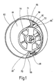
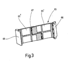
- a displacement pump according to Figures 1 and 2 comprises a flange body with a pump housing 61 forming cylinder pot 62, one stored in this Pump drive shaft 63 with attached rotor 64 and one in a recess running across the center of the rotor guided, divided as a whole with 65, divided into two Wing. As shown in FIG. 3, this is preferably through symmetrical, flat wing sections 65 ', 65' 'formed, which each have a pivot bearing at their outer end, on which a sealing strip 66 about an axis of rotation of the rotor parallel axis is pivotally mounted.
- the sealing strips 66 face the wall of the cylinder pot 62 provided with a concave radius 68 (Fig. 1). Consequently there are two lines of contact at 69 and 70, which in Interaction with the flat wing sections 65 ', 65 " to seal the chambers in front of and behind the wing 65 serve. Radii 71 are at the ends of the sealing strips 66 and 72 are provided, which ensures optimal resealing is achieved.
- the rotor 64 is towards the drive shaft 63 as a guide for slotted the wing 65 and plugged onto the shaft 63, inserted or molded.
- This change in length is due to the radial mobility of the Wing sections 65 ', 65' 'balanced.
- the adaptation to the variable length in the angle of rotation happens through that Pressing the sealing strips 66 and taking the Wing 65 through the drive shaft 63 through the shaped spring 67 or by a corresponding compression spring, which the Wing sections 65 ', 65' 'apart and with this connected sealing strips 66 to the Pressed on cylinder wall.
- Rotor blades 18; 65, wing sections 65 ', 65' ', Sealing strips 20, 22; 66 and rotor 18; 64 can advantageous both from metal, plastic, ceramic, metal-plastic connection, Metal-ceramic connection, metal-plastic-ceramic connection or plastic-ceramic connection getting produced.
- PEEK polyether ether ketone
- PES polyether sulfide
- SPS syndiotactic polystyrene
- PPS polyphenylene sulfide
Landscapes
- Engineering & Computer Science (AREA)
- Mechanical Engineering (AREA)
- General Engineering & Computer Science (AREA)
- Rotary Pumps (AREA)
- Details And Applications Of Rotary Liquid Pumps (AREA)
- Structures Of Non-Positive Displacement Pumps (AREA)
- Electrically Driven Valve-Operating Means (AREA)
Claims (8)
- Pompe à refoulement (65) à ailette pour la séparation mutuelle de deux chambres dans un volume de boítier (62), pouvant être actionnée par un arbre moteur (63) logé dans le boítier de pompe (61) et dirigé vers celui-ci de manière réglable radialement, dans un plan contenant son axe, et portant chaque fois à son extrémité un listel d'étanchement (66) qui étanchéifie en agissant conjointement à la paroi périphérique intérieure du volume de boítier (62), et où les listels d'étanchement (66), indépendamment l'un de l'autre, sont mobiles radialement à l'axe de l'arbre moteur (63), tandis que sur l'ailette (65), au moins un accumulateur d'énergie (67) est prévu, dont la tâche est de conserver constamment en contact étanche les deux listels d'étanchement (66) avec la paroi périphérique intérieure du volume de boítier (62), où l'ailette (65) est guidée dans la rainure d'un rotor (64), logé dans le volume de boítier (62), et actionnable par l'arbre moteur (63), laquelle rainure est symétriquement située dans un plan qui comprend l'axe du rotor et où l'ailette (65) est constituée de deux tronçons d'ailette (65', 65''), entre lesquels l'accumulateur d'énergie (67) est disposé, et les tronçons d'ailette (65', 65''), à leurs extrémités frontales qui sont de dos l'une par rapport à l'autre, agissant comme languette et rainure, sont en prise l'un avec l'autre, caractérisée en ce que la rainure se déploie dans le sens de l'arbre moteur (63).
- Pompe à refoulement selon la revendication 1, caractérisée en ce que les tronçons d'ailette (65', 65'') sont façonnés symétriquement.
- Pompe à refoulement selon la revendication 1 ou 2, caractérisée en ce que les tronçons d'ailette (65', 65'') présentent un profil plat.
- Pompe à refoulement selon l'une des revendications précédentes, caractérisée en ce que les tronçons d'ailette (65', 65'') sont échelonnés symétriquement à leurs extrémités frontales qui sont de dos l'une par rapport à l'autre et en ce que les extrémités frontales s'appuient chaque fois au montant d'un ressort (67) en forme de z, introduite entre elles.
- Pompe à refoulement selon l'une des revendications précédentes, caractérisée en ce qu'aux extrémités de l'ailette, lesquelles s'appuient à la surface périphérique intérieure du volume de boítier (62), des listels d'étanchement (66) sont logés de manière pivotante.
- Pompe à refoulement selon la revendication 5, caractérisée en ce que les listels d'étanchement (66), comportent un contact sur deux lignes (69, 70) avec la surface périphérique intérieure du volume de boítier (62), vu dans le sens de la périphérie.
- Pompe à refoulement selon la revendication 6, caractérisée en ce que le côté du listel d'étanchement (66) tourné vers la surface périphérique intérieure est arqué de manière concave dans le sens de la périphérie du volume du boítier (62).
- Pompe à refoulement selon l'une des revendications précédentes, caractérisée en ce que la surface périphérique intérieure cylindrique du volume de boítier (62) comporte une forme périphérique
Priority Applications (2)
| Application Number | Priority Date | Filing Date | Title |
|---|---|---|---|
| EP04004782A EP1424495A3 (fr) | 2000-03-15 | 2001-02-27 | Pompe à palettes |
| EP03008524A EP1327778A3 (fr) | 2000-03-15 | 2001-02-27 | Pompe à palettes |
Applications Claiming Priority (4)
| Application Number | Priority Date | Filing Date | Title |
|---|---|---|---|
| DE2000112406 DE10012406A1 (de) | 2000-03-15 | 2000-03-15 | Vakuumpumpe |
| DE10012406 | 2000-03-15 | ||
| DE20018958U | 2000-11-07 | ||
| DE20018958U DE20018958U1 (de) | 2000-11-07 | 2000-11-07 | Schieber zum gegenseitigen Trennen der beiden Kammern im Gehäuseraum einer Flügelzellenpumpe oder eines solchen Motors |
Related Child Applications (1)
| Application Number | Title | Priority Date | Filing Date |
|---|---|---|---|
| EP03008524.5 Division-Into | 2003-04-12 |
Publications (3)
| Publication Number | Publication Date |
|---|---|
| EP1134417A2 EP1134417A2 (fr) | 2001-09-19 |
| EP1134417A3 EP1134417A3 (fr) | 2002-09-11 |
| EP1134417B1 true EP1134417B1 (fr) | 2003-09-24 |
Family
ID=26004832
Family Applications (3)
| Application Number | Title | Priority Date | Filing Date |
|---|---|---|---|
| EP01104428A Expired - Lifetime EP1134417B1 (fr) | 2000-03-15 | 2001-02-27 | Pompe à déplacement positif |
| EP03008524A Withdrawn EP1327778A3 (fr) | 2000-03-15 | 2001-02-27 | Pompe à palettes |
| EP04004782A Withdrawn EP1424495A3 (fr) | 2000-03-15 | 2001-02-27 | Pompe à palettes |
Family Applications After (2)
| Application Number | Title | Priority Date | Filing Date |
|---|---|---|---|
| EP03008524A Withdrawn EP1327778A3 (fr) | 2000-03-15 | 2001-02-27 | Pompe à palettes |
| EP04004782A Withdrawn EP1424495A3 (fr) | 2000-03-15 | 2001-02-27 | Pompe à palettes |
Country Status (5)
| Country | Link |
|---|---|
| US (1) | US6604924B2 (fr) |
| EP (3) | EP1134417B1 (fr) |
| CN (1) | CN1162621C (fr) |
| AT (1) | ATE250722T1 (fr) |
| DE (1) | DE50100666D1 (fr) |
Cited By (2)
| Publication number | Priority date | Publication date | Assignee | Title |
|---|---|---|---|---|
| DE102004001840B3 (de) * | 2004-01-07 | 2005-05-25 | Joma-Hydromechanic Gmbh | Verdrängerpumpe |
| DE102006016243A1 (de) * | 2006-03-31 | 2007-10-04 | Joma-Hydromechanic Gmbh | Rotorpumpe und Flügel für eine Rotorpumpe |
Families Citing this family (28)
| Publication number | Priority date | Publication date | Assignee | Title |
|---|---|---|---|---|
| DE10046697A1 (de) * | 2000-09-21 | 2002-04-11 | Bosch Gmbh Robert | Flügel aus Kunststoff für eine Flügelzellen-Vakuumpumpe |
| DE50300812D1 (de) * | 2003-04-24 | 2005-08-25 | Joma Hydromechanic Gmbh | Flügelzellenpumpe |
| DE102004034926B3 (de) * | 2004-07-09 | 2005-12-29 | Joma-Hydromechanic Gmbh | Einflügelvakuumpumpe |
| DE102004034925B3 (de) * | 2004-07-09 | 2006-02-16 | Joma-Hydromechanic Gmbh | Einflügelvakuumpumpe |
| DE102004064029B4 (de) * | 2004-07-09 | 2008-04-10 | Joma-Hydromechanic Gmbh | Einflügelvakuumpumpe |
| DE102004034922B4 (de) * | 2004-07-09 | 2006-05-11 | Joma-Hydromechanic Gmbh | Einflügelvakuumpumpe |
| GB0419496D0 (en) * | 2004-09-02 | 2004-10-06 | Wabco Automotive Uk Ltd | Improvements relating to vacuum pumps |
| DE102004053521A1 (de) * | 2004-10-29 | 2006-05-11 | Joma-Hydromechanic Gmbh | Flügel für eine Rotorpumpe |
| DE102005015721B3 (de) * | 2005-03-31 | 2006-12-21 | Joma-Hydromechanic Gmbh | Vakuumpumpe |
| ITMI20050685A1 (it) * | 2005-04-18 | 2006-10-19 | O M P Officine Mazzocco Pagnon | Pompa a palette per un motore per autoveicoli e paletta per tale pompa |
| DE102005050001A1 (de) * | 2005-10-13 | 2007-04-19 | Joma-Hydromechanic Gmbh | Rotorpumpe |
| DE102005056270B3 (de) * | 2005-11-14 | 2007-03-01 | Joma-Hydromechanic Gmbh | Rotorpumpe |
| CN101122365B (zh) * | 2006-08-08 | 2012-07-04 | 刘矗汀 | 流体通道上的穿轴叶块旋转式膨胀或压缩机构 |
| DE102009035000B4 (de) * | 2009-07-27 | 2013-03-28 | Sergej Semakin | Flügelzellenmaschine |
| EP2299055B1 (fr) | 2009-09-14 | 2014-11-12 | Pierburg Pump Technology GmbH | Pompe à vide à ailettes pour automobile |
| GB2486007B (en) * | 2010-12-01 | 2017-05-10 | Itt Mfg Enterprises Inc | Sliding vane pump |
| CN103930678B (zh) * | 2012-01-11 | 2016-03-30 | 三菱电机株式会社 | 叶片型压缩机 |
| US20150010421A1 (en) * | 2012-03-01 | 2015-01-08 | Torad Engineering, Llc | Sealing Element for Rotary Compressor |
| DE102012210048A1 (de) * | 2012-06-14 | 2013-12-19 | Joma-Polytec Gmbh | Verdrängerpumpe |
| DE202013000976U1 (de) * | 2013-02-01 | 2014-05-08 | Saeta Gmbh & Co. Kg | Flügel für eine Flügelzellenvorrichtung sowie Flügelzellenvorrichtung |
| DE102013215561A1 (de) * | 2013-08-07 | 2015-03-05 | Behr Gmbh & Co. Kg | Rotor für einen Elektromotor, Elektromotor und Klimaanlage |
| CN104131976A (zh) * | 2014-08-18 | 2014-11-05 | 王喜来 | 一种旋转式空压机 |
| DE102015213098B4 (de) * | 2015-07-13 | 2017-05-04 | Joma-Polytec Gmbh | Flügel für eine Flügelzellenpumpe und Flügelzellenpumpe |
| CN105864034B (zh) * | 2016-06-06 | 2019-06-21 | 陈继业 | 单滑片回转式容积泵 |
| CN109826788A (zh) * | 2019-01-31 | 2019-05-31 | 刘江 | 一种新型气、液泵 |
| CN110374874B (zh) * | 2019-07-29 | 2024-11-01 | 黄石东贝压缩机有限公司 | 一种多重防泄漏弹片式滑块机构 |
| CN110541826A (zh) * | 2019-10-21 | 2019-12-06 | 太仓束捍机电科技有限公司 | 一种真空束焊机用真空泵 |
| CN117759651A (zh) * | 2024-01-08 | 2024-03-26 | 长春工业大学 | 一种离合器分离泵转接支架 |
Family Cites Families (37)
| Publication number | Priority date | Publication date | Assignee | Title |
|---|---|---|---|---|
| US620636A (en) * | 1899-03-07 | Rotary engine | ||
| US884747A (en) * | 1904-12-02 | 1908-04-14 | Creamery Package Mfg Co | Rotary pump. |
| US1078301A (en) * | 1910-01-12 | 1913-11-11 | Junius M Horner | Rotary engine. |
| DE329066C (de) * | 1912-09-18 | 1920-11-13 | Paul Schaefer | Abdichtung des Kolbens von Kraftmaschinen mit umlaufenden, in der Kolbentrommel verschiebbaren Kolben mittels Keilwirkung |
| US1528075A (en) * | 1921-08-11 | 1925-03-03 | Joseph R Richer | Rotary pump and the like |
| DE385561C (de) * | 1922-01-08 | 1923-11-26 | App Bauanstalt Axmann & Co G M | Kolbenentlastungsvorrichtung fuer Drehkolbenkraftmaschinen mit in geschlossenen Schlitzen der Trommel verschiebbaren Kolben |
| US1649256A (en) * | 1923-02-10 | 1927-11-15 | Rotary Machine & Engineering C | Rotary pump |
| GB222242A (en) * | 1923-07-09 | 1924-10-02 | William Rogan | Improvements in or relating to rotary pumps |
| FR590546A (fr) * | 1924-06-03 | 1925-06-18 | Pompe centrifuge utilisable, notamment, comme compresseur rotatif | |
| US1658524A (en) * | 1925-02-10 | 1928-02-07 | John W Gurley | Rotary pump |
| US1972864A (en) * | 1930-10-15 | 1934-09-11 | Bradshaw & Company | Rotary pump |
| US2103180A (en) * | 1933-06-15 | 1937-12-21 | Rice Mfg And Aerial Transp Cor | Rotary motor |
| US2436876A (en) * | 1943-07-29 | 1948-03-02 | Alfred L Stamsvik | Rotary sliding vane pump structure |
| GB605740A (en) * | 1946-12-20 | 1948-07-29 | Derek Eyre Kirkland | Improvements in or relating to sliding-vane rotary pumps |
| US2631546A (en) * | 1948-10-19 | 1953-03-17 | Edward A Dawson | Rotary sliding vane pump |
| CH381797A (de) * | 1959-03-10 | 1964-09-15 | Kron Werner | Drehkolbenmaschine |
| FR1315068A (fr) * | 1961-11-09 | 1963-01-18 | Moteur à combustion interne à piston rotatif | |
| US3386648A (en) * | 1967-01-31 | 1968-06-04 | Walter J. Van Rossem | Rotary vane type pump |
| US3452725A (en) * | 1967-08-23 | 1969-07-01 | Donald A Kelly | High compression rotary i.c. engine |
| CH466490A (de) * | 1967-10-18 | 1968-12-15 | Ryffel Hans | Drehschiebermaschine |
| US3877851A (en) * | 1973-02-16 | 1975-04-15 | Sanpei Komiya | Rotary compressor with integrally connected, diametrically aligned vanes |
| JPS5216011A (en) * | 1975-07-30 | 1977-02-07 | Shimadzu Corp | Moving vane type vacuum pump |
| JPS5598689A (en) * | 1979-01-23 | 1980-07-26 | Musashi Seimitsu Kogyo Kk | Vane at rotary compressor |
| IT1130363B (it) * | 1980-01-29 | 1986-06-11 | Leonardo Beltrame | Compressore a capsulismo con girante perfezionato,utile in particolare per gonfiaggio od alimentazione di avvisatoripneumatici per veicoli |
| DE3418928A1 (de) * | 1984-05-21 | 1986-02-20 | Günter 5600 Wuppertal Küller | Rotationskolbenpumpe zur befoerderung von luft |
| JPS6111482A (ja) * | 1984-06-27 | 1986-01-18 | Honda Motor Co Ltd | ベ−ンポンプ装置 |
| DE3537158A1 (de) * | 1984-10-26 | 1986-06-05 | Barmag Barmer Maschinenfabrik Ag, 5630 Remscheid | Verzahnte fluegelzellenpumpe |
| DE3504547A1 (de) * | 1985-02-11 | 1986-09-11 | Armatec FTS-Armaturen GmbH & Co KG, 7988 Wangen | Rotationsverdichter mit festverbundenen schieberhaelften |
| JPS62126286A (ja) * | 1985-11-25 | 1987-06-08 | Honda Motor Co Ltd | ベ−ン式回転圧縮機に於けるベ−ン構造 |
| DE3615102A1 (de) * | 1986-05-03 | 1987-11-05 | Wolfgang Dipl Ing Peylo | Drehkolbenbrennkraftmaschine |
| DE3628998A1 (de) * | 1986-08-26 | 1988-03-03 | Wuerth Gustav Dipl Kaufm Dr | Schieberkolben fuer rotations-kompressor |
| JP2882696B2 (ja) | 1990-03-10 | 1999-04-12 | ルーク アウトモービルテヒニーク ゲゼルシャフト ミット ベシュレンクテル ハフツング ウント コンパニー コマンディトゲゼルシャフト | ベーンポンプ |
| DE4033455A1 (de) * | 1990-10-20 | 1992-04-23 | Bosch Gmbh Robert | Fluegelzellenkompressor oder -pumpe |
| IT1293672B1 (it) * | 1997-08-01 | 1999-03-08 | Magneti Marelli Spa | Depressore rotativo a palette. |
| DE19844904C1 (de) * | 1998-09-30 | 2000-02-17 | Luk Automobiltech Gmbh & Co Kg | Vakuumpumpe |
| DE10046697A1 (de) * | 2000-09-21 | 2002-04-11 | Bosch Gmbh Robert | Flügel aus Kunststoff für eine Flügelzellen-Vakuumpumpe |
| DE10294902D2 (de) * | 2001-10-15 | 2004-09-16 | Luk Automobiltech Gmbh & Co Kg | Vakuumpumpe |
-
2001
- 2001-02-27 AT AT01104428T patent/ATE250722T1/de not_active IP Right Cessation
- 2001-02-27 EP EP01104428A patent/EP1134417B1/fr not_active Expired - Lifetime
- 2001-02-27 DE DE50100666T patent/DE50100666D1/de not_active Expired - Lifetime
- 2001-02-27 EP EP03008524A patent/EP1327778A3/fr not_active Withdrawn
- 2001-02-27 EP EP04004782A patent/EP1424495A3/fr not_active Withdrawn
- 2001-03-14 US US09/808,304 patent/US6604924B2/en not_active Expired - Fee Related
- 2001-03-14 CN CNB011094974A patent/CN1162621C/zh not_active Expired - Fee Related
Cited By (2)
| Publication number | Priority date | Publication date | Assignee | Title |
|---|---|---|---|---|
| DE102004001840B3 (de) * | 2004-01-07 | 2005-05-25 | Joma-Hydromechanic Gmbh | Verdrängerpumpe |
| DE102006016243A1 (de) * | 2006-03-31 | 2007-10-04 | Joma-Hydromechanic Gmbh | Rotorpumpe und Flügel für eine Rotorpumpe |
Also Published As
| Publication number | Publication date |
|---|---|
| EP1424495A3 (fr) | 2004-06-23 |
| DE50100666D1 (de) | 2003-10-30 |
| EP1327778A3 (fr) | 2003-07-23 |
| US6604924B2 (en) | 2003-08-12 |
| EP1134417A3 (fr) | 2002-09-11 |
| EP1134417A2 (fr) | 2001-09-19 |
| CN1162621C (zh) | 2004-08-18 |
| US20020136656A1 (en) | 2002-09-26 |
| EP1424495A2 (fr) | 2004-06-02 |
| EP1327778A2 (fr) | 2003-07-16 |
| ATE250722T1 (de) | 2003-10-15 |
| CN1317644A (zh) | 2001-10-17 |
Similar Documents
| Publication | Publication Date | Title |
|---|---|---|
| EP1134417B1 (fr) | Pompe à déplacement positif | |
| DE2223087C2 (de) | Flügelzellenverdichter | |
| DE1936492A1 (de) | Rotationsmaschine | |
| DE202014010651U1 (de) | Verdränger-Zahnradpumpe | |
| DE2246901A1 (de) | Von fluid durchstroemte fluegelzellenmaschine | |
| EP1766237B1 (fr) | Pompe a vide a une ailette | |
| EP1766240B1 (fr) | Pompe à vide à une ailette | |
| DE1653921B2 (de) | Rotationskolbenpumpe | |
| DE19623242C1 (de) | Sperrflügelpumpe | |
| WO2010115695A2 (fr) | Pompe à vide et de refoulement d'huile | |
| DE3042846C2 (fr) | ||
| DE102008013335A1 (de) | Flügelzellenmaschine | |
| DE69839078T2 (de) | Pumpvorrichtung | |
| DE2739036A1 (de) | Dreharbeitsmaschine mit verschiebbaren, insbesondere ausfahrbaren und einziehbaren arbeitselementen | |
| DE69810315T2 (de) | Turbinenpumpe mit verbessertem wirkungsgrad insbesondere für fahrzeugkraftstoffbehälter | |
| DE2857227C2 (de) | Mehrflutige Flüssigkeitsringgaspumpe | |
| DE10012406A1 (de) | Vakuumpumpe | |
| WO2000031391A1 (fr) | Collecteur d'admission comportant un element de manoeuvre | |
| DE19802264C1 (de) | Rotorpumpe | |
| DE2641451A1 (de) | Kompressor | |
| DE3922434C2 (fr) | ||
| DE614292C (de) | Gehaeuse, insbesondere fuer Taumelkolbenmaschinen | |
| DE102006038946A1 (de) | Flügelzellenmaschine mit selbststeuernden Radialflügeln | |
| DE102018103460B4 (de) | Drehkolbenpumpe | |
| DE102004038924B4 (de) | Seitenkanal-Drehschieberpumpe |
Legal Events
| Date | Code | Title | Description |
|---|---|---|---|
| PUAI | Public reference made under article 153(3) epc to a published international application that has entered the european phase |
Free format text: ORIGINAL CODE: 0009012 |
|
| AK | Designated contracting states |
Kind code of ref document: A2 Designated state(s): AT BE CH CY DE DK ES FI FR GB GR IE IT LI LU MC NL PT SE TR |
|
| AX | Request for extension of the european patent |
Free format text: AL;LT;LV;MK;RO;SI |
|
| PUAL | Search report despatched |
Free format text: ORIGINAL CODE: 0009013 |
|
| AK | Designated contracting states |
Kind code of ref document: A3 Designated state(s): AT BE CH CY DE DK ES FI FR GB GR IE IT LI LU MC NL PT SE TR |
|
| AX | Request for extension of the european patent |
Free format text: AL;LT;LV;MK;RO;SI |
|
| 17P | Request for examination filed |
Effective date: 20020814 |
|
| 17Q | First examination report despatched |
Effective date: 20021114 |
|
| AKX | Designation fees paid |
Designated state(s): AT BE CH CY DE DK ES FI FR GB GR IE IT LI LU MC NL PT SE TR |
|
| GRAP | Despatch of communication of intention to grant a patent |
Free format text: ORIGINAL CODE: EPIDOSNIGR1 |
|
| RIN1 | Information on inventor provided before grant (corrected) |
Inventor name: JESCHONNEK PETER Inventor name: SCHNEIDER, WILLI, DIPL.-ING. Inventor name: SCHMID REINER |
|
| RAP1 | Party data changed (applicant data changed or rights of an application transferred) |
Owner name: JOMA-HYDROMECHANIC GMBH Owner name: BAYERISCHE MOTOREN WERKE AKTIENGESELLSCHAFT |
|
| GRAS | Grant fee paid |
Free format text: ORIGINAL CODE: EPIDOSNIGR3 |
|
| GRAA | (expected) grant |
Free format text: ORIGINAL CODE: 0009210 |
|
| AK | Designated contracting states |
Kind code of ref document: B1 Designated state(s): AT BE CH CY DE DK ES FI FR GB GR IE IT LI LU MC NL PT SE TR |
|
| PG25 | Lapsed in a contracting state [announced via postgrant information from national office to epo] |
Ref country code: TR Free format text: LAPSE BECAUSE OF FAILURE TO SUBMIT A TRANSLATION OF THE DESCRIPTION OR TO PAY THE FEE WITHIN THE PRESCRIBED TIME-LIMIT Effective date: 20030924 Ref country code: NL Free format text: LAPSE BECAUSE OF FAILURE TO SUBMIT A TRANSLATION OF THE DESCRIPTION OR TO PAY THE FEE WITHIN THE PRESCRIBED TIME-LIMIT Effective date: 20030924 Ref country code: FI Free format text: LAPSE BECAUSE OF FAILURE TO SUBMIT A TRANSLATION OF THE DESCRIPTION OR TO PAY THE FEE WITHIN THE PRESCRIBED TIME-LIMIT Effective date: 20030924 Ref country code: CY Free format text: LAPSE BECAUSE OF FAILURE TO SUBMIT A TRANSLATION OF THE DESCRIPTION OR TO PAY THE FEE WITHIN THE PRESCRIBED TIME-LIMIT Effective date: 20030924 Ref country code: IE Free format text: LAPSE BECAUSE OF FAILURE TO SUBMIT A TRANSLATION OF THE DESCRIPTION OR TO PAY THE FEE WITHIN THE PRESCRIBED TIME-LIMIT Effective date: 20030924 |
|
| REG | Reference to a national code |
Ref country code: GB Ref legal event code: FG4D Free format text: NOT ENGLISH |
|
| REG | Reference to a national code |
Ref country code: CH Ref legal event code: EP |
|
| GBT | Gb: translation of ep patent filed (gb section 77(6)(a)/1977) | ||
| REG | Reference to a national code |
Ref country code: IE Ref legal event code: FG4D Free format text: GERMAN |
|
| REF | Corresponds to: |
Ref document number: 50100666 Country of ref document: DE Date of ref document: 20031030 Kind code of ref document: P |
|
| PG25 | Lapsed in a contracting state [announced via postgrant information from national office to epo] |
Ref country code: DK Free format text: LAPSE BECAUSE OF FAILURE TO SUBMIT A TRANSLATION OF THE DESCRIPTION OR TO PAY THE FEE WITHIN THE PRESCRIBED TIME-LIMIT Effective date: 20031224 Ref country code: SE Free format text: LAPSE BECAUSE OF FAILURE TO SUBMIT A TRANSLATION OF THE DESCRIPTION OR TO PAY THE FEE WITHIN THE PRESCRIBED TIME-LIMIT Effective date: 20031224 Ref country code: GR Free format text: LAPSE BECAUSE OF FAILURE TO SUBMIT A TRANSLATION OF THE DESCRIPTION OR TO PAY THE FEE WITHIN THE PRESCRIBED TIME-LIMIT Effective date: 20031224 |
|
| PG25 | Lapsed in a contracting state [announced via postgrant information from national office to epo] |
Ref country code: ES Free format text: LAPSE BECAUSE OF FAILURE TO SUBMIT A TRANSLATION OF THE DESCRIPTION OR TO PAY THE FEE WITHIN THE PRESCRIBED TIME-LIMIT Effective date: 20040104 |
|
| PG25 | Lapsed in a contracting state [announced via postgrant information from national office to epo] |
Ref country code: LU Free format text: LAPSE BECAUSE OF NON-PAYMENT OF DUE FEES Effective date: 20040227 Ref country code: AT Free format text: LAPSE BECAUSE OF NON-PAYMENT OF DUE FEES Effective date: 20040227 |
|
| PG25 | Lapsed in a contracting state [announced via postgrant information from national office to epo] |
Ref country code: MC Free format text: LAPSE BECAUSE OF NON-PAYMENT OF DUE FEES Effective date: 20040228 Ref country code: BE Free format text: LAPSE BECAUSE OF NON-PAYMENT OF DUE FEES Effective date: 20040228 |
|
| NLV1 | Nl: lapsed or annulled due to failure to fulfill the requirements of art. 29p and 29m of the patents act | ||
| REG | Reference to a national code |
Ref country code: IE Ref legal event code: FD4D |
|
| ET | Fr: translation filed | ||
| PLBE | No opposition filed within time limit |
Free format text: ORIGINAL CODE: 0009261 |
|
| STAA | Information on the status of an ep patent application or granted ep patent |
Free format text: STATUS: NO OPPOSITION FILED WITHIN TIME LIMIT |
|
| BERE | Be: lapsed |
Owner name: *JOMA-HYDROMECHANIC G.M.B.H. Effective date: 20040228 Owner name: BAYERISCHE *MOTOREN WERKE A.G. Effective date: 20040228 |
|
| 26N | No opposition filed |
Effective date: 20040625 |
|
| PG25 | Lapsed in a contracting state [announced via postgrant information from national office to epo] |
Ref country code: CH Free format text: LAPSE BECAUSE OF NON-PAYMENT OF DUE FEES Effective date: 20050228 Ref country code: LI Free format text: LAPSE BECAUSE OF NON-PAYMENT OF DUE FEES Effective date: 20050228 |
|
| REG | Reference to a national code |
Ref country code: CH Ref legal event code: PL |
|
| PG25 | Lapsed in a contracting state [announced via postgrant information from national office to epo] |
Ref country code: PT Free format text: LAPSE BECAUSE OF NON-PAYMENT OF DUE FEES Effective date: 20040224 |
|
| PGFP | Annual fee paid to national office [announced via postgrant information from national office to epo] |
Ref country code: FR Payment date: 20100315 Year of fee payment: 10 Ref country code: IT Payment date: 20100226 Year of fee payment: 10 |
|
| PGFP | Annual fee paid to national office [announced via postgrant information from national office to epo] |
Ref country code: GB Payment date: 20100224 Year of fee payment: 10 |
|
| PGFP | Annual fee paid to national office [announced via postgrant information from national office to epo] |
Ref country code: DE Payment date: 20100420 Year of fee payment: 10 |
|
| GBPC | Gb: european patent ceased through non-payment of renewal fee |
Effective date: 20110227 |
|
| REG | Reference to a national code |
Ref country code: FR Ref legal event code: ST Effective date: 20111102 |
|
| PG25 | Lapsed in a contracting state [announced via postgrant information from national office to epo] |
Ref country code: IT Free format text: LAPSE BECAUSE OF NON-PAYMENT OF DUE FEES Effective date: 20110227 |
|
| REG | Reference to a national code |
Ref country code: DE Ref legal event code: R119 Ref document number: 50100666 Country of ref document: DE Effective date: 20110901 |
|
| PG25 | Lapsed in a contracting state [announced via postgrant information from national office to epo] |
Ref country code: FR Free format text: LAPSE BECAUSE OF NON-PAYMENT OF DUE FEES Effective date: 20110228 |
|
| PG25 | Lapsed in a contracting state [announced via postgrant information from national office to epo] |
Ref country code: GB Free format text: LAPSE BECAUSE OF NON-PAYMENT OF DUE FEES Effective date: 20110227 |
|
| PG25 | Lapsed in a contracting state [announced via postgrant information from national office to epo] |
Ref country code: DE Free format text: LAPSE BECAUSE OF NON-PAYMENT OF DUE FEES Effective date: 20110901 |