EP1134478B1 - Dispositif d'isolation - Google Patents
Dispositif d'isolation Download PDFInfo
- Publication number
- EP1134478B1 EP1134478B1 EP01103029A EP01103029A EP1134478B1 EP 1134478 B1 EP1134478 B1 EP 1134478B1 EP 01103029 A EP01103029 A EP 01103029A EP 01103029 A EP01103029 A EP 01103029A EP 1134478 B1 EP1134478 B1 EP 1134478B1
- Authority
- EP
- European Patent Office
- Prior art keywords
- insulating device
- insulating
- longitudinal edges
- inner sheath
- sheath
- Prior art date
- Legal status (The legal status is an assumption and is not a legal conclusion. Google has not performed a legal analysis and makes no representation as to the accuracy of the status listed.)
- Expired - Lifetime
Links
Images




Classifications
-
- F—MECHANICAL ENGINEERING; LIGHTING; HEATING; WEAPONS; BLASTING
- F16—ENGINEERING ELEMENTS AND UNITS; GENERAL MEASURES FOR PRODUCING AND MAINTAINING EFFECTIVE FUNCTIONING OF MACHINES OR INSTALLATIONS; THERMAL INSULATION IN GENERAL
- F16L—PIPES; JOINTS OR FITTINGS FOR PIPES; SUPPORTS FOR PIPES, CABLES OR PROTECTIVE TUBING; MEANS FOR THERMAL INSULATION IN GENERAL
- F16L59/00—Thermal insulation in general
- F16L59/02—Shape or form of insulating materials, with or without coverings integral with the insulating materials
- F16L59/021—Shape or form of insulating materials, with or without coverings integral with the insulating materials comprising a single piece or sleeve, e.g. split sleeves; consisting of two half sleeves; comprising more than two segments
- F16L59/022—Shape or form of insulating materials, with or without coverings integral with the insulating materials comprising a single piece or sleeve, e.g. split sleeves; consisting of two half sleeves; comprising more than two segments with a single slit
-
- F—MECHANICAL ENGINEERING; LIGHTING; HEATING; WEAPONS; BLASTING
- F01—MACHINES OR ENGINES IN GENERAL; ENGINE PLANTS IN GENERAL; STEAM ENGINES
- F01N—GAS-FLOW SILENCERS OR EXHAUST APPARATUS FOR MACHINES OR ENGINES IN GENERAL; GAS-FLOW SILENCERS OR EXHAUST APPARATUS FOR INTERNAL-COMBUSTION ENGINES
- F01N13/00—Exhaust or silencing apparatus characterised by constructional features
- F01N13/14—Exhaust or silencing apparatus characterised by constructional features having thermal insulation
-
- F—MECHANICAL ENGINEERING; LIGHTING; HEATING; WEAPONS; BLASTING
- F16—ENGINEERING ELEMENTS AND UNITS; GENERAL MEASURES FOR PRODUCING AND MAINTAINING EFFECTIVE FUNCTIONING OF MACHINES OR INSTALLATIONS; THERMAL INSULATION IN GENERAL
- F16L—PIPES; JOINTS OR FITTINGS FOR PIPES; SUPPORTS FOR PIPES, CABLES OR PROTECTIVE TUBING; MEANS FOR THERMAL INSULATION IN GENERAL
- F16L59/00—Thermal insulation in general
- F16L59/14—Arrangements for the insulation of pipes or pipe systems
- F16L59/16—Arrangements specially adapted to local requirements at flanges, junctions, valves or the like
- F16L59/21—Arrangements specially adapted to local requirements at flanges, junctions, valves or the like adapted for expansion-compensation devices
-
- F—MECHANICAL ENGINEERING; LIGHTING; HEATING; WEAPONS; BLASTING
- F01—MACHINES OR ENGINES IN GENERAL; ENGINE PLANTS IN GENERAL; STEAM ENGINES
- F01N—GAS-FLOW SILENCERS OR EXHAUST APPARATUS FOR MACHINES OR ENGINES IN GENERAL; GAS-FLOW SILENCERS OR EXHAUST APPARATUS FOR INTERNAL-COMBUSTION ENGINES
- F01N13/00—Exhaust or silencing apparatus characterised by constructional features
- F01N13/08—Other arrangements or adaptations of exhaust conduits
Definitions
- the invention relates to a tsoliervoroplasty, in particular for fürström by hot media body, according to the features indicated in the preamble of claim 1.
- Such an insulating device is known from US-A-4 832 845 which includes a flexible inner jacket and a flexible outer jacket and insulating material disposed therebetween.
- the insulating material is firmly connected to the inner shell and the outer shell over the entire circumference by means of adhesive layers.
- the insulating device is designed as a structural unit with two mutually associated longitudinal edges and is spread for mounting on a body such that the longitudinal edges have a the outer diameter of the body corresponding distance to each other and thus the insulating device can be pushed onto the body, wherein subsequently the longitudinal edges again be brought to mutual attachment.
- an insulating device with an outer sheet metal lining and an inner wire mesh is known.
- the outer panel cladding contains laminar overlapping sheets, which have on the inside as inwardly bent tabs formed attacks.
- spacer members are fixedly connected to the inside of the outer sheet metal lining, by means of which the inner wire mesh and held by this insulating material is held. The spacers penetrate the insulating material and abut the outside of a container wall or the like for supporting the insulating device.
- This insulating device or casing contains insulating material consisting of bonded ceramic fibers, which is arranged on the outer circumference of the tube and consists of two rigid half-shells or shaped-part halves. After being placed on the outer surface of the tube, the half-shells or shaped-part halves are surrounded by an outer sheath, which is formed as a steel foil whose overlapping edge regions are connected in particular by means of a weld seam.
- the insulating material or ceramic fiber material is pressed onto the outer surface of the tube and held together.
- the inner surface of the insulating material is directly and unprotected on the pipe and can be affected by external forces, vibrations or the like will be damaged.
- Insulating devices of the type mentioned are mainly used in internal combustion engines to reduce the heat loss to the outside to an acceptable level.
- the exhaust pipes or exhaust gas turbines of stationary engines or marine engines are provided with such insulating devices.
- the insulating hoods or half-shells are substantially rigid and contain an outer jacket and insulating material and are firmly connected to one another.
- two half-shells are provided, which, relative to the longitudinal axis, extend substantially over 180 °, wherein the respective outer shells are firmly connected to each other at the axial longitudinal edges, for example by welding, riveting or screwing.
- the invention has the object to avoid the disadvantages and to further develop the insulating device to the effect that with a simple construction of manufacturing and assembly costs is reduced.
- the handling during assembly should be facilitated and the latter in a simple manner and be carried out quickly, with an effective thermal insulation, especially in high-temperature applications, should be ensured after installation.
- the insulating device should be designed and usable especially for body or machine elements, which can be flowed through by hot media, in particular exhaust gases, with temperatures greater than 800 ° C.
- the insulating device according to the invention is characterized by a simple and functional design and can be mounted in a simple manner on the machine part and / or the body to be insulated, in particular an exhaust pipe.
- the insulating device is integrally formed and so flexible that it can be pushed after the radial spreading at its substantially axial longitudinal edges over the body to be insulated, such as an exhaust pipe, and subsequently the longitudinal edges can be brought to mutual contact.
- the insulating device is a prefabricated assembly with outer sheath and inner sheath, which has a smaller diameter than the outer sheath, wherein in the thus created, at least approximately annular cavity between the outer sheath and the inner sheath, the insulating material is arranged.
- the outer sheath and the inner sheath are formed corresponding to the outer contour of the body to be insulated and extend with respect to the longitudinal axis of the body over an angular range of at least approximately 360 °.
- the longitudinal edges of the insulating device are coupled together by means of suitable holding and / or clamping elements.
- the inner sheath and the outer sheath are advantageously made of elastic and / or flexible sheets and are firmly connected to each other exclusively in the area of at least one of their longitudinal edges, while in the rest, especially on the axial end faces, no effective in the radial direction, rigid connecting elements are provided.
- To connect the outer shell and the inner shell webs are provided on at least one longitudinal edge, preferably on both longitudinal edges. These webs are made in an advantageous manner by bending at least one longitudinal edge of the outer shell and / or the inner shell, in particular by folding and / or by spot welding or by means of rivets or screws a solid permanent connection between the outer jacket and inner jacket is provided.
- the inner shell and the outer shell in the idle state are also cylindrical over an angular range of substantially 360 °.
- an annular and / or substantially cylindrical cavity is present, whose radial depth is substantially constant over the circumference and in which the insulating material is arranged.
- the insulating device can be spread so that the longitudinal edges have a distance from each other, which over the insulating device in the radial direction and on the body to be insulated, in particular a pipeline, including connecting flanges of the pipeline and / or compensators allows.
- At least one overlapping element is present in the region of the longitudinal edges, which after assembly enables a firm and in particular tight connection to the longitudinal edges.
- a U-shaped overlap element can be provided for sealing on one longitudinal edge, which extends in the longitudinal direction and in which the associated other longitudinal edge can be inserted.
- suitable sealing material may be additionally or alternatively arranged.
- openings for branch lines of the pipeline can be provided in the region of the at least one longitudinal edge.
- the insulating device according to the invention can be provided not only for cylindrical tubes, but quite generally for body or machine elements over which the insulating device according to the invention can be pushed after appropriate spreading, wherein subsequently the longitudinal edges are connected to each other and in Advantageously, the mentioned overlapping elements are engageable with each other.
- the insulating device according to the invention preferably for the high temperature range, in particular greater than 800 ° C, is used, in which case only exemplary of exhaust pipes or exhaust gas turbines or charging devices, preferably for large machines or large engines, referenced. Nevertheless, in the context of the invention, the insulating device can also be designed for the low-temperature range.
- spacer elements are provided on the inner surface of the insulating device, which are advantageously designed as wear protection and / or for compensation of manufacturing tolerances.
- spacer elements are provided on the inner surface of the insulating device, which are advantageously designed as wear protection and / or for compensation of manufacturing tolerances.
- corrugated sheets or tape-like elements can be provided, via which the insulating device is spaced on the outer surface of the body, tube or the like to be insulated is arranged at a predeterminable distance.
- Fig. 1 shows the insulating device with an inner shell 2 and an outer shell 4 during assembly via a tube which has a flange 8 for connection to another tube.
- the insulating device is spread radially so that the two substantially parallel to the longitudinal axis 10 extending longitudinal edges 12, 14 can be pushed in the direction of the arrow 16 on the pipe 6.
- the insulating device may further be designed so that it can be slid over the flange 8, wherein the inner diameter of the inner shell is substantially equal to the outer diameter of the flange 8.
- Such an embodiment is provided in the cases in which the insulating device has a greater axial length than the axial distances of the flanges or flange connections of individual pipes of the pipeline.
- the pipe 6 also has a branch pipe 18 for connecting a further pipe.
- a branch pipe 18 for connecting a further pipe.
- 14 of the inner shell 2 is connected to the outer shell 4, while otherwise no connecting elements between the inner shell 2 and the outer shell 4 are present.
- the connection of inner shell 2 and outer shell 4 at the longitudinal edges is effected in particular by welding, riveting or folding, wherein advantageously an insert of sealing and / or insulating material is provided for preventing a heat dissipation in the connection region.
- the inner casing 2 and the outer casing 4 are flexible and / or resilient and are preferably made of metal sheets, wherein the intermediate cavity 20 contains insulating material 22, in particular of ceramic fibers, rock wool or the like, which is bendable and / or flexible according to the invention and allows the Aufspreitzen readily.
- the inner sheath 2 and the outer sheath 4 are integrally formed in an advantageous manner in the axial as well as in the circumferential direction. Since apart from the longitudinal edges or there provided webs between the inner shell 2 and the outer shell 4, no radial connections are present, when spreading the insulating device for sliding onto the pipe 6 and another to be insulated body, the distance 24 between the inner shell. 2 and the outer shell 4 in comparison with the radial distance in the region of the longitudinal edges 12, 14 increases.
- Fig. 2 shows a perspective view of the insulating device without the aforementioned pipe, wherein in the region of the closely spaced longitudinal edges 12, 14 openings 30, 32 are provided for branch pipe of the pipe.
- the openings 30, 32 are formed by semicircular recesses in the region of the longitudinal edges of the insulating device, wherein the radii of the recesses and thus said openings 30, 32 are matched to the outer radii of the branch pipe.
- recesses for fastening devices, tabs or the like of the pipe or the pipe can be provided. If the one or more branch pieces or the like have a different outer contour from the cylindrical shape, said openings are formed accordingly. Also may optionally be provided on one of the two closely spaced longitudinal edges an opening for a branch pipe.
- Fig. 3 is an axial view of the mounted and coaxial with the pipe 6 arranged insulating device is shown.
- overlapping elements 34, 36 are provided in the region of the mutually associated longitudinal edges 12, 14 in a preferred manner, which are preferably integral components of the insulating device and / or the inner shell 2 and Outer shell 4 are.
- the overlapping element 34 is formed on one longitudinal edge 12 as a circumferentially facing extension body, which engages in the U-shaped overlap element 36 on the associated longitudinal edge 14.
- the radial thickness of the extension body or overlap element 34 is adjusted to the radial distance of the legs of the U-shaped overlap element 36 such that an at least approximately dense contact is achieved and / or a labyrinthine seal is ensured.
- the longitudinal edges may be sealed with insulating or sealing material, reference being made here, by way of example only, to a sealing strip arranged externally over the two longitudinal edges, which is in particular tightly and firmly connected to the longitudinal edges by means of adhesive. It should be expressly stated here that, independently of the specific embodiment according to the invention, the connection of the longitudinal edges is predetermined such that an impermissible heat flow can not take place.
- Fig. 4 shows an enlarged view of an embodiment of the connecting portion of the longitudinal edges 12, 14, which are shown for reasons of clarity in a measured circumferential distance 38 to each other. After complete assembly, the distance 38 is at least approximately equal to zero.
- the inner shell 2 and the outer shell 4 are connected to each other by folding and / or bending the longitudinal edges.
- the substantially cylindrical inner shell 2 has a radially outwardly angled web 40, to which a circumferentially angled and the longitudinal edge 14 facing further web 42 connects.
- the further web 42 is located inside the end of the outer shell 4 and is further encompassed by a bent by 180 ° inner web 44 of the outer shell 4 such that a firm and stable connection of the inner shell 2 is ensured with the outer shell 4.
- said webs in particular by spot welding, permanently connected to each other.
- the said webs further form the overlap element 34 already mentioned, which overlaps the outer jacket 4 of the longitudinal edge 14 after assembly has been completed.
- the radially inner second connecting and / or overlapping element 36 is present on the other longitudinal edge 14, wherein the outer jacket 4 includes a radially inwardly directed web 46 with a circumferentially adjoining and angled further web 42, which of an inner web 50 of the inner shell 2 is overrun.
- the distance 38 goes to zero and the substantially radially directed webs 40, 46 are at least approximately to each other.
- Fig. 5 shows a further embodiment, according to which, similar to Fig. 1 at the longitudinal edge 12, the two overlap elements 34, 36 are arranged in a U-shape.
- the distance 52 measured between the inner surfaces of the two overlapping elements 34, 36 is at least approximately the same as the radial thickness 54 of the longitudinal edge 14, which in turn here for reasons of clarity at a distance from the longitudinal edge 12 is shown.
- the one overlapping element 34 is produced by bending over the outer jacket 4 by 180 °, with radially inwardly connecting two webs angled at 90 ° in each case.
- the connecting element At the other longitudinal edge 14 is also provided by interlocking bending the ends of the inner shell 2 and the outer shell 4, the connecting element.
- the webs of the illustrated connecting elements in particular by spot welding, are firmly and permanently connected to each other in an advantageous manner.
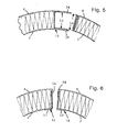
- Fig. 6 shows a further embodiment of the longitudinal edges, wherein overlapping elements are not provided. Rather, the inner shell 2 at both longitudinal edges 12, 14 each have a radially outwardly angled web 40, 41, which are overlapped by two and inwardly angled webs 56-59 of the outer shell 4. Also in this embodiment, the adjacent webs of the inner shell 2 and the outer shell 4 in an expedient manner, in particular by spot welding, firmly connected.
- FIG. 7 the connecting portion of two axially juxtaposed lsollervoruzeen is shown in an axial sectional plane, which are connected by means of an annular clamping and / or holding member 60 tightly and firmly together.
- the clamping and / or holding element 60 is hereinafter referred to simply as a holding element and is designed as a pipe clamp, strap, worm belts or the like, with suitable connection means, such as clamping lever lock, screw or the like are provided.
- the holding element 60 surrounds the axially adjacent and advantageously closely adjacent axial end faces of the two insulating devices over the entire circumferential area coaxial with the longitudinal axis 10.
- connection or closure elements such as screw, clamping lever locks or the like, may be provided which are attached directly to the insulating device.
- connection or closure elements such as screw, clamping lever locks or the like.
- the bendable insulating material 22 advantageously contains an inner insulating filling 62, in particular insulating wadding and / or ceramic fibers, which is surrounded by a substantially closed insulating sleeve 64 or insulating mat, which is advantageously formed as a comparatively dense fabric, in particular of ceramic fibers.
- the insulating material and / or the insulating mat are sufficiently flexible such that the filling into the cavity between the inner shell 2 and the outer shell 4 is easily possible.
- the filling can be carried out expediently with spread longitudinal edges, especially with increasing distance from the longitudinal edges of the distance between the inner shell 2 and the outer shell 4 is increased, so that the insulating material 22 can be introduced without difficulty in the correspondingly enlarged cavity.
- the cavity is preferably free of supports or connecting elements between the inner shell 2 and the outer shell 4.
- the insulating material 22 can be easily replaced. It is known that insulation devices can be expected to decompose the insulating material, in particular due to the high temperatures or vibrations acting on it. Previously known insulation devices with coats tightly and tightly joined by welding, riveting or screwing had to be completely replaced as a result of reduced insulation.
- the insulating device according to the invention only the insulating material 22 is to be exchanged, but otherwise the flexible jacket with the inner jacket 2 and the outer jacket 4 is retained, which are firmly connected to one another exclusively in the region of at least one of the longitudinal edges, preferably on both.
- the axial end faces are open according to the invention and allow the installation and / or removal of the insulating material 22 in a simple manner.
- the insulating material or the insulating mat of the respective sheath projects beyond their axial end edges 66, 68 by a predetermined distance 70.
- the end faces 72, 74 of the insulating material or the insulating mats are close together. It is expressly stated that the insulating materials 22 and the insulating mats are sufficiently flexible and / or elastic. When mounting the insulating these are axially pressed against each other, that in the manner explained the said end faces 72, 74 abut each other sealingly and only then follows the firm connection by means of the holding element 60.
- Fig. 8 shows partly in an axial sectional plane of the end portion of another embodiment of the insulating device
- Fig. 9 shows an axial view in the direction A according to FIG. 8.
- a U-shaped and formed as a ring spacer body 76 is provided at the end edges 66, 68 .
- the radially outer annular ridge 78 bears against the inner surface of the outer jacket 4 and is preferably fixedly connected to it, in particular by spot welding or riveting.
- the radially extending connecting leg 80 as well as the inner leg 82 of the spacer 76 resting against the inner surface of the inner shell 2 include substantially radially directed slots 84 between a plurality of fins 86.
- the spacer 76 may be secured to the inner shell 4 only.
- the distancing body 76 prevents the above-described spreading and the associated change in distance between the inner casing 2 and the outer casing 4 in any way.
- the insulating material 22 bears against the spacer body 76.
- FIG. 8 left not shown end or end portion of the insulating device, however, no spacer body 76 is present, but there protrudes the insulating material according to FIG. 7 on the front edge of the coats 2 and 4 also. If a corresponding insulating element is subsequently arranged on the right with the insulating device according to FIG. 8, then its insulating material bears against the axial end face 88 of the spacer body 76.
- the insulating device may further be formed at both axial ends corresponding Fig. 8 and each having a spacer body 76, further wherein the axially adjoining or subsequent insulating devices in the same manner each contain a spacer body 76 at both ends.
- the clamping and / or holding element is formed in this embodiment as an insulating cover strip or provided with such, so that a free heat transfer is prevented.
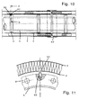
- FIG. 10 A development of the invention is shown in FIG. 10 in an axial sectional plane and further in FIG. 11 partly in a section along section line B according to FIG. 10, wherein the insulating device is shown radially spaced from the flange 8 for clarity.
- the flange 8 includes a pin 90 which engages after assembly in a preferably formed as a slot recess 92 of the inner shell 2.
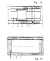
- FIG. 12 another embodiment is shown in an axial sectional plane, wherein the pipeline includes at least one compensator 94 for length compensation.
- the compensator 94 is surrounded by a protective tube 96, on which the inner shell 2 of the insulating device rests.
- the outer diameter of the protective tube 96 expediently corresponds to the outer diameter of the flanges already explained above, so that the individual insulating devices can each have the same inner diameter.
- FIG. 13 A particular embodiment of the insulating device according to the invention is shown in Fig. 13 in an axial sectional plane and in Fig. 14 in an axial view.
- a spacer 98 is arranged, which is here designed as a toothed belt.
- the insulating device is mounted on the tube or its flange and / or the above-described protective tube.
- the spacer 98 serves in a particularly advantageous manner as wear protection, since the insulating device is not directly intercepted indirectly but indirectly via the spacer 98.
- an air cushion is thus present between the tube and the insulating device, which on the one hand promotes the dissipation of the temperature by convection and, on the other hand, represents an insulating layer, as it were.
- Relative movements between the insulating device and the pipe for example as a result of vibrations or changes in length due to temperature changes, can thus not lead to damage to the inner jacket of the insulating device.
- the inner jacket can thus be made comparatively thin, without this affecting the life and ultimately the functioning of the insulating device in any way.
- circumferentially much smaller segments, support plates, bolts or the like may be provided.
- the spacer element 98 Due to the flexibility of the spacer element 98 provided according to the invention, a compensation of manufacturing tolerances is also achieved in a particularly advantageous manner, be it the insulating device or the tube and / or the flanges and / or the protective tubes of the compensators or other components on which the insulating device is supported. Finally, it should be particularly noted that the spacer formed in particular as a toothed belt only results in minimal heat transfer from the pipe or the body to be insulated and the insulating device or its inner jacket.
- Fig. 15 shows a particular embodiment of the longitudinal edges 12, 14 of the insulating device.
- the inner shell 2 has radially outwardly bent webs 100, 102, which partially lie against each other.
- the webs 100 and 102 can be arranged between the webs 100 and 102 in an appropriate manner, an insulating strip which has substantially the same axial length as the insulating device itself.
- the left according to the drawing web 100 with a further web 101 in the direction Angled to the outer shell 4 and firmly connected to this example, by welding or riveting.
- the right according to the drawing web 102 is also bent radially outwardly with a further web 103 substantially at right angles, said web 103 is firmly connected to the outer shell 4 again preferably by welding or riveting.
- the latter web 103 is angled toward the web 101, ie the other longitudinal edge, wherein the webs 101 and 103 facing each other are formed and arranged such that there is a gap 106 between them.
- the web 103 forms with the axial end of the outer shell 4, an overlap element and extends at least approximately to the other, angled web 101 of the associated longitudinal edge 12.
- the gap 106 is particularly suitably designed as a labyrinth gap, so that an undesired heat flow in the region of the longitudinal edges 12, 14 is suppressed.
Landscapes
- Engineering & Computer Science (AREA)
- General Engineering & Computer Science (AREA)
- Mechanical Engineering (AREA)
- Chemical & Material Sciences (AREA)
- Combustion & Propulsion (AREA)
- Thermal Insulation (AREA)
- Exhaust Silencers (AREA)
- Rigid Pipes And Flexible Pipes (AREA)
- Polymers With Sulfur, Phosphorus Or Metals In The Main Chain (AREA)
Claims (10)
- Dispositif d'isolement pour des corps (6) pouvant être traversés par un milieu chaud, en particulier pour des éléments de machine pouvant être traversés par des gaz d'échappement tels que des tuyaux d'échappement ou des dispositifs de chargement, contenant un matériau isolant (22) associé au corps (6), une enveloppe intérieure flexible (2) et une enveloppe extérieure flexible (4) entourant celle-ci et le matériau isolant (22), le dispositif d'isolement étant conformé en unité avec des faces frontales et deux bords longitudinaux (12, 14) mutuellement associés, l'enveloppe intérieure (2) et l'enveloppe extérieure (4) étant reliées l'une à l'autre au moins au niveau d'au moins l'un des bords longitudinaux (12, 14) et le dispositif isolant pouvant être enfilé sur le corps (6) par écartement au niveau des bords longitudinaux (12, 14) se trouvant au moins approximativement l'un contre l'autre après l'enfilage,
caractérisé
en ce que l'enveloppe intérieure (2) et l'enveloppe extérieure (4) sont reliées l'une à l'autre exclusivement au niveau dudit au moins un bord longitudinal (12, 14) au moyen de méplats (40, 42, 44), une cavité (10) étant d'abord présente entre l'enveloppe intérieure (2) et l'enveloppe extérieure (4),
en ce que la cavité (20) prévue pour recevoir le matériau isolant (22) est réalisée ouverte au niveau d'au moins la première face frontale, et
en ce que le matériau isolant (22) est rempli de manière remplaçable dans la cavité (20) entre l'enveloppe extérieure (4) et l'enveloppe intérieure (2). - Dispositif d'isolement selon la revendication 1, caractérisé en ce que l'enveloppe intérieure (2) et l'enveloppe extérieure (4) sont reliées l'une à l'autre exclusivement au niveau des deux bords longitudinaux (12, 14) et/ou en ce que les méplats (40, 42, 44) sont fabriqués par cintrage des bords longitudinaux de l'enveloppe intérieure (2) et/ou de l'enveloppe extérieure (4).
- Dispositif d'isolement selon la revendication 1 ou 2, caractérisé en ce que l'enveloppe intérieure (2) et l'enveloppe extérieure (4) sont composées de tôles métalliques élastiques et/ou en ce que la distance radiale (24) entre les enveloppes (2, 4) sur le pourtour est sensiblement constante, la distance (24) pouvant être augmentée lors de l'écartement des bords longitudinaux (12, 14) pour une distance croissante depuis les bords longitudinaux (12, 14).
- Dispositif d'isolement selon l'une quelconque des revendications 1 à 3, caractérisé en ce que la cavité (20) est réalisée ouverte sur ladite au moins une face frontale sur une plage angulaire d'au moins approximativement 360 degrés.
- Dispositif d'isolement selon l'une quelconque des revendications 1 à 4, caractérisé en ce que le matériau isolant (22) forme saillie axialement sur une distance (70) prédéterminable au niveau d'au moins une face frontale et/ou en ce qu'au niveau d'au moins une face frontale, il est prévu entre l'enveloppe intérieure (2) et l'enveloppe extérieure (4) un corps d'écartement (76) qui est réalisé de préférence en U, une branche de jonction (80) et une branche (82) contenant des lamelles (86) séparées par des fentes (84).
- Dispositif d'isolement selon l'une quelconque des revendications 1 à 5, caractérisé en ce que sur les deux faces frontales est prévu un corps d'écartement (76), et en ce qu'un autre dispositif d'isolement prévu à côté de ce premier dispositif d'isolement présente également au moins un corps d'écartement (76) correspondant, les corps d'écartement (76) des dispositifs d'isolement placés côte à côte étant au moins approximativement l'un contre l'autre dans la zone de jonction et/ou des moyens d'étanchéité étant prévus, en particulier une bande de couverture isolée, et/ou l'élément de serrage ou de maintien (60) étant réalisé hermétique sur tout le pourtour.
- Dispositif d'isolement selon l'une quelconque des revendications 1 à 6, caractérisé en ce que le matériau isolant (22) s'appuie avec une face frontale (72) contre la face frontale (74) du matériau isolant d'un dispositif d'isolement voisin ou contre le corps d'écartement (76) du dispositif d'isolement voisin.
- Dispositif d'isolement selon l'une quelconque des revendications 1 à 7, caractérisé en ce qu'au niveau des bords longitudinaux axiaux (12, 14) mutuellement associés, il est prévu au moins un élément de chevauchement (34, 36) et/ou en ce que l'élément de chevauchement (34, 36) est réalisé d'un seul tenant avec l'enveloppe intérieure (2) ou l'enveloppe extérieure (4) et/ou est formé par des méplats recourbés de l'enveloppe intérieure (2) et/ou de l'enveloppe extérieure (4).
- Dispositif d'isolement selon l'une quelconque des revendications 1 à 8, caractérisé en ce que, pour créer un point fixe, le dispositif d'isolement comprend au moins un évidement (92) qui est conformé de préférence sous la forme d'un trou oblong d'extension sensiblement axiale, et en ce qu'un ergot (90) ou analogue relié au tube (6), en particulier à sa bride (8), s'engage dans l'évidement (92).
- Dispositif d'isolement selon l'une quelconque des revendications 1 à 9, caractérisé en ce que sur la face intérieure de l'enveloppe intérieure (2) est placé au moins un élément d'écartement (98) qui est conformé de préférence en bande dentée et/ou en segment, le dispositif d'isolement s'appuyant par l'intermédiaire dudit au moins un élément d'écartement (98) sur l'élément de machine et/ou le tube (6) et/ou une bride (8) et/ou un tube de protection (6), ledit tube de protection (96) entourant en particulier un compensateur (94).
Applications Claiming Priority (2)
| Application Number | Priority Date | Filing Date | Title |
|---|---|---|---|
| DE10009160A DE10009160A1 (de) | 2000-02-26 | 2000-02-26 | Isoliervorrichtung |
| DE10009160 | 2000-02-26 |
Publications (3)
| Publication Number | Publication Date |
|---|---|
| EP1134478A2 EP1134478A2 (fr) | 2001-09-19 |
| EP1134478A3 EP1134478A3 (fr) | 2003-05-02 |
| EP1134478B1 true EP1134478B1 (fr) | 2006-04-19 |
Family
ID=7632571
Family Applications (1)
| Application Number | Title | Priority Date | Filing Date |
|---|---|---|---|
| EP01103029A Expired - Lifetime EP1134478B1 (fr) | 2000-02-26 | 2001-02-09 | Dispositif d'isolation |
Country Status (4)
| Country | Link |
|---|---|
| EP (1) | EP1134478B1 (fr) |
| AT (1) | ATE323862T1 (fr) |
| DE (2) | DE10009160A1 (fr) |
| ES (1) | ES2259301T3 (fr) |
Cited By (3)
| Publication number | Priority date | Publication date | Assignee | Title |
|---|---|---|---|---|
| EP1840350A2 (fr) | 2006-03-29 | 2007-10-03 | BDD Beteiligungs GmbH | Dispositif de revêtement, en particulier pour tubulures d'échappement d'agrégats |
| DE202007009806U1 (de) | 2007-06-01 | 2008-07-03 | Bdd Beteiligungs Gmbh | Isoliervorrichtung für ein Maschinenelement, insbesondere Abgasrohr |
| EP2241435A1 (fr) | 2009-04-15 | 2010-10-20 | BDD Beteiligungs GmbH | Dispositif d'isolation |
Families Citing this family (1)
| Publication number | Priority date | Publication date | Assignee | Title |
|---|---|---|---|---|
| EP2045451B1 (fr) | 2007-10-01 | 2012-12-12 | BDD Beteiligungs GmbH | Dispositif d'isolation d'un compensateur |
Family Cites Families (8)
| Publication number | Priority date | Publication date | Assignee | Title |
|---|---|---|---|---|
| DE748136C (de) * | 1938-03-18 | 1944-10-27 | Waermeschutzanordnung fuer lotrechte Rohrleitungen oder Behaelter | |
| US3818949A (en) * | 1973-02-05 | 1974-06-25 | Transco Inc | Removable insulated pipe jacket |
| US4584217A (en) * | 1977-09-29 | 1986-04-22 | Morgan Adhesives Company | Composite pressure sensitive adhesive construction |
| DE8307690U1 (de) * | 1983-03-16 | 1983-06-23 | BEMM Ing. Bernd Müller GmbH, 3201 Diekholzen | Isolierung aus schaumstoff fuer zylindrischen speicherbehaelter |
| DE3521467C3 (de) * | 1985-06-14 | 1994-11-17 | Gruenzweig & Hartmann Montage | Rohr zur Leitung von Heißgasen |
| US4823845A (en) * | 1987-09-04 | 1989-04-25 | Manville Corporation | Pipe insulation |
| DE4205427A1 (de) * | 1992-02-22 | 1993-08-26 | Plastorbis Derissen & Mueller | Schale fuer die ummantelung von rohren |
| DE4435718A1 (de) * | 1994-10-06 | 1996-04-11 | Bayer Ag | Rohrleitungssystem mit Überwachungseinrichtung |
-
2000
- 2000-02-26 DE DE10009160A patent/DE10009160A1/de not_active Ceased
-
2001
- 2001-02-09 AT AT01103029T patent/ATE323862T1/de active
- 2001-02-09 DE DE50109523T patent/DE50109523D1/de not_active Expired - Lifetime
- 2001-02-09 EP EP01103029A patent/EP1134478B1/fr not_active Expired - Lifetime
- 2001-02-09 ES ES01103029T patent/ES2259301T3/es not_active Expired - Lifetime
Cited By (5)
| Publication number | Priority date | Publication date | Assignee | Title |
|---|---|---|---|---|
| EP1840350A2 (fr) | 2006-03-29 | 2007-10-03 | BDD Beteiligungs GmbH | Dispositif de revêtement, en particulier pour tubulures d'échappement d'agrégats |
| DE202007009806U1 (de) | 2007-06-01 | 2008-07-03 | Bdd Beteiligungs Gmbh | Isoliervorrichtung für ein Maschinenelement, insbesondere Abgasrohr |
| US8276374B2 (en) | 2007-06-01 | 2012-10-02 | Bdd Beteiligungs Gmbh | Insulating device for a machine element, in particular an exhaust gas pipe |
| EP2241435A1 (fr) | 2009-04-15 | 2010-10-20 | BDD Beteiligungs GmbH | Dispositif d'isolation |
| DE102010015247A1 (de) | 2009-04-15 | 2010-10-21 | Bdd Beteiligungs Gmbh | Isoliervorrichtung |
Also Published As
| Publication number | Publication date |
|---|---|
| ES2259301T3 (es) | 2006-10-01 |
| EP1134478A2 (fr) | 2001-09-19 |
| DE10009160A1 (de) | 2001-09-20 |
| ATE323862T1 (de) | 2006-05-15 |
| EP1134478A3 (fr) | 2003-05-02 |
| DE50109523D1 (de) | 2006-05-24 |
Similar Documents
| Publication | Publication Date | Title |
|---|---|---|
| DE19722603C1 (de) | Leitungselement mit wenigstens zwei Bälgen und einem diese verbindenden Zwischenrohr | |
| EP0615595B1 (fr) | Dispositif de raccordement flexible pour deux elements tubulaires, notamment pour systemes de gaz d'echappement de vehicules | |
| EP0537603B1 (fr) | Tuyau à paroi double, isolé par de l'air, pour des installations d'échappement de véhicules | |
| EP1047865B1 (fr) | Ensemble corps alveolaire presentant une couche intermediaire renfermant au moins une feuille metallique | |
| EP0471175B1 (fr) | Procédé pour la fabrication d'un dispositif pour la purification catalytique ou la décomposition de gaz d'échappement chauds | |
| DE3700070A1 (de) | Vorrichtung fuer die katalytische reinigung von fahrzeugmotor-abgasen | |
| DE3808383A1 (de) | Leitungsverbindung | |
| EP0747582B2 (fr) | Elément de découplage pour les vibrations dans les conduits | |
| EP2807350B1 (fr) | Joint pour un dispositif de retraitement de gaz d'échappement d'un moteur à combustion interne | |
| DE102007016149A1 (de) | Metallschlauchanordnung mit Innen- und Außenschlauch | |
| EP2045451B1 (fr) | Dispositif d'isolation d'un compensateur | |
| DE3427998A1 (de) | Abgasleitung fuer kraftfahrzeugmotoren | |
| EP0816738B1 (fr) | Dispositif de découplement pour vibrations dans conduits | |
| EP0573764B1 (fr) | Joint articulé d'éléments de tube, notamment dans des conduits d'échappement de véhicules automobiles | |
| EP1134478B1 (fr) | Dispositif d'isolation | |
| EP0759502B2 (fr) | Système compensateur | |
| DE102013210982A1 (de) | Dehnkörper zur Verbindung von zwei Rohrstücken insbesondere eines Abgaskanals eines Kraftfahrzeugs sowie Abgasturboladereinheit mit einem derartigen Dehnkörper | |
| DE4212505C1 (en) | Double wall pipe providing intermediate chamber for lambda sensor support - is insulated to prevent loss of heat from exhaust gas of motor vehicle so that catalyser can be effective from cold start | |
| EP0906539B1 (fr) | Isolation pour composants presentant des surfaces exterieures tridimensionnelles | |
| WO2007028428A1 (fr) | Joint plat metallique pour des liaisons sous contrainte thermique entre des conduites de fluide | |
| DE202007004757U1 (de) | Entkoppelelement mit Isolation | |
| EP2894312B1 (fr) | Élément de conduite flexible avec isolation | |
| DE102012216097B4 (de) | Entkoppelelement | |
| DE102009049475B4 (de) | Kompensator für Rohrleitungen | |
| DE102019213718A1 (de) | Hitzeschild und Bauelement mit einem derartigen Hitzeschild |
Legal Events
| Date | Code | Title | Description |
|---|---|---|---|
| PUAI | Public reference made under article 153(3) epc to a published international application that has entered the european phase |
Free format text: ORIGINAL CODE: 0009012 |
|
| AK | Designated contracting states |
Kind code of ref document: A2 Designated state(s): AT BE CH CY DE DK ES FI FR GB GR IE IT LI LU MC NL PT SE TR |
|
| AX | Request for extension of the european patent |
Free format text: AL;LT;LV;MK;RO;SI |
|
| PUAL | Search report despatched |
Free format text: ORIGINAL CODE: 0009013 |
|
| AK | Designated contracting states |
Designated state(s): AT BE CH CY DE DK ES FI FR GB GR IE IT LI LU MC NL PT SE TR |
|
| AX | Request for extension of the european patent |
Extension state: AL LT LV MK RO SI |
|
| 17P | Request for examination filed |
Effective date: 20030523 |
|
| AKX | Designation fees paid |
Designated state(s): AT BE CH CY DE DK ES FI FR GB GR IE IT LI LU MC NL PT SE TR |
|
| 17Q | First examination report despatched |
Effective date: 20040304 |
|
| GRAP | Despatch of communication of intention to grant a patent |
Free format text: ORIGINAL CODE: EPIDOSNIGR1 |
|
| GRAS | Grant fee paid |
Free format text: ORIGINAL CODE: EPIDOSNIGR3 |
|
| GRAA | (expected) grant |
Free format text: ORIGINAL CODE: 0009210 |
|
| AK | Designated contracting states |
Kind code of ref document: B1 Designated state(s): AT BE CH CY DE DK ES FI FR GB GR IE IT LI LU MC NL PT SE TR |
|
| PG25 | Lapsed in a contracting state [announced via postgrant information from national office to epo] |
Ref country code: IT Free format text: LAPSE BECAUSE OF FAILURE TO SUBMIT A TRANSLATION OF THE DESCRIPTION OR TO PAY THE FEE WITHIN THE PRESCRIBED TIME-LIMIT;WARNING: LAPSES OF ITALIAN PATENTS WITH EFFECTIVE DATE BEFORE 2007 MAY HAVE OCCURRED AT ANY TIME BEFORE 2007. THE CORRECT EFFECTIVE DATE MAY BE DIFFERENT FROM THE ONE RECORDED. Effective date: 20060419 Ref country code: FI Free format text: LAPSE BECAUSE OF FAILURE TO SUBMIT A TRANSLATION OF THE DESCRIPTION OR TO PAY THE FEE WITHIN THE PRESCRIBED TIME-LIMIT Effective date: 20060419 Ref country code: IE Free format text: LAPSE BECAUSE OF FAILURE TO SUBMIT A TRANSLATION OF THE DESCRIPTION OR TO PAY THE FEE WITHIN THE PRESCRIBED TIME-LIMIT Effective date: 20060419 |
|
| REG | Reference to a national code |
Ref country code: GB Ref legal event code: FG4D Free format text: NOT ENGLISH |
|
| GBT | Gb: translation of ep patent filed (gb section 77(6)(a)/1977) |
Effective date: 20060419 |
|
| REF | Corresponds to: |
Ref document number: 50109523 Country of ref document: DE Date of ref document: 20060524 Kind code of ref document: P |
|
| REG | Reference to a national code |
Ref country code: IE Ref legal event code: FG4D Free format text: LANGUAGE OF EP DOCUMENT: GERMAN |
|
| PG25 | Lapsed in a contracting state [announced via postgrant information from national office to epo] |
Ref country code: SE Free format text: LAPSE BECAUSE OF FAILURE TO SUBMIT A TRANSLATION OF THE DESCRIPTION OR TO PAY THE FEE WITHIN THE PRESCRIBED TIME-LIMIT Effective date: 20060719 Ref country code: DK Free format text: LAPSE BECAUSE OF FAILURE TO SUBMIT A TRANSLATION OF THE DESCRIPTION OR TO PAY THE FEE WITHIN THE PRESCRIBED TIME-LIMIT Effective date: 20060719 |
|
| PG25 | Lapsed in a contracting state [announced via postgrant information from national office to epo] |
Ref country code: PT Free format text: LAPSE BECAUSE OF FAILURE TO SUBMIT A TRANSLATION OF THE DESCRIPTION OR TO PAY THE FEE WITHIN THE PRESCRIBED TIME-LIMIT Effective date: 20060919 |
|
| REG | Reference to a national code |
Ref country code: ES Ref legal event code: FG2A Ref document number: 2259301 Country of ref document: ES Kind code of ref document: T3 |
|
| ET | Fr: translation filed | ||
| REG | Reference to a national code |
Ref country code: IE Ref legal event code: FD4D |
|
| PLBE | No opposition filed within time limit |
Free format text: ORIGINAL CODE: 0009261 |
|
| STAA | Information on the status of an ep patent application or granted ep patent |
Free format text: STATUS: NO OPPOSITION FILED WITHIN TIME LIMIT |
|
| PG25 | Lapsed in a contracting state [announced via postgrant information from national office to epo] |
Ref country code: MC Free format text: LAPSE BECAUSE OF NON-PAYMENT OF DUE FEES Effective date: 20070228 |
|
| 26N | No opposition filed |
Effective date: 20070122 |
|
| BERE | Be: lapsed |
Owner name: THERMAMAX HOCHTEMPERATURDAMMUNGEN G.M.B.H. Effective date: 20070228 |
|
| PG25 | Lapsed in a contracting state [announced via postgrant information from national office to epo] |
Ref country code: BE Free format text: LAPSE BECAUSE OF NON-PAYMENT OF DUE FEES Effective date: 20070228 |
|
| PG25 | Lapsed in a contracting state [announced via postgrant information from national office to epo] |
Ref country code: GR Free format text: LAPSE BECAUSE OF FAILURE TO SUBMIT A TRANSLATION OF THE DESCRIPTION OR TO PAY THE FEE WITHIN THE PRESCRIBED TIME-LIMIT Effective date: 20060720 |
|
| PG25 | Lapsed in a contracting state [announced via postgrant information from national office to epo] |
Ref country code: LU Free format text: LAPSE BECAUSE OF NON-PAYMENT OF DUE FEES Effective date: 20070209 Ref country code: CY Free format text: LAPSE BECAUSE OF FAILURE TO SUBMIT A TRANSLATION OF THE DESCRIPTION OR TO PAY THE FEE WITHIN THE PRESCRIBED TIME-LIMIT Effective date: 20060419 |
|
| PG25 | Lapsed in a contracting state [announced via postgrant information from national office to epo] |
Ref country code: TR Free format text: LAPSE BECAUSE OF FAILURE TO SUBMIT A TRANSLATION OF THE DESCRIPTION OR TO PAY THE FEE WITHIN THE PRESCRIBED TIME-LIMIT Effective date: 20060419 |
|
| REG | Reference to a national code |
Ref country code: FR Ref legal event code: PLFP Year of fee payment: 15 |
|
| PGFP | Annual fee paid to national office [announced via postgrant information from national office to epo] |
Ref country code: NL Payment date: 20150223 Year of fee payment: 15 |
|
| PGFP | Annual fee paid to national office [announced via postgrant information from national office to epo] |
Ref country code: CH Payment date: 20150223 Year of fee payment: 15 Ref country code: ES Payment date: 20150223 Year of fee payment: 15 Ref country code: DE Payment date: 20150228 Year of fee payment: 15 Ref country code: IT Payment date: 20150224 Year of fee payment: 15 |
|
| PGFP | Annual fee paid to national office [announced via postgrant information from national office to epo] |
Ref country code: FR Payment date: 20150217 Year of fee payment: 15 Ref country code: AT Payment date: 20150218 Year of fee payment: 15 Ref country code: GB Payment date: 20150223 Year of fee payment: 15 |
|
| REG | Reference to a national code |
Ref country code: DE Ref legal event code: R119 Ref document number: 50109523 Country of ref document: DE |
|
| REG | Reference to a national code |
Ref country code: CH Ref legal event code: PL |
|
| REG | Reference to a national code |
Ref country code: AT Ref legal event code: MM01 Ref document number: 323862 Country of ref document: AT Kind code of ref document: T Effective date: 20160209 |
|
| GBPC | Gb: european patent ceased through non-payment of renewal fee |
Effective date: 20160209 |
|
| PG25 | Lapsed in a contracting state [announced via postgrant information from national office to epo] |
Ref country code: CH Free format text: LAPSE BECAUSE OF NON-PAYMENT OF DUE FEES Effective date: 20160229 Ref country code: LI Free format text: LAPSE BECAUSE OF NON-PAYMENT OF DUE FEES Effective date: 20160229 |
|
| REG | Reference to a national code |
Ref country code: NL Ref legal event code: MM Effective date: 20160301 |
|
| REG | Reference to a national code |
Ref country code: FR Ref legal event code: ST Effective date: 20161028 |
|
| PG25 | Lapsed in a contracting state [announced via postgrant information from national office to epo] |
Ref country code: AT Free format text: LAPSE BECAUSE OF NON-PAYMENT OF DUE FEES Effective date: 20160209 |
|
| PG25 | Lapsed in a contracting state [announced via postgrant information from national office to epo] |
Ref country code: IT Free format text: LAPSE BECAUSE OF NON-PAYMENT OF DUE FEES Effective date: 20160209 |
|
| PG25 | Lapsed in a contracting state [announced via postgrant information from national office to epo] |
Ref country code: GB Free format text: LAPSE BECAUSE OF NON-PAYMENT OF DUE FEES Effective date: 20160209 Ref country code: FR Free format text: LAPSE BECAUSE OF NON-PAYMENT OF DUE FEES Effective date: 20160229 Ref country code: DE Free format text: LAPSE BECAUSE OF NON-PAYMENT OF DUE FEES Effective date: 20160901 Ref country code: NL Free format text: LAPSE BECAUSE OF NON-PAYMENT OF DUE FEES Effective date: 20160301 |
|
| PG25 | Lapsed in a contracting state [announced via postgrant information from national office to epo] |
Ref country code: ES Free format text: LAPSE BECAUSE OF NON-PAYMENT OF DUE FEES Effective date: 20160210 |