EP0759502B2 - Système compensateur - Google Patents
Système compensateur Download PDFInfo
- Publication number
- EP0759502B2 EP0759502B2 EP19950112819 EP95112819A EP0759502B2 EP 0759502 B2 EP0759502 B2 EP 0759502B2 EP 19950112819 EP19950112819 EP 19950112819 EP 95112819 A EP95112819 A EP 95112819A EP 0759502 B2 EP0759502 B2 EP 0759502B2
- Authority
- EP
- European Patent Office
- Prior art keywords
- pipe section
- gas
- bridge member
- tight
- pipe
- Prior art date
- Legal status (The legal status is an assumption and is not a legal conclusion. Google has not performed a legal analysis and makes no representation as to the accuracy of the status listed.)
- Expired - Lifetime
Links
Images

Classifications
-
- F—MECHANICAL ENGINEERING; LIGHTING; HEATING; WEAPONS; BLASTING
- F01—MACHINES OR ENGINES IN GENERAL; ENGINE PLANTS IN GENERAL; STEAM ENGINES
- F01N—GAS-FLOW SILENCERS OR EXHAUST APPARATUS FOR MACHINES OR ENGINES IN GENERAL; GAS-FLOW SILENCERS OR EXHAUST APPARATUS FOR INTERNAL-COMBUSTION ENGINES
- F01N13/00—Exhaust or silencing apparatus characterised by constructional features
- F01N13/18—Construction facilitating manufacture, assembly, or disassembly
- F01N13/1805—Fixing exhaust manifolds, exhaust pipes or pipe sections to each other, to engine or to vehicle body
- F01N13/1811—Fixing exhaust manifolds, exhaust pipes or pipe sections to each other, to engine or to vehicle body with means permitting relative movement, e.g. compensation of thermal expansion or vibration
-
- F—MECHANICAL ENGINEERING; LIGHTING; HEATING; WEAPONS; BLASTING
- F01—MACHINES OR ENGINES IN GENERAL; ENGINE PLANTS IN GENERAL; STEAM ENGINES
- F01N—GAS-FLOW SILENCERS OR EXHAUST APPARATUS FOR MACHINES OR ENGINES IN GENERAL; GAS-FLOW SILENCERS OR EXHAUST APPARATUS FOR INTERNAL-COMBUSTION ENGINES
- F01N13/00—Exhaust or silencing apparatus characterised by constructional features
- F01N13/08—Other arrangements or adaptations of exhaust conduits
-
- F—MECHANICAL ENGINEERING; LIGHTING; HEATING; WEAPONS; BLASTING
- F01—MACHINES OR ENGINES IN GENERAL; ENGINE PLANTS IN GENERAL; STEAM ENGINES
- F01N—GAS-FLOW SILENCERS OR EXHAUST APPARATUS FOR MACHINES OR ENGINES IN GENERAL; GAS-FLOW SILENCERS OR EXHAUST APPARATUS FOR INTERNAL-COMBUSTION ENGINES
- F01N13/00—Exhaust or silencing apparatus characterised by constructional features
- F01N13/14—Exhaust or silencing apparatus characterised by constructional features having thermal insulation
-
- F—MECHANICAL ENGINEERING; LIGHTING; HEATING; WEAPONS; BLASTING
- F16—ENGINEERING ELEMENTS AND UNITS; GENERAL MEASURES FOR PRODUCING AND MAINTAINING EFFECTIVE FUNCTIONING OF MACHINES OR INSTALLATIONS; THERMAL INSULATION IN GENERAL
- F16L—PIPES; JOINTS OR FITTINGS FOR PIPES; SUPPORTS FOR PIPES, CABLES OR PROTECTIVE TUBING; MEANS FOR THERMAL INSULATION IN GENERAL
- F16L27/00—Adjustable joints; Joints allowing movement
- F16L27/10—Adjustable joints; Joints allowing movement comprising a flexible connection only
- F16L27/1004—Adjustable joints; Joints allowing movement comprising a flexible connection only introduced in exhaust pipes for hot gases
-
- F—MECHANICAL ENGINEERING; LIGHTING; HEATING; WEAPONS; BLASTING
- F16—ENGINEERING ELEMENTS AND UNITS; GENERAL MEASURES FOR PRODUCING AND MAINTAINING EFFECTIVE FUNCTIONING OF MACHINES OR INSTALLATIONS; THERMAL INSULATION IN GENERAL
- F16L—PIPES; JOINTS OR FITTINGS FOR PIPES; SUPPORTS FOR PIPES, CABLES OR PROTECTIVE TUBING; MEANS FOR THERMAL INSULATION IN GENERAL
- F16L27/00—Adjustable joints; Joints allowing movement
- F16L27/10—Adjustable joints; Joints allowing movement comprising a flexible connection only
- F16L27/107—Adjustable joints; Joints allowing movement comprising a flexible connection only the ends of the pipe being interconnected by a flexible sleeve
- F16L27/11—Adjustable joints; Joints allowing movement comprising a flexible connection only the ends of the pipe being interconnected by a flexible sleeve the sleeve having the form of a bellows with multiple corrugations
-
- F—MECHANICAL ENGINEERING; LIGHTING; HEATING; WEAPONS; BLASTING
- F16—ENGINEERING ELEMENTS AND UNITS; GENERAL MEASURES FOR PRODUCING AND MAINTAINING EFFECTIVE FUNCTIONING OF MACHINES OR INSTALLATIONS; THERMAL INSULATION IN GENERAL
- F16L—PIPES; JOINTS OR FITTINGS FOR PIPES; SUPPORTS FOR PIPES, CABLES OR PROTECTIVE TUBING; MEANS FOR THERMAL INSULATION IN GENERAL
- F16L51/00—Expansion-compensation arrangements for pipe-lines
- F16L51/02—Expansion-compensation arrangements for pipe-lines making use of a bellows or an expansible folded or corrugated tube
- F16L51/025—Expansion-compensation arrangements for pipe-lines making use of a bellows or an expansible folded or corrugated tube with several corrugations
Definitions
- Compensatory orders of the type in question are used in order to take place in all three spatial axes Movements of a limited elastic suspension Internal combustion engine relative to at least one Collect exhaust pipe.
- sliding seat constructions known, however, only a limited lifespan have. Used in these constructions the sliding seat effect the effect of the elastic stretch area of the steel, which, however, with alternating temperature loads only effective for a limited time and therefore not after a certain time is functional.
- the state of the art also includes a compensation arrangement, in which the spaced apart adjacent ends of two one leading hot exhaust gas from an internal combustion engine Pipe sections through a flexible bridge link in Form of a corrugated tube are interconnected.
- the cylindrical ends of the corrugated tube are circumferential the ends of the pipe sections are welded. Between The end face of the pipe sections is a liner pressed.
- the corrugated pipe is covered with a metallic braid encased, which by means of end sleeves on the Pipe sections are defined.
- GB-A 2 125 502 discloses a compensation arrangement, in which a pipe section supplying the exhaust gas over its enlarged in diameter Exhaust gas inlet area together with a cylindrical End section of a bridge member permitted as a corrugated tube in a hole in a mounting flange are attached gas-tight by welding. Further is with the feeding pipe section and the Bridge link an indented end section a sleeve encasing the pontic welded in the hole. The free end of the feeder Pipe section lies in the transition area from the pipe section passing on the exhaust gas a sleeve connected to this pipe section. The The sleeve expands towards the mounting flange. Inside of the largest length section in diameter is the cylindrical end portion of the Bridge member welded.
- the circumference of the im The largest length range of the sleeve is fused a radial flange. Both sides of this radial flange are attenuators or compensators, which of a jacket trapezoidal in cross section be attacked, the at least indirectly part the sleeve welded to the mounting flange.
- the invention is based on the prior art based on the task of a compensation arrangement to create that with simple business education both ensures gas tightness as well absorb axial thermal expansion of the pipe sections can.
- the feed pipe section can be one integral part of the supplying exhaust pipe form. But it can also be a separate component. In this case the end area is larger in diameter of the feeding pipe section on the circumference attached to the supplying exhaust pipe, in particular welded gas-tight. The transition from the larger on the smaller end area is evenly continuous and without sharp edges.
- a radially extending membrane-like radial flange in front This forms an integral part one axially to the forwarding pipe section extending neck.
- the nozzle extends over the End area of the forwarding pipe section and is on this gas-tight, especially by welding, established.
- the circular edge area of the radial flange is also circular, radially extending edge region of a substantially conically shaped support ring connected gastight, which in turn has an axially aligned Spigot on the circumference of the pipe section to be fed attached gastight, especially welded, is.
- Compensating arrangement is its extremely simple structure and a very small installation space with perfect Gas leaks.
- the balancing function of the radial flange the pontic is made according to the features of the claim 2 further improved in that it between the nozzle and the circular edge area is provided with at least one curl.
- the especially circular lid the casing is preferably detachable from the housing assigned. When fixing the lid on Housing become the wire mesh rings and thus also the circular edge areas of the pontic and the support ring in the casing between the Cover and the bottom of the housing fixed in position.
- the pontic is a thin-walled material
- Claim 4 advantageous that for a perfect connection the edge areas of the pontic and the Support ring on the edge of the support ring facing away A weld ring on the side of the pontic is provided.
- the width of the welding ring corresponds then preferably the width of the edge areas.
- the characterized in claim 5 solution of the The object underlying the invention is applied, if one is directly from one on the engine block fixed mounting flange from extending Pipe section as part of an exhaust gas forwarding Exhaust pipe relatively movable to the mounting flange to be oriented.
- the feeding pipe section is comparatively short and cylindrical.
- the forwarding one End section of the feed pipe facing away from the pipe section Pipe section is made together with a cylindrical end portion of a designed as a corrugated tube Bridge member in a hole in the mounting flange, in particular by welding.
- the other end of the pontic which is also is cylindrical, includes the forwarding Pipe section at a distance from the plug area and is preferred here on the outer surface by Welding set.
- the sleeve faces several radially outwards folded webs on axially between the two grasp wire mesh rings one behind the other.
- the wire mesh rings are therefore on the circumference of the sleeve provided and are thus based on this, on the mounting flange or on one of the wire mesh rings surrounding cone housing from that to the mounting flange is welded.
- the forwarding Pipe section forming an air gap is double-walled.
- the forwarding Pipe section forming an air gap is double-walled.
- it is End flange facing away from the mounting flange Bridge member set on the inner tube during the cylindrical end portion of the sleeve on the outer Fixed surface of the outer tube, in particular fixed by welding.
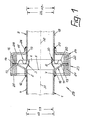
- 1 denotes an exhaust pipe, to an engine block in an unspecified manner an internal combustion engine is connected.
- the end 2 of the exhaust gas supplying exhaust pipe 1 is a pushed from the wall thinner pipe section 3 and with its end region 7 on the outer Surface 4 of the exhaust pipe 1 welded gas-tight.
- End region 6 of the pipe section 3 is in diameter moved in and reaches into the adjacent end area 8 of a pipe section 9 passing on the exhaust gas.
- the game between the bordering end area 6 and the comprehensive end region 8 is dimensioned that even in extreme angular positions of the exhaust pipe 1 no metallic to the forwarding pipe section 9 Contact between the pipe section 3 and the pipe section 9 can take place.
- the inside diameter ID of the exhaust pipe 1 corresponds the inside diameter ID1 of the pipe section 9 and the outer diameter AD of the exhaust pipe 1 corresponds the outer diameter AD1 of the pipe section 9th
- the support ring 11 has a radially extending annular edge region 13 which with a also radially extending annular Edge area 14 of a thin-walled flexible Bridge member 15 is welded gas-tight. To this Purpose is on the edge area 13 of the support ring 11 facing away from the edge region 14 of the bridge member 15 a weld ring 16 is provided. The Width of the weld ring 16 corresponds to the width of the Edge areas 13, 14.
- the bridge member 15 has an axially extending Neck 17 on the outer surface 18 of the forward pipe section 9 welded gas-tight is. Between the nozzle 17 and the The edge flange 14 is the radial flange 19 of the bridge member 15 is provided with a corrugation 20.
- the edge areas 13, 14 of the support ring 11 and Bridge member 15 and the weld ring 16 are between two wire mesh rings 21, 22 clamped lie within a casing 23, which consists of a pot-shaped housing 24 and an annular Lid 25 is composed.
- the pot-shaped housing 24 is with an axially extending neck 26 on the outer surface 18 of the forwarding Pipe section 9 welded.
- the connection is made through the same weld 27 with which the Neck 17 of the bridge member 15 on the outer surface 18 of the pipe section 9 is set
- the wire mesh rings 21, 22 with the help of the cover 25 between this and the bottom 28 of the housing 24 established.
- the compensation arrangement illustrated in FIG. 2 29a includes a rectangular mounting flange 33, which in a manner not shown on a Engine block of an internal combustion engine is fixed.
- the mounting flange 33 has a central bore 34 in which a cylindrical end portion 35 of a bridge member 15a designed as a corrugated tube and an exhaust gas supply cylindrical Pipe section 3a fixed by means of a weld seam 36 are.
- the end region facing away from the fastening flange 33 6a of the pipe section 3a fits into the adjacent one End region 8a of one that forwards the exhaust gas Pipe section 9a with play.
- the game is so big dimensioned that it is also at an incline of the pipe sections 3a and 9a for no metallic contact come between the pipe sections 3a and 9a can.
- the facing away from the mounting flange 33 also cylindrical end portion 37 of the bridge member 15a is by means of a weld 38 on the outer Surface 39 of the pipe section 9a gas-tight attached. In this way, the plug-in area 30a of the pipe sections 3a and 9a gas-tight.
- the bridge member 15a is a sleeve 40 in Distance over which the mounting flange 33 facing end face 41 to the adjacent end face 42 of the mounting flange 33 is distanced.
- the other end 43 of the sleeve 40 is in diameter retracted and cylindrical and by means of a weld 44 on the outer surface 39 of the exhaust pipe section 9a.
- the end area has the sleeve 40 several radially outwards pointing webs 45 with end, to the mounting flange 33 directed legs 46. Both sides the webs 45 are wire mesh rings 21a, 22a.
- a wire mesh ring 21a is through the end face 42 of the Mounting flange 33, the outer surface 47 the sleeve 40, the webs 45 and the legs 46 chambered, while the other wire mesh ring 22a through the outer surface 47 of the sleeve 40, the webs 45 and a cone housing 48 is chambered on the end face 42 of the mounting flange 33 through a weld seam 49 is defined.
- the embodiment of a compensation arrangement 3 differs from that of Figure 2 in that the exhaust gas forwarding Pipe section 9b is double-walled. While the cylindrical facing away from the mounting flange 33 End portion 37 of the bridge member 15a the inner tube 50 is welded, as in the FIG. 2 shows the cylindrical end section 43 the sleeve 40 on the outer surface 51 of the outer tube 52 attached by means of a weld 53. By the double wall becomes an annular gap 54 created, which early cooling of the Exhaust gas prevented.
Landscapes
- Engineering & Computer Science (AREA)
- General Engineering & Computer Science (AREA)
- Mechanical Engineering (AREA)
- Chemical & Material Sciences (AREA)
- Combustion & Propulsion (AREA)
- Exhaust Silencers (AREA)
- Quick-Acting Or Multi-Walled Pipe Joints (AREA)
- Rigid Pipes And Flexible Pipes (AREA)
Claims (6)
- Système compensateur entre deux segments tubulaires (3, 9) agencés en succession, guidant un gaz d'échappement chaud hors d'un moteur à combustion interne et pouvant accomplir des mouvements relatifs limités, l'un par rapport à l'autre, par l'intermédiaire d'une pièce flexible d'entretoisement (15) prévue à l'intérieur d'une enveloppe (23), système dans lequel le segment tubulaire (3) amenant le gaz d'échappement s'engage sans aucun contact, par une région extrême (6) de diamètre réduit, dans la région extrême adjacente (8) du segment tubulaire (9) transférant le gaz d'échappement, et forme au moins indirectement, par la région extrême (7) de diamètre supérieur, un élément constitutif d'une tubulure (1) à gaz d'échappement étanche aux gaz,. caractérisé par le fait que la pièce flexible d'entretoisement (15) s'emboíte par un embout (17) sur la région extrême (8) du segment tubulaire de transfert (9) et est fixée à celui-ci de façon étanche aux gaz, tandis qu'une collerette radiale (19) de la pièce d'entretoisement (15), du type membrane, est appliquée de manière étanche aux gaz, par une région marginale (14) configurée en anneau circulaire, contre une région marginale (13) pareillement configurée en anneau circulaire d'une bague tronconique d'appui (11) fixée avec étanchéité aux gaz, par l'intermédiaire d'un embout (10), sur le pourtour du segment tubulaire d'amenée (3) et en ce que les deux régions marginales (13, 14) en anneaux circulaires sont enserrées entre des bagues (21, 22) à tressages métalliques, prenant au moins partiellement appui contre l'enveloppe (23).
- Système compensateur selon la revendication 1, caractérisé par le fait que la collerette radiale (19) de la pièce d'entretoisement (15) est pourvue d'au moins une ondulation (20) entre l'embout (17) et la région marginale (14).
- Système compensateur selon la revendication 1 ou 2, caractérisé par le fait que l'enveloppe (23) présente un boítier du type cuvette fixé par un embout (26) sur le pourtour du segment tubulaire de transfert (9) et un couvercle (25) pressant les bagues (21, 22) à tressages métalliques contre le fond (28) du boítier (24), s'étendant radialement.
- Système compensateur selon l'une des revendications 1 à 3, caractérisé par le fait qu'une bague (16) rapportée par soudage est prévue sur le côté de la pièce d'entretoisement (15) qui est tourné à l'opposé de la région marginale (13) de la bague d'appui (11).
- Système compensateur entre deux segments tubulaires (3a, 9a) agencés en succession, guidant un gaz d'échappement chaud hors d'un moteur à combustion interne et pouvant accomplir des mouvements relatifs limités, l'un par rapport à l'autre, par l'intermédiaire d'une pièce flexible d'entretoisement (15a) prévue à l'intérieur d'une enveloppe (48), système dans lequel le segment tubulaire (3a) de réalisation cylindrique, amenant le gaz d'échappement, conjointement à une région extrême cylindrique (35) de la pièce d'entretoisement (15a) conçue comme un tube annelé, dans un trou (34) d'une bride de fixation (33), et l'autre région extrême (37) de la pièce d'entretoisement (15a), semblablement cylindrique, sont fixées de manière étanche aux gaz sur le segment tubulaire (9a, 9b) transférant le gaz d'échappement, dans lequel la pièce d'entretoisement (15a),fixée de manière étanche aux gaz sur la surface extérieure (39, 51) de l'extrémité tubulaire (9a, 9b) transférant le gaz d'échappement, est surmontée, à distance, par une douille (40) qui est fixée, par l'intermédiaire d'une région extrême cylindrique (43) de diamètre resserré, tournée à l'opposé de la bride de fixation (33), à la surface extérieure (39, 51) du segment tubulaire de transfert (9a, 9b), et s'enchâsse à l'autre extrémité, par des membrures (45) coudées radialement, entre des bagues (21a, 22a) à tressages métalliques parmi lesquelles une bague (21a) à tressage métallique prend appui contre le côté frontal (42) de la bride de fixation (33), et l'autre bague (22a) à tressage métallique prend appui contre un boítier tronconique formant l'enveloppe (48) et relié à la bride de fixation (33).
- Système compensateur selon la revendication 5, caractérisé par le fait que le segment tubulaire de transfert (9b) est réalisé à double paroi en réservant un interstice (54).
Priority Applications (3)
| Application Number | Priority Date | Filing Date | Title |
|---|---|---|---|
| ES95112819T ES2114713T5 (es) | 1995-08-16 | 1995-08-16 | Disposicion de compensacion. |
| EP19950112819 EP0759502B2 (fr) | 1995-08-16 | 1995-08-16 | Système compensateur |
| DE59501923T DE59501923D1 (de) | 1995-08-16 | 1995-08-16 | Ausgleichsanordnung |
Applications Claiming Priority (1)
| Application Number | Priority Date | Filing Date | Title |
|---|---|---|---|
| EP19950112819 EP0759502B2 (fr) | 1995-08-16 | 1995-08-16 | Système compensateur |
Publications (3)
| Publication Number | Publication Date |
|---|---|
| EP0759502A1 EP0759502A1 (fr) | 1997-02-26 |
| EP0759502B1 EP0759502B1 (fr) | 1998-04-15 |
| EP0759502B2 true EP0759502B2 (fr) | 2003-03-26 |
Family
ID=8219527
Family Applications (1)
| Application Number | Title | Priority Date | Filing Date |
|---|---|---|---|
| EP19950112819 Expired - Lifetime EP0759502B2 (fr) | 1995-08-16 | 1995-08-16 | Système compensateur |
Country Status (3)
| Country | Link |
|---|---|
| EP (1) | EP0759502B2 (fr) |
| DE (1) | DE59501923D1 (fr) |
| ES (1) | ES2114713T5 (fr) |
Families Citing this family (12)
| Publication number | Priority date | Publication date | Assignee | Title |
|---|---|---|---|---|
| FR2833312A1 (fr) * | 2001-12-11 | 2003-06-13 | Qualetude | Dispositif de recyclage de gaz d'echappement pour moteur a combustion interne |
| DE102004047418B4 (de) * | 2004-09-28 | 2007-03-15 | Benteler Automobiltechnik Gmbh | Ausgleichsanordnung |
| DE102004053916B4 (de) | 2004-11-05 | 2012-03-08 | Benteler Automobiltechnik Gmbh | Abgasleitung sowie Verfahren zur Herstellung einer Abgasleitung |
| DE102004054441B4 (de) * | 2004-11-10 | 2006-08-03 | J. Eberspächer GmbH & Co. KG | Schalldämpfer |
| GB2563084B (en) * | 2017-06-03 | 2022-04-27 | Polar Tech Management Group Limited | Finisher component and assembly incorporating same |
| DE102019126364A1 (de) * | 2019-09-30 | 2021-04-01 | Umfotec Gmbh | Lagerbuchse und Verfahren zur Herstellung einer Lagerbuchse |
| DE102019131891A1 (de) * | 2019-11-26 | 2021-05-27 | Eberspächer Exhaust Technology GmbH | Verbindungseinheit |
| CN110921332B (zh) * | 2019-12-17 | 2021-07-20 | 陕西延长石油(集团)有限责任公司 | 一种粉体输送通道连接结构及方法 |
| DE102021210832A1 (de) * | 2021-09-28 | 2023-03-30 | Robert Bosch Gesellschaft mit beschränkter Haftung | Wärmedehnungsausgleichsvorrichtung und Hochtemperaturkomponente mit einer solchen Wärmedehnungsausgleichsvorrichtung |
| CN115126956B (zh) * | 2022-07-28 | 2025-02-07 | 德阳东汽电站机械制造有限公司 | 一种非金属膨胀节及其生产方法 |
| CN116557670B (zh) * | 2023-04-26 | 2023-10-31 | 南京晨光东螺波纹管有限公司 | 一种弹性减振的波纹管装置 |
| CN116638305B (zh) * | 2023-07-17 | 2025-12-26 | 西安理工大学 | 无接触装配辅助装置 |
Family Cites Families (10)
| Publication number | Priority date | Publication date | Assignee | Title |
|---|---|---|---|---|
| US4659117A (en) * | 1982-08-10 | 1987-04-21 | Iwk Regler Und Kompensatoren Gmbh | Flexible coupling for pipes in exhaust systems of motor vehicles |
| DE8222490U1 (de) * | 1982-08-10 | 1982-11-11 | IWK Regler und Kompensatoren GmbH, 7513 Stutensee | Einrichtung zum gelenkigen verbinden von motor und abgasanlage |
| EP0208128B1 (fr) * | 1985-07-12 | 1990-02-07 | Witzenmann GmbH Metallschlauch-Fabrik Pforzheim | Connexion articulée d'éléments de tube, notamment dans des conduits d'échappement de véhicules automobiles |
| DE3911114A1 (de) * | 1989-04-06 | 1990-10-18 | Iwk Regler Kompensatoren | Vorrichtung zur entkoppelung zweier rohrteile |
| DE3915838A1 (de) * | 1989-05-16 | 1990-11-22 | Witzenmann Metallschlauchfab | Verbindung zweier rohre einer leitung fuer heisse medien |
| US5331810A (en) * | 1992-05-21 | 1994-07-26 | Arvin Industries, Inc. | Low thermal capacitance exhaust system for an internal combustion engine |
| DE9212855U1 (de) * | 1992-09-24 | 1992-11-19 | IWK Regler und Kompensatoren GmbH, 7513 Stutensee | Gelenkige Verbindung von Rohrteilen, insbesondere bei Abgasleitungen von Kraftfahrzeugen |
| DE4233644C2 (de) * | 1992-10-06 | 1994-08-18 | Burgmann Dichtungswerk Feodor | Flexible Verbindungsanordnung für zwei Rohrteile, insbesondere bei Abgasanlagen von Kraftfahrzeugen |
| DE9301772U1 (de) * | 1993-02-09 | 1993-03-25 | IWK Regler und Kompensatoren GmbH, 76297 Stutensee | Gelenkige Verbindung von Rohrteilen |
| DE4317334C2 (de) * | 1993-05-25 | 2003-09-25 | Iwka Balg Und Kompensatoren Te | Vorrichtung zum flexiblen Verbinden von Rohren in Abgasleitungen von Kraftfahrzeugen |
-
1995
- 1995-08-16 DE DE59501923T patent/DE59501923D1/de not_active Expired - Lifetime
- 1995-08-16 ES ES95112819T patent/ES2114713T5/es not_active Expired - Lifetime
- 1995-08-16 EP EP19950112819 patent/EP0759502B2/fr not_active Expired - Lifetime
Also Published As
| Publication number | Publication date |
|---|---|
| EP0759502A1 (fr) | 1997-02-26 |
| DE59501923D1 (de) | 1998-05-20 |
| ES2114713T5 (es) | 2003-11-16 |
| EP0759502B1 (fr) | 1998-04-15 |
| ES2114713T3 (es) | 1998-06-01 |
Similar Documents
| Publication | Publication Date | Title |
|---|---|---|
| EP0759502B2 (fr) | Système compensateur | |
| EP0580963B1 (fr) | Conduite articulée | |
| EP1504231A1 (fr) | Echangeur de chaleur de gaz d'echappement, destine en particulier a un vehicule automobile | |
| DE2401455A1 (de) | Behaelter fuer katalysatoren zur steuerung und kontrolle der abgasemission bei brennkraftmaschinen und verfahren zu deren fertigung | |
| EP3420255A1 (fr) | Raccord et module de gestion de chaleur pourvu d'un tel raccord | |
| EP0508145B1 (fr) | Conduit d'échappement isolé par une couche d'air | |
| EP0022063A1 (fr) | Dispositif d'évacuation des gaz d'échappement pour moteurs à combustion interne et procédé pour sa fabrication | |
| EP0681097B1 (fr) | Elément de connexion flexible pour éléments tubulaires | |
| EP1048881B1 (fr) | Conduite de produit réfrigérant pour conditionneurs d'air | |
| DE10023149A1 (de) | Hochdruckkraftstoffeinspritzrohr für Dieselmotoren | |
| DE3427998A1 (de) | Abgasleitung fuer kraftfahrzeugmotoren | |
| DE19606003A1 (de) | Schiebesitz-Rohrverbindung | |
| DE2020154B2 (de) | Vorrichtung zum reinigen der abgase von brennkraftmaschinen | |
| EP0747582A2 (fr) | Elément de découplage pour les vibrations dans les conduits | |
| DE69603024T2 (de) | Kompensator und schwingungsdämpfer aus metall für rohrleitungssysteme | |
| EP0575727A1 (fr) | Joint de tuyau | |
| DE69703856T2 (de) | Kupplung für zwei Metallrohre | |
| GB2054042A (en) | Hydraulic cylinder assembly | |
| DE102013210982A1 (de) | Dehnkörper zur Verbindung von zwei Rohrstücken insbesondere eines Abgaskanals eines Kraftfahrzeugs sowie Abgasturboladereinheit mit einem derartigen Dehnkörper | |
| DE4212505C1 (en) | Double wall pipe providing intermediate chamber for lambda sensor support - is insulated to prevent loss of heat from exhaust gas of motor vehicle so that catalyser can be effective from cold start | |
| EP0889271B1 (fr) | Raccord entre deux tuyaux emboítés | |
| DE3603498C2 (fr) | ||
| DE4244315C2 (de) | Katalytische Abgasreinigungsvorrichtung | |
| EP2894312B1 (fr) | Élément de conduite flexible avec isolation | |
| EP1134478B1 (fr) | Dispositif d'isolation |
Legal Events
| Date | Code | Title | Description |
|---|---|---|---|
| PUAI | Public reference made under article 153(3) epc to a published international application that has entered the european phase |
Free format text: ORIGINAL CODE: 0009012 |
|
| 17P | Request for examination filed |
Effective date: 19960129 |
|
| AK | Designated contracting states |
Kind code of ref document: A1 Designated state(s): DE ES FR GB IT PT SE |
|
| 17Q | First examination report despatched |
Effective date: 19970312 |
|
| GRAG | Despatch of communication of intention to grant |
Free format text: ORIGINAL CODE: EPIDOS AGRA |
|
| GRAG | Despatch of communication of intention to grant |
Free format text: ORIGINAL CODE: EPIDOS AGRA |
|
| GRAH | Despatch of communication of intention to grant a patent |
Free format text: ORIGINAL CODE: EPIDOS IGRA |
|
| GRAH | Despatch of communication of intention to grant a patent |
Free format text: ORIGINAL CODE: EPIDOS IGRA |
|
| GRAA | (expected) grant |
Free format text: ORIGINAL CODE: 0009210 |
|
| ITF | It: translation for a ep patent filed | ||
| AK | Designated contracting states |
Kind code of ref document: B1 Designated state(s): DE ES FR GB IT PT SE |
|
| GBT | Gb: translation of ep patent filed (gb section 77(6)(a)/1977) |
Effective date: 19980415 |
|
| REF | Corresponds to: |
Ref document number: 59501923 Country of ref document: DE Date of ref document: 19980520 |
|
| REG | Reference to a national code |
Ref country code: ES Ref legal event code: FG2A Ref document number: 2114713 Country of ref document: ES Kind code of ref document: T3 |
|
| REG | Reference to a national code |
Ref country code: PT Ref legal event code: SC4A Free format text: AVAILABILITY OF NATIONAL TRANSLATION Effective date: 19980416 |
|
| ET | Fr: translation filed | ||
| PLBQ | Unpublished change to opponent data |
Free format text: ORIGINAL CODE: EPIDOS OPPO |
|
| PLBI | Opposition filed |
Free format text: ORIGINAL CODE: 0009260 |
|
| 26 | Opposition filed |
Opponent name: IWK REGLER + KOMPENSATOREN GMBH Effective date: 19981024 |
|
| PLBF | Reply of patent proprietor to notice(s) of opposition |
Free format text: ORIGINAL CODE: EPIDOS OBSO |
|
| PLBF | Reply of patent proprietor to notice(s) of opposition |
Free format text: ORIGINAL CODE: EPIDOS OBSO |
|
| PLBO | Opposition rejected |
Free format text: ORIGINAL CODE: EPIDOS REJO |
|
| APAC | Appeal dossier modified |
Free format text: ORIGINAL CODE: EPIDOS NOAPO |
|
| APAE | Appeal reference modified |
Free format text: ORIGINAL CODE: EPIDOS REFNO |
|
| APAC | Appeal dossier modified |
Free format text: ORIGINAL CODE: EPIDOS NOAPO |
|
| REG | Reference to a national code |
Ref country code: GB Ref legal event code: IF02 |
|
| APAC | Appeal dossier modified |
Free format text: ORIGINAL CODE: EPIDOS NOAPO |
|
| PLAW | Interlocutory decision in opposition |
Free format text: ORIGINAL CODE: EPIDOS IDOP |
|
| PUAH | Patent maintained in amended form |
Free format text: ORIGINAL CODE: 0009272 |
|
| STAA | Information on the status of an ep patent application or granted ep patent |
Free format text: STATUS: PATENT MAINTAINED AS AMENDED |
|
| 27A | Patent maintained in amended form |
Effective date: 20030326 |
|
| AK | Designated contracting states |
Designated state(s): DE ES FR GB IT PT SE |
|
| GBTA | Gb: translation of amended ep patent filed (gb section 77(6)(b)/1977) |
Effective date: 20030502 |
|
| REG | Reference to a national code |
Ref country code: SE Ref legal event code: RPEO |
|
| REG | Reference to a national code |
Ref country code: ES Ref legal event code: DC2A Date of ref document: 20030528 Kind code of ref document: T5 |
|
| ET3 | Fr: translation filed ** decision concerning opposition | ||
| PGFP | Annual fee paid to national office [announced via postgrant information from national office to epo] |
Ref country code: PT Payment date: 20040617 Year of fee payment: 10 |
|
| PGFP | Annual fee paid to national office [announced via postgrant information from national office to epo] |
Ref country code: ES Payment date: 20040715 Year of fee payment: 10 |
|
| PGFP | Annual fee paid to national office [announced via postgrant information from national office to epo] |
Ref country code: SE Payment date: 20040806 Year of fee payment: 10 |
|
| PGFP | Annual fee paid to national office [announced via postgrant information from national office to epo] |
Ref country code: GB Payment date: 20040811 Year of fee payment: 10 |
|
| PG25 | Lapsed in a contracting state [announced via postgrant information from national office to epo] |
Ref country code: IT Free format text: LAPSE BECAUSE OF NON-PAYMENT OF DUE FEES;WARNING: LAPSES OF ITALIAN PATENTS WITH EFFECTIVE DATE BEFORE 2007 MAY HAVE OCCURRED AT ANY TIME BEFORE 2007. THE CORRECT EFFECTIVE DATE MAY BE DIFFERENT FROM THE ONE RECORDED. Effective date: 20050816 Ref country code: GB Free format text: LAPSE BECAUSE OF NON-PAYMENT OF DUE FEES Effective date: 20050816 |
|
| PG25 | Lapsed in a contracting state [announced via postgrant information from national office to epo] |
Ref country code: SE Free format text: LAPSE BECAUSE OF NON-PAYMENT OF DUE FEES Effective date: 20050817 Ref country code: ES Free format text: LAPSE BECAUSE OF NON-PAYMENT OF DUE FEES Effective date: 20050817 |
|
| APAH | Appeal reference modified |
Free format text: ORIGINAL CODE: EPIDOSCREFNO |
|
| PG25 | Lapsed in a contracting state [announced via postgrant information from national office to epo] |
Ref country code: PT Free format text: LAPSE BECAUSE OF NON-PAYMENT OF DUE FEES Effective date: 20060216 |
|
| EUG | Se: european patent has lapsed | ||
| GBPC | Gb: european patent ceased through non-payment of renewal fee |
Effective date: 20050816 |
|
| REG | Reference to a national code |
Ref country code: ES Ref legal event code: FD2A Effective date: 20050817 |
|
| PLAB | Opposition data, opponent's data or that of the opponent's representative modified |
Free format text: ORIGINAL CODE: 0009299OPPO |
|
| PGFP | Annual fee paid to national office [announced via postgrant information from national office to epo] |
Ref country code: DE Payment date: 20120629 Year of fee payment: 18 Ref country code: FR Payment date: 20120906 Year of fee payment: 18 |
|
| REG | Reference to a national code |
Ref country code: DE Ref legal event code: R119 Ref document number: 59501923 Country of ref document: DE |
|
| PG25 | Lapsed in a contracting state [announced via postgrant information from national office to epo] |
Ref country code: DE Free format text: LAPSE BECAUSE OF NON-PAYMENT OF DUE FEES Effective date: 20140301 |
|
| REG | Reference to a national code |
Ref country code: FR Ref legal event code: ST Effective date: 20140430 |
|
| REG | Reference to a national code |
Ref country code: DE Ref legal event code: R079 Ref document number: 59501923 Country of ref document: DE Free format text: PREVIOUS MAIN CLASS: F01N0007180000 Ipc: F01N0013180000 |
|
| REG | Reference to a national code |
Ref country code: DE Ref legal event code: R119 Ref document number: 59501923 Country of ref document: DE Effective date: 20140301 Ref country code: DE Ref legal event code: R079 Ref document number: 59501923 Country of ref document: DE Free format text: PREVIOUS MAIN CLASS: F01N0007180000 Ipc: F01N0013180000 Effective date: 20140526 |
|
| PG25 | Lapsed in a contracting state [announced via postgrant information from national office to epo] |
Ref country code: FR Free format text: LAPSE BECAUSE OF NON-PAYMENT OF DUE FEES Effective date: 20130902 |