EP1134525B1 - Procédé de production d'azote liquide et gazeux avec une quantité variable de liquide - Google Patents
Procédé de production d'azote liquide et gazeux avec une quantité variable de liquide Download PDFInfo
- Publication number
- EP1134525B1 EP1134525B1 EP01106637A EP01106637A EP1134525B1 EP 1134525 B1 EP1134525 B1 EP 1134525B1 EP 01106637 A EP01106637 A EP 01106637A EP 01106637 A EP01106637 A EP 01106637A EP 1134525 B1 EP1134525 B1 EP 1134525B1
- Authority
- EP
- European Patent Office
- Prior art keywords
- column
- oxygen
- nitrogen
- liquid
- condenser
- Prior art date
- Legal status (The legal status is an assumption and is not a legal conclusion. Google has not performed a legal analysis and makes no representation as to the accuracy of the status listed.)
- Expired - Lifetime
Links
- IJGRMHOSHXDMSA-UHFFFAOYSA-N Atomic nitrogen Chemical compound N#N IJGRMHOSHXDMSA-UHFFFAOYSA-N 0.000 title claims abstract description 238
- 229910052757 nitrogen Inorganic materials 0.000 title claims abstract description 119
- 239000007788 liquid Substances 0.000 title claims abstract description 85
- 238000000034 method Methods 0.000 title claims abstract description 49
- 230000008569 process Effects 0.000 title claims abstract description 29
- 239000001301 oxygen Substances 0.000 claims abstract description 85
- 229910052760 oxygen Inorganic materials 0.000 claims abstract description 85
- QVGXLLKOCUKJST-UHFFFAOYSA-N atomic oxygen Chemical compound [O] QVGXLLKOCUKJST-UHFFFAOYSA-N 0.000 claims abstract description 81
- 239000007789 gas Substances 0.000 claims abstract description 58
- 239000000047 product Substances 0.000 claims abstract description 48
- MYMOFIZGZYHOMD-UHFFFAOYSA-N Dioxygen Chemical compound O=O MYMOFIZGZYHOMD-UHFFFAOYSA-N 0.000 claims abstract description 47
- 238000004821 distillation Methods 0.000 claims abstract description 28
- 239000012263 liquid product Substances 0.000 claims abstract description 21
- 230000008016 vaporization Effects 0.000 claims abstract 16
- 239000012535 impurity Substances 0.000 claims description 7
- 238000010992 reflux Methods 0.000 claims description 3
- 238000009834 vaporization Methods 0.000 claims 9
- 230000001174 ascending effect Effects 0.000 claims 2
- 238000005194 fractionation Methods 0.000 claims 2
- 238000010438 heat treatment Methods 0.000 abstract description 6
- 238000001816 cooling Methods 0.000 abstract description 5
- 239000006200 vaporizer Substances 0.000 abstract 8
- 238000000354 decomposition reaction Methods 0.000 abstract 2
- 238000001704 evaporation Methods 0.000 description 28
- 230000008020 evaporation Effects 0.000 description 28
- 238000004519 manufacturing process Methods 0.000 description 14
- 230000006835 compression Effects 0.000 description 5
- 238000007906 compression Methods 0.000 description 5
- 239000001307 helium Substances 0.000 description 5
- 229910052734 helium Inorganic materials 0.000 description 5
- SWQJXJOGLNCZEY-UHFFFAOYSA-N helium atom Chemical compound [He] SWQJXJOGLNCZEY-UHFFFAOYSA-N 0.000 description 5
- 238000004172 nitrogen cycle Methods 0.000 description 5
- 229910052754 neon Inorganic materials 0.000 description 4
- GKAOGPIIYCISHV-UHFFFAOYSA-N neon atom Chemical compound [Ne] GKAOGPIIYCISHV-UHFFFAOYSA-N 0.000 description 4
- 230000000630 rising effect Effects 0.000 description 4
- UFHFLCQGNIYNRP-UHFFFAOYSA-N Hydrogen Chemical compound [H][H] UFHFLCQGNIYNRP-UHFFFAOYSA-N 0.000 description 3
- 238000010586 diagram Methods 0.000 description 3
- 239000001257 hydrogen Substances 0.000 description 3
- 229910052739 hydrogen Inorganic materials 0.000 description 3
- 238000011084 recovery Methods 0.000 description 3
- 238000000926 separation method Methods 0.000 description 3
- XKRFYHLGVUSROY-UHFFFAOYSA-N Argon Chemical compound [Ar] XKRFYHLGVUSROY-UHFFFAOYSA-N 0.000 description 2
- 238000004887 air purification Methods 0.000 description 2
- 230000007423 decrease Effects 0.000 description 2
- 230000002349 favourable effect Effects 0.000 description 2
- 239000000203 mixture Substances 0.000 description 2
- 238000010926 purge Methods 0.000 description 2
- 238000011144 upstream manufacturing Methods 0.000 description 2
- 229910052786 argon Inorganic materials 0.000 description 1
- 230000008901 benefit Effects 0.000 description 1
- 238000009835 boiling Methods 0.000 description 1
- 239000006227 byproduct Substances 0.000 description 1
- 239000003990 capacitor Substances 0.000 description 1
- 230000008859 change Effects 0.000 description 1
- 238000005056 compaction Methods 0.000 description 1
- 239000000356 contaminant Substances 0.000 description 1
- 125000004122 cyclic group Chemical group 0.000 description 1
- 229930195733 hydrocarbon Natural products 0.000 description 1
- 150000002430 hydrocarbons Chemical class 0.000 description 1
- 238000009434 installation Methods 0.000 description 1
- 229910052743 krypton Inorganic materials 0.000 description 1
- DNNSSWSSYDEUBZ-UHFFFAOYSA-N krypton atom Chemical compound [Kr] DNNSSWSSYDEUBZ-UHFFFAOYSA-N 0.000 description 1
- 230000004048 modification Effects 0.000 description 1
- 238000012986 modification Methods 0.000 description 1
- DOTMOQHOJINYBL-UHFFFAOYSA-N molecular nitrogen;molecular oxygen Chemical compound N#N.O=O DOTMOQHOJINYBL-UHFFFAOYSA-N 0.000 description 1
- 239000002808 molecular sieve Substances 0.000 description 1
- 238000005191 phase separation Methods 0.000 description 1
- 230000009467 reduction Effects 0.000 description 1
- 239000003507 refrigerant Substances 0.000 description 1
- 238000005057 refrigeration Methods 0.000 description 1
- 230000008929 regeneration Effects 0.000 description 1
- 238000011069 regeneration method Methods 0.000 description 1
- 230000001105 regulatory effect Effects 0.000 description 1
- 230000003014 reinforcing effect Effects 0.000 description 1
- 230000002040 relaxant effect Effects 0.000 description 1
- URGAHOPLAPQHLN-UHFFFAOYSA-N sodium aluminosilicate Chemical compound [Na+].[Al+3].[O-][Si]([O-])=O.[O-][Si]([O-])=O URGAHOPLAPQHLN-UHFFFAOYSA-N 0.000 description 1
- 238000010792 warming Methods 0.000 description 1
- 229910052724 xenon Inorganic materials 0.000 description 1
- FHNFHKCVQCLJFQ-UHFFFAOYSA-N xenon atom Chemical compound [Xe] FHNFHKCVQCLJFQ-UHFFFAOYSA-N 0.000 description 1
Images


Classifications
-
- F—MECHANICAL ENGINEERING; LIGHTING; HEATING; WEAPONS; BLASTING
- F25—REFRIGERATION OR COOLING; COMBINED HEATING AND REFRIGERATION SYSTEMS; HEAT PUMP SYSTEMS; MANUFACTURE OR STORAGE OF ICE; LIQUEFACTION SOLIDIFICATION OF GASES
- F25J—LIQUEFACTION, SOLIDIFICATION OR SEPARATION OF GASES OR GASEOUS OR LIQUEFIED GASEOUS MIXTURES BY PRESSURE AND COLD TREATMENT OR BY BRINGING THEM INTO THE SUPERCRITICAL STATE
- F25J3/00—Processes or apparatus for separating the constituents of gaseous or liquefied gaseous mixtures involving the use of liquefaction or solidification
- F25J3/02—Processes or apparatus for separating the constituents of gaseous or liquefied gaseous mixtures involving the use of liquefaction or solidification by rectification, i.e. by continuous interchange of heat and material between a vapour stream and a liquid stream
- F25J3/04—Processes or apparatus for separating the constituents of gaseous or liquefied gaseous mixtures involving the use of liquefaction or solidification by rectification, i.e. by continuous interchange of heat and material between a vapour stream and a liquid stream for air
- F25J3/04763—Start-up or control of the process; Details of the apparatus used
- F25J3/04769—Operation, control and regulation of the process; Instrumentation within the process
- F25J3/04854—Safety aspects of operation
- F25J3/0486—Safety aspects of operation of vaporisers for oxygen enriched liquids, e.g. purging of liquids
-
- F—MECHANICAL ENGINEERING; LIGHTING; HEATING; WEAPONS; BLASTING
- F25—REFRIGERATION OR COOLING; COMBINED HEATING AND REFRIGERATION SYSTEMS; HEAT PUMP SYSTEMS; MANUFACTURE OR STORAGE OF ICE; LIQUEFACTION SOLIDIFICATION OF GASES
- F25J—LIQUEFACTION, SOLIDIFICATION OR SEPARATION OF GASES OR GASEOUS OR LIQUEFIED GASEOUS MIXTURES BY PRESSURE AND COLD TREATMENT OR BY BRINGING THEM INTO THE SUPERCRITICAL STATE
- F25J3/00—Processes or apparatus for separating the constituents of gaseous or liquefied gaseous mixtures involving the use of liquefaction or solidification
- F25J3/02—Processes or apparatus for separating the constituents of gaseous or liquefied gaseous mixtures involving the use of liquefaction or solidification by rectification, i.e. by continuous interchange of heat and material between a vapour stream and a liquid stream
- F25J3/04—Processes or apparatus for separating the constituents of gaseous or liquefied gaseous mixtures involving the use of liquefaction or solidification by rectification, i.e. by continuous interchange of heat and material between a vapour stream and a liquid stream for air
- F25J3/04006—Providing pressurised feed air or process streams within or from the air fractionation unit
- F25J3/04012—Providing pressurised feed air or process streams within or from the air fractionation unit by compression of warm gaseous streams; details of intake or interstage cooling
- F25J3/04018—Providing pressurised feed air or process streams within or from the air fractionation unit by compression of warm gaseous streams; details of intake or interstage cooling of main feed air
-
- F—MECHANICAL ENGINEERING; LIGHTING; HEATING; WEAPONS; BLASTING
- F25—REFRIGERATION OR COOLING; COMBINED HEATING AND REFRIGERATION SYSTEMS; HEAT PUMP SYSTEMS; MANUFACTURE OR STORAGE OF ICE; LIQUEFACTION SOLIDIFICATION OF GASES
- F25J—LIQUEFACTION, SOLIDIFICATION OR SEPARATION OF GASES OR GASEOUS OR LIQUEFIED GASEOUS MIXTURES BY PRESSURE AND COLD TREATMENT OR BY BRINGING THEM INTO THE SUPERCRITICAL STATE
- F25J3/00—Processes or apparatus for separating the constituents of gaseous or liquefied gaseous mixtures involving the use of liquefaction or solidification
- F25J3/02—Processes or apparatus for separating the constituents of gaseous or liquefied gaseous mixtures involving the use of liquefaction or solidification by rectification, i.e. by continuous interchange of heat and material between a vapour stream and a liquid stream
- F25J3/04—Processes or apparatus for separating the constituents of gaseous or liquefied gaseous mixtures involving the use of liquefaction or solidification by rectification, i.e. by continuous interchange of heat and material between a vapour stream and a liquid stream for air
- F25J3/04006—Providing pressurised feed air or process streams within or from the air fractionation unit
- F25J3/04012—Providing pressurised feed air or process streams within or from the air fractionation unit by compression of warm gaseous streams; details of intake or interstage cooling
- F25J3/0403—Providing pressurised feed air or process streams within or from the air fractionation unit by compression of warm gaseous streams; details of intake or interstage cooling of nitrogen
-
- F—MECHANICAL ENGINEERING; LIGHTING; HEATING; WEAPONS; BLASTING
- F25—REFRIGERATION OR COOLING; COMBINED HEATING AND REFRIGERATION SYSTEMS; HEAT PUMP SYSTEMS; MANUFACTURE OR STORAGE OF ICE; LIQUEFACTION SOLIDIFICATION OF GASES
- F25J—LIQUEFACTION, SOLIDIFICATION OR SEPARATION OF GASES OR GASEOUS OR LIQUEFIED GASEOUS MIXTURES BY PRESSURE AND COLD TREATMENT OR BY BRINGING THEM INTO THE SUPERCRITICAL STATE
- F25J3/00—Processes or apparatus for separating the constituents of gaseous or liquefied gaseous mixtures involving the use of liquefaction or solidification
- F25J3/02—Processes or apparatus for separating the constituents of gaseous or liquefied gaseous mixtures involving the use of liquefaction or solidification by rectification, i.e. by continuous interchange of heat and material between a vapour stream and a liquid stream
- F25J3/04—Processes or apparatus for separating the constituents of gaseous or liquefied gaseous mixtures involving the use of liquefaction or solidification by rectification, i.e. by continuous interchange of heat and material between a vapour stream and a liquid stream for air
- F25J3/04006—Providing pressurised feed air or process streams within or from the air fractionation unit
- F25J3/04078—Providing pressurised feed air or process streams within or from the air fractionation unit providing pressurized products by liquid compression and vaporisation with cold recovery, i.e. so-called internal compression
- F25J3/0409—Providing pressurised feed air or process streams within or from the air fractionation unit providing pressurized products by liquid compression and vaporisation with cold recovery, i.e. so-called internal compression of oxygen
-
- F—MECHANICAL ENGINEERING; LIGHTING; HEATING; WEAPONS; BLASTING
- F25—REFRIGERATION OR COOLING; COMBINED HEATING AND REFRIGERATION SYSTEMS; HEAT PUMP SYSTEMS; MANUFACTURE OR STORAGE OF ICE; LIQUEFACTION SOLIDIFICATION OF GASES
- F25J—LIQUEFACTION, SOLIDIFICATION OR SEPARATION OF GASES OR GASEOUS OR LIQUEFIED GASEOUS MIXTURES BY PRESSURE AND COLD TREATMENT OR BY BRINGING THEM INTO THE SUPERCRITICAL STATE
- F25J3/00—Processes or apparatus for separating the constituents of gaseous or liquefied gaseous mixtures involving the use of liquefaction or solidification
- F25J3/02—Processes or apparatus for separating the constituents of gaseous or liquefied gaseous mixtures involving the use of liquefaction or solidification by rectification, i.e. by continuous interchange of heat and material between a vapour stream and a liquid stream
- F25J3/04—Processes or apparatus for separating the constituents of gaseous or liquefied gaseous mixtures involving the use of liquefaction or solidification by rectification, i.e. by continuous interchange of heat and material between a vapour stream and a liquid stream for air
- F25J3/04006—Providing pressurised feed air or process streams within or from the air fractionation unit
- F25J3/04109—Arrangements of compressors and /or their drivers
- F25J3/04145—Mechanically coupling of different compressors of the air fractionation process to the same driver(s)
-
- F—MECHANICAL ENGINEERING; LIGHTING; HEATING; WEAPONS; BLASTING
- F25—REFRIGERATION OR COOLING; COMBINED HEATING AND REFRIGERATION SYSTEMS; HEAT PUMP SYSTEMS; MANUFACTURE OR STORAGE OF ICE; LIQUEFACTION SOLIDIFICATION OF GASES
- F25J—LIQUEFACTION, SOLIDIFICATION OR SEPARATION OF GASES OR GASEOUS OR LIQUEFIED GASEOUS MIXTURES BY PRESSURE AND COLD TREATMENT OR BY BRINGING THEM INTO THE SUPERCRITICAL STATE
- F25J3/00—Processes or apparatus for separating the constituents of gaseous or liquefied gaseous mixtures involving the use of liquefaction or solidification
- F25J3/02—Processes or apparatus for separating the constituents of gaseous or liquefied gaseous mixtures involving the use of liquefaction or solidification by rectification, i.e. by continuous interchange of heat and material between a vapour stream and a liquid stream
- F25J3/04—Processes or apparatus for separating the constituents of gaseous or liquefied gaseous mixtures involving the use of liquefaction or solidification by rectification, i.e. by continuous interchange of heat and material between a vapour stream and a liquid stream for air
- F25J3/04151—Purification and (pre-)cooling of the feed air; recuperative heat-exchange with product streams
- F25J3/04187—Cooling of the purified feed air by recuperative heat-exchange; Heat-exchange with product streams
- F25J3/04193—Division of the main heat exchange line in consecutive sections having different functions
- F25J3/04206—Division of the main heat exchange line in consecutive sections having different functions including a so-called "auxiliary vaporiser" for vaporising and producing a gaseous product
-
- F—MECHANICAL ENGINEERING; LIGHTING; HEATING; WEAPONS; BLASTING
- F25—REFRIGERATION OR COOLING; COMBINED HEATING AND REFRIGERATION SYSTEMS; HEAT PUMP SYSTEMS; MANUFACTURE OR STORAGE OF ICE; LIQUEFACTION SOLIDIFICATION OF GASES
- F25J—LIQUEFACTION, SOLIDIFICATION OR SEPARATION OF GASES OR GASEOUS OR LIQUEFIED GASEOUS MIXTURES BY PRESSURE AND COLD TREATMENT OR BY BRINGING THEM INTO THE SUPERCRITICAL STATE
- F25J3/00—Processes or apparatus for separating the constituents of gaseous or liquefied gaseous mixtures involving the use of liquefaction or solidification
- F25J3/02—Processes or apparatus for separating the constituents of gaseous or liquefied gaseous mixtures involving the use of liquefaction or solidification by rectification, i.e. by continuous interchange of heat and material between a vapour stream and a liquid stream
- F25J3/04—Processes or apparatus for separating the constituents of gaseous or liquefied gaseous mixtures involving the use of liquefaction or solidification by rectification, i.e. by continuous interchange of heat and material between a vapour stream and a liquid stream for air
- F25J3/04151—Purification and (pre-)cooling of the feed air; recuperative heat-exchange with product streams
- F25J3/04187—Cooling of the purified feed air by recuperative heat-exchange; Heat-exchange with product streams
- F25J3/04193—Division of the main heat exchange line in consecutive sections having different functions
- F25J3/04206—Division of the main heat exchange line in consecutive sections having different functions including a so-called "auxiliary vaporiser" for vaporising and producing a gaseous product
- F25J3/04212—Division of the main heat exchange line in consecutive sections having different functions including a so-called "auxiliary vaporiser" for vaporising and producing a gaseous product and simultaneously condensing vapor from a column serving as reflux within the or another column
-
- F—MECHANICAL ENGINEERING; LIGHTING; HEATING; WEAPONS; BLASTING
- F25—REFRIGERATION OR COOLING; COMBINED HEATING AND REFRIGERATION SYSTEMS; HEAT PUMP SYSTEMS; MANUFACTURE OR STORAGE OF ICE; LIQUEFACTION SOLIDIFICATION OF GASES
- F25J—LIQUEFACTION, SOLIDIFICATION OR SEPARATION OF GASES OR GASEOUS OR LIQUEFIED GASEOUS MIXTURES BY PRESSURE AND COLD TREATMENT OR BY BRINGING THEM INTO THE SUPERCRITICAL STATE
- F25J3/00—Processes or apparatus for separating the constituents of gaseous or liquefied gaseous mixtures involving the use of liquefaction or solidification
- F25J3/02—Processes or apparatus for separating the constituents of gaseous or liquefied gaseous mixtures involving the use of liquefaction or solidification by rectification, i.e. by continuous interchange of heat and material between a vapour stream and a liquid stream
- F25J3/04—Processes or apparatus for separating the constituents of gaseous or liquefied gaseous mixtures involving the use of liquefaction or solidification by rectification, i.e. by continuous interchange of heat and material between a vapour stream and a liquid stream for air
- F25J3/04248—Generation of cold for compensating heat leaks or liquid production, e.g. by Joule-Thompson expansion
- F25J3/04284—Generation of cold for compensating heat leaks or liquid production, e.g. by Joule-Thompson expansion using internal refrigeration by open-loop gas work expansion, e.g. of intermediate or oxygen enriched (waste-)streams
- F25J3/04321—Generation of cold for compensating heat leaks or liquid production, e.g. by Joule-Thompson expansion using internal refrigeration by open-loop gas work expansion, e.g. of intermediate or oxygen enriched (waste-)streams of oxygen
-
- F—MECHANICAL ENGINEERING; LIGHTING; HEATING; WEAPONS; BLASTING
- F25—REFRIGERATION OR COOLING; COMBINED HEATING AND REFRIGERATION SYSTEMS; HEAT PUMP SYSTEMS; MANUFACTURE OR STORAGE OF ICE; LIQUEFACTION SOLIDIFICATION OF GASES
- F25J—LIQUEFACTION, SOLIDIFICATION OR SEPARATION OF GASES OR GASEOUS OR LIQUEFIED GASEOUS MIXTURES BY PRESSURE AND COLD TREATMENT OR BY BRINGING THEM INTO THE SUPERCRITICAL STATE
- F25J3/00—Processes or apparatus for separating the constituents of gaseous or liquefied gaseous mixtures involving the use of liquefaction or solidification
- F25J3/02—Processes or apparatus for separating the constituents of gaseous or liquefied gaseous mixtures involving the use of liquefaction or solidification by rectification, i.e. by continuous interchange of heat and material between a vapour stream and a liquid stream
- F25J3/04—Processes or apparatus for separating the constituents of gaseous or liquefied gaseous mixtures involving the use of liquefaction or solidification by rectification, i.e. by continuous interchange of heat and material between a vapour stream and a liquid stream for air
- F25J3/04248—Generation of cold for compensating heat leaks or liquid production, e.g. by Joule-Thompson expansion
- F25J3/04333—Generation of cold for compensating heat leaks or liquid production, e.g. by Joule-Thompson expansion using quasi-closed loop internal vapor compression refrigeration cycles, e.g. of intermediate or oxygen enriched (waste-)streams
- F25J3/04351—Generation of cold for compensating heat leaks or liquid production, e.g. by Joule-Thompson expansion using quasi-closed loop internal vapor compression refrigeration cycles, e.g. of intermediate or oxygen enriched (waste-)streams of nitrogen
-
- F—MECHANICAL ENGINEERING; LIGHTING; HEATING; WEAPONS; BLASTING
- F25—REFRIGERATION OR COOLING; COMBINED HEATING AND REFRIGERATION SYSTEMS; HEAT PUMP SYSTEMS; MANUFACTURE OR STORAGE OF ICE; LIQUEFACTION SOLIDIFICATION OF GASES
- F25J—LIQUEFACTION, SOLIDIFICATION OR SEPARATION OF GASES OR GASEOUS OR LIQUEFIED GASEOUS MIXTURES BY PRESSURE AND COLD TREATMENT OR BY BRINGING THEM INTO THE SUPERCRITICAL STATE
- F25J3/00—Processes or apparatus for separating the constituents of gaseous or liquefied gaseous mixtures involving the use of liquefaction or solidification
- F25J3/02—Processes or apparatus for separating the constituents of gaseous or liquefied gaseous mixtures involving the use of liquefaction or solidification by rectification, i.e. by continuous interchange of heat and material between a vapour stream and a liquid stream
- F25J3/04—Processes or apparatus for separating the constituents of gaseous or liquefied gaseous mixtures involving the use of liquefaction or solidification by rectification, i.e. by continuous interchange of heat and material between a vapour stream and a liquid stream for air
- F25J3/04248—Generation of cold for compensating heat leaks or liquid production, e.g. by Joule-Thompson expansion
- F25J3/04333—Generation of cold for compensating heat leaks or liquid production, e.g. by Joule-Thompson expansion using quasi-closed loop internal vapor compression refrigeration cycles, e.g. of intermediate or oxygen enriched (waste-)streams
- F25J3/04351—Generation of cold for compensating heat leaks or liquid production, e.g. by Joule-Thompson expansion using quasi-closed loop internal vapor compression refrigeration cycles, e.g. of intermediate or oxygen enriched (waste-)streams of nitrogen
- F25J3/04357—Generation of cold for compensating heat leaks or liquid production, e.g. by Joule-Thompson expansion using quasi-closed loop internal vapor compression refrigeration cycles, e.g. of intermediate or oxygen enriched (waste-)streams of nitrogen and comprising a gas work expansion loop
-
- F—MECHANICAL ENGINEERING; LIGHTING; HEATING; WEAPONS; BLASTING
- F25—REFRIGERATION OR COOLING; COMBINED HEATING AND REFRIGERATION SYSTEMS; HEAT PUMP SYSTEMS; MANUFACTURE OR STORAGE OF ICE; LIQUEFACTION SOLIDIFICATION OF GASES
- F25J—LIQUEFACTION, SOLIDIFICATION OR SEPARATION OF GASES OR GASEOUS OR LIQUEFIED GASEOUS MIXTURES BY PRESSURE AND COLD TREATMENT OR BY BRINGING THEM INTO THE SUPERCRITICAL STATE
- F25J3/00—Processes or apparatus for separating the constituents of gaseous or liquefied gaseous mixtures involving the use of liquefaction or solidification
- F25J3/02—Processes or apparatus for separating the constituents of gaseous or liquefied gaseous mixtures involving the use of liquefaction or solidification by rectification, i.e. by continuous interchange of heat and material between a vapour stream and a liquid stream
- F25J3/04—Processes or apparatus for separating the constituents of gaseous or liquefied gaseous mixtures involving the use of liquefaction or solidification by rectification, i.e. by continuous interchange of heat and material between a vapour stream and a liquid stream for air
- F25J3/04248—Generation of cold for compensating heat leaks or liquid production, e.g. by Joule-Thompson expansion
- F25J3/04375—Details relating to the work expansion, e.g. process parameter etc.
- F25J3/04393—Details relating to the work expansion, e.g. process parameter etc. using multiple or multistage gas work expansion
-
- F—MECHANICAL ENGINEERING; LIGHTING; HEATING; WEAPONS; BLASTING
- F25—REFRIGERATION OR COOLING; COMBINED HEATING AND REFRIGERATION SYSTEMS; HEAT PUMP SYSTEMS; MANUFACTURE OR STORAGE OF ICE; LIQUEFACTION SOLIDIFICATION OF GASES
- F25J—LIQUEFACTION, SOLIDIFICATION OR SEPARATION OF GASES OR GASEOUS OR LIQUEFIED GASEOUS MIXTURES BY PRESSURE AND COLD TREATMENT OR BY BRINGING THEM INTO THE SUPERCRITICAL STATE
- F25J3/00—Processes or apparatus for separating the constituents of gaseous or liquefied gaseous mixtures involving the use of liquefaction or solidification
- F25J3/02—Processes or apparatus for separating the constituents of gaseous or liquefied gaseous mixtures involving the use of liquefaction or solidification by rectification, i.e. by continuous interchange of heat and material between a vapour stream and a liquid stream
- F25J3/04—Processes or apparatus for separating the constituents of gaseous or liquefied gaseous mixtures involving the use of liquefaction or solidification by rectification, i.e. by continuous interchange of heat and material between a vapour stream and a liquid stream for air
- F25J3/044—Processes or apparatus for separating the constituents of gaseous or liquefied gaseous mixtures involving the use of liquefaction or solidification by rectification, i.e. by continuous interchange of heat and material between a vapour stream and a liquid stream for air using a single pressure main column system only
-
- F—MECHANICAL ENGINEERING; LIGHTING; HEATING; WEAPONS; BLASTING
- F25—REFRIGERATION OR COOLING; COMBINED HEATING AND REFRIGERATION SYSTEMS; HEAT PUMP SYSTEMS; MANUFACTURE OR STORAGE OF ICE; LIQUEFACTION SOLIDIFICATION OF GASES
- F25J—LIQUEFACTION, SOLIDIFICATION OR SEPARATION OF GASES OR GASEOUS OR LIQUEFIED GASEOUS MIXTURES BY PRESSURE AND COLD TREATMENT OR BY BRINGING THEM INTO THE SUPERCRITICAL STATE
- F25J3/00—Processes or apparatus for separating the constituents of gaseous or liquefied gaseous mixtures involving the use of liquefaction or solidification
- F25J3/02—Processes or apparatus for separating the constituents of gaseous or liquefied gaseous mixtures involving the use of liquefaction or solidification by rectification, i.e. by continuous interchange of heat and material between a vapour stream and a liquid stream
- F25J3/04—Processes or apparatus for separating the constituents of gaseous or liquefied gaseous mixtures involving the use of liquefaction or solidification by rectification, i.e. by continuous interchange of heat and material between a vapour stream and a liquid stream for air
- F25J3/04406—Processes or apparatus for separating the constituents of gaseous or liquefied gaseous mixtures involving the use of liquefaction or solidification by rectification, i.e. by continuous interchange of heat and material between a vapour stream and a liquid stream for air using a dual pressure main column system
- F25J3/0443—A main column system not otherwise provided, e.g. a modified double column flowsheet
-
- F—MECHANICAL ENGINEERING; LIGHTING; HEATING; WEAPONS; BLASTING
- F25—REFRIGERATION OR COOLING; COMBINED HEATING AND REFRIGERATION SYSTEMS; HEAT PUMP SYSTEMS; MANUFACTURE OR STORAGE OF ICE; LIQUEFACTION SOLIDIFICATION OF GASES
- F25J—LIQUEFACTION, SOLIDIFICATION OR SEPARATION OF GASES OR GASEOUS OR LIQUEFIED GASEOUS MIXTURES BY PRESSURE AND COLD TREATMENT OR BY BRINGING THEM INTO THE SUPERCRITICAL STATE
- F25J3/00—Processes or apparatus for separating the constituents of gaseous or liquefied gaseous mixtures involving the use of liquefaction or solidification
- F25J3/02—Processes or apparatus for separating the constituents of gaseous or liquefied gaseous mixtures involving the use of liquefaction or solidification by rectification, i.e. by continuous interchange of heat and material between a vapour stream and a liquid stream
- F25J3/04—Processes or apparatus for separating the constituents of gaseous or liquefied gaseous mixtures involving the use of liquefaction or solidification by rectification, i.e. by continuous interchange of heat and material between a vapour stream and a liquid stream for air
- F25J3/04763—Start-up or control of the process; Details of the apparatus used
- F25J3/04769—Operation, control and regulation of the process; Instrumentation within the process
- F25J3/04812—Different modes, i.e. "runs" of operation
-
- F—MECHANICAL ENGINEERING; LIGHTING; HEATING; WEAPONS; BLASTING
- F25—REFRIGERATION OR COOLING; COMBINED HEATING AND REFRIGERATION SYSTEMS; HEAT PUMP SYSTEMS; MANUFACTURE OR STORAGE OF ICE; LIQUEFACTION SOLIDIFICATION OF GASES
- F25J—LIQUEFACTION, SOLIDIFICATION OR SEPARATION OF GASES OR GASEOUS OR LIQUEFIED GASEOUS MIXTURES BY PRESSURE AND COLD TREATMENT OR BY BRINGING THEM INTO THE SUPERCRITICAL STATE
- F25J2200/00—Processes or apparatus using separation by rectification
- F25J2200/32—Processes or apparatus using separation by rectification using a side column fed by a stream from the high pressure column
-
- F—MECHANICAL ENGINEERING; LIGHTING; HEATING; WEAPONS; BLASTING
- F25—REFRIGERATION OR COOLING; COMBINED HEATING AND REFRIGERATION SYSTEMS; HEAT PUMP SYSTEMS; MANUFACTURE OR STORAGE OF ICE; LIQUEFACTION SOLIDIFICATION OF GASES
- F25J—LIQUEFACTION, SOLIDIFICATION OR SEPARATION OF GASES OR GASEOUS OR LIQUEFIED GASEOUS MIXTURES BY PRESSURE AND COLD TREATMENT OR BY BRINGING THEM INTO THE SUPERCRITICAL STATE
- F25J2200/00—Processes or apparatus using separation by rectification
- F25J2200/76—Refluxing the column with condensed overhead gas being cycled in a quasi-closed loop refrigeration cycle
-
- F—MECHANICAL ENGINEERING; LIGHTING; HEATING; WEAPONS; BLASTING
- F25—REFRIGERATION OR COOLING; COMBINED HEATING AND REFRIGERATION SYSTEMS; HEAT PUMP SYSTEMS; MANUFACTURE OR STORAGE OF ICE; LIQUEFACTION SOLIDIFICATION OF GASES
- F25J—LIQUEFACTION, SOLIDIFICATION OR SEPARATION OF GASES OR GASEOUS OR LIQUEFIED GASEOUS MIXTURES BY PRESSURE AND COLD TREATMENT OR BY BRINGING THEM INTO THE SUPERCRITICAL STATE
- F25J2215/00—Processes characterised by the type or other details of the product stream
- F25J2215/42—Nitrogen or special cases, e.g. multiple or low purity N2
- F25J2215/44—Ultra high purity nitrogen, i.e. generally less than 1 ppb impurities
-
- F—MECHANICAL ENGINEERING; LIGHTING; HEATING; WEAPONS; BLASTING
- F25—REFRIGERATION OR COOLING; COMBINED HEATING AND REFRIGERATION SYSTEMS; HEAT PUMP SYSTEMS; MANUFACTURE OR STORAGE OF ICE; LIQUEFACTION SOLIDIFICATION OF GASES
- F25J—LIQUEFACTION, SOLIDIFICATION OR SEPARATION OF GASES OR GASEOUS OR LIQUEFIED GASEOUS MIXTURES BY PRESSURE AND COLD TREATMENT OR BY BRINGING THEM INTO THE SUPERCRITICAL STATE
- F25J2215/00—Processes characterised by the type or other details of the product stream
- F25J2215/50—Oxygen or special cases, e.g. isotope-mixtures or low purity O2
- F25J2215/52—Oxygen production with multiple purity O2
-
- F—MECHANICAL ENGINEERING; LIGHTING; HEATING; WEAPONS; BLASTING
- F25—REFRIGERATION OR COOLING; COMBINED HEATING AND REFRIGERATION SYSTEMS; HEAT PUMP SYSTEMS; MANUFACTURE OR STORAGE OF ICE; LIQUEFACTION SOLIDIFICATION OF GASES
- F25J—LIQUEFACTION, SOLIDIFICATION OR SEPARATION OF GASES OR GASEOUS OR LIQUEFIED GASEOUS MIXTURES BY PRESSURE AND COLD TREATMENT OR BY BRINGING THEM INTO THE SUPERCRITICAL STATE
- F25J2215/00—Processes characterised by the type or other details of the product stream
- F25J2215/50—Oxygen or special cases, e.g. isotope-mixtures or low purity O2
- F25J2215/56—Ultra high purity oxygen, i.e. generally more than 99,9% O2
-
- F—MECHANICAL ENGINEERING; LIGHTING; HEATING; WEAPONS; BLASTING
- F25—REFRIGERATION OR COOLING; COMBINED HEATING AND REFRIGERATION SYSTEMS; HEAT PUMP SYSTEMS; MANUFACTURE OR STORAGE OF ICE; LIQUEFACTION SOLIDIFICATION OF GASES
- F25J—LIQUEFACTION, SOLIDIFICATION OR SEPARATION OF GASES OR GASEOUS OR LIQUEFIED GASEOUS MIXTURES BY PRESSURE AND COLD TREATMENT OR BY BRINGING THEM INTO THE SUPERCRITICAL STATE
- F25J2220/00—Processes or apparatus involving steps for the removal of impurities
- F25J2220/42—Separating low boiling, i.e. more volatile components from nitrogen, e.g. He, H2, Ne
-
- F—MECHANICAL ENGINEERING; LIGHTING; HEATING; WEAPONS; BLASTING
- F25—REFRIGERATION OR COOLING; COMBINED HEATING AND REFRIGERATION SYSTEMS; HEAT PUMP SYSTEMS; MANUFACTURE OR STORAGE OF ICE; LIQUEFACTION SOLIDIFICATION OF GASES
- F25J—LIQUEFACTION, SOLIDIFICATION OR SEPARATION OF GASES OR GASEOUS OR LIQUEFIED GASEOUS MIXTURES BY PRESSURE AND COLD TREATMENT OR BY BRINGING THEM INTO THE SUPERCRITICAL STATE
- F25J2220/00—Processes or apparatus involving steps for the removal of impurities
- F25J2220/50—Separating low boiling, i.e. more volatile components from oxygen, e.g. N2, Ar
-
- F—MECHANICAL ENGINEERING; LIGHTING; HEATING; WEAPONS; BLASTING
- F25—REFRIGERATION OR COOLING; COMBINED HEATING AND REFRIGERATION SYSTEMS; HEAT PUMP SYSTEMS; MANUFACTURE OR STORAGE OF ICE; LIQUEFACTION SOLIDIFICATION OF GASES
- F25J—LIQUEFACTION, SOLIDIFICATION OR SEPARATION OF GASES OR GASEOUS OR LIQUEFIED GASEOUS MIXTURES BY PRESSURE AND COLD TREATMENT OR BY BRINGING THEM INTO THE SUPERCRITICAL STATE
- F25J2220/00—Processes or apparatus involving steps for the removal of impurities
- F25J2220/52—Separating high boiling, i.e. less volatile components from oxygen, e.g. Kr, Xe, Hydrocarbons, Nitrous oxides, O3
-
- F—MECHANICAL ENGINEERING; LIGHTING; HEATING; WEAPONS; BLASTING
- F25—REFRIGERATION OR COOLING; COMBINED HEATING AND REFRIGERATION SYSTEMS; HEAT PUMP SYSTEMS; MANUFACTURE OR STORAGE OF ICE; LIQUEFACTION SOLIDIFICATION OF GASES
- F25J—LIQUEFACTION, SOLIDIFICATION OR SEPARATION OF GASES OR GASEOUS OR LIQUEFIED GASEOUS MIXTURES BY PRESSURE AND COLD TREATMENT OR BY BRINGING THEM INTO THE SUPERCRITICAL STATE
- F25J2230/00—Processes or apparatus involving steps for increasing the pressure of gaseous process streams
- F25J2230/42—Processes or apparatus involving steps for increasing the pressure of gaseous process streams the fluid being nitrogen
-
- F—MECHANICAL ENGINEERING; LIGHTING; HEATING; WEAPONS; BLASTING
- F25—REFRIGERATION OR COOLING; COMBINED HEATING AND REFRIGERATION SYSTEMS; HEAT PUMP SYSTEMS; MANUFACTURE OR STORAGE OF ICE; LIQUEFACTION SOLIDIFICATION OF GASES
- F25J—LIQUEFACTION, SOLIDIFICATION OR SEPARATION OF GASES OR GASEOUS OR LIQUEFIED GASEOUS MIXTURES BY PRESSURE AND COLD TREATMENT OR BY BRINGING THEM INTO THE SUPERCRITICAL STATE
- F25J2235/00—Processes or apparatus involving steps for increasing the pressure or for conveying of liquid process streams
- F25J2235/50—Processes or apparatus involving steps for increasing the pressure or for conveying of liquid process streams the fluid being oxygen
-
- F—MECHANICAL ENGINEERING; LIGHTING; HEATING; WEAPONS; BLASTING
- F25—REFRIGERATION OR COOLING; COMBINED HEATING AND REFRIGERATION SYSTEMS; HEAT PUMP SYSTEMS; MANUFACTURE OR STORAGE OF ICE; LIQUEFACTION SOLIDIFICATION OF GASES
- F25J—LIQUEFACTION, SOLIDIFICATION OR SEPARATION OF GASES OR GASEOUS OR LIQUEFIED GASEOUS MIXTURES BY PRESSURE AND COLD TREATMENT OR BY BRINGING THEM INTO THE SUPERCRITICAL STATE
- F25J2240/00—Processes or apparatus involving steps for expanding of process streams
- F25J2240/40—Expansion without extracting work, i.e. isenthalpic throttling, e.g. JT valve, regulating valve or venturi, or isentropic nozzle, e.g. Laval
- F25J2240/46—Expansion without extracting work, i.e. isenthalpic throttling, e.g. JT valve, regulating valve or venturi, or isentropic nozzle, e.g. Laval the fluid being oxygen
-
- F—MECHANICAL ENGINEERING; LIGHTING; HEATING; WEAPONS; BLASTING
- F25—REFRIGERATION OR COOLING; COMBINED HEATING AND REFRIGERATION SYSTEMS; HEAT PUMP SYSTEMS; MANUFACTURE OR STORAGE OF ICE; LIQUEFACTION SOLIDIFICATION OF GASES
- F25J—LIQUEFACTION, SOLIDIFICATION OR SEPARATION OF GASES OR GASEOUS OR LIQUEFIED GASEOUS MIXTURES BY PRESSURE AND COLD TREATMENT OR BY BRINGING THEM INTO THE SUPERCRITICAL STATE
- F25J2245/00—Processes or apparatus involving steps for recycling of process streams
- F25J2245/42—Processes or apparatus involving steps for recycling of process streams the recycled stream being nitrogen
-
- F—MECHANICAL ENGINEERING; LIGHTING; HEATING; WEAPONS; BLASTING
- F25—REFRIGERATION OR COOLING; COMBINED HEATING AND REFRIGERATION SYSTEMS; HEAT PUMP SYSTEMS; MANUFACTURE OR STORAGE OF ICE; LIQUEFACTION SOLIDIFICATION OF GASES
- F25J—LIQUEFACTION, SOLIDIFICATION OR SEPARATION OF GASES OR GASEOUS OR LIQUEFIED GASEOUS MIXTURES BY PRESSURE AND COLD TREATMENT OR BY BRINGING THEM INTO THE SUPERCRITICAL STATE
- F25J2250/00—Details related to the use of reboiler-condensers
- F25J2250/30—External or auxiliary boiler-condenser in general, e.g. without a specified fluid or one fluid is not a primary air component or an intermediate fluid
- F25J2250/42—One fluid being nitrogen
-
- F—MECHANICAL ENGINEERING; LIGHTING; HEATING; WEAPONS; BLASTING
- F25—REFRIGERATION OR COOLING; COMBINED HEATING AND REFRIGERATION SYSTEMS; HEAT PUMP SYSTEMS; MANUFACTURE OR STORAGE OF ICE; LIQUEFACTION SOLIDIFICATION OF GASES
- F25J—LIQUEFACTION, SOLIDIFICATION OR SEPARATION OF GASES OR GASEOUS OR LIQUEFIED GASEOUS MIXTURES BY PRESSURE AND COLD TREATMENT OR BY BRINGING THEM INTO THE SUPERCRITICAL STATE
- F25J2250/00—Details related to the use of reboiler-condensers
- F25J2250/30—External or auxiliary boiler-condenser in general, e.g. without a specified fluid or one fluid is not a primary air component or an intermediate fluid
- F25J2250/50—One fluid being oxygen
Definitions
- the invention relates to a method according to the preamble of claim 1. It is for the recovery of gaseous and liquid nitrogen with variable proportion of the liquid product by cryogenic separation of air in a distillation column system having a single column.
- Single column methods are a common method of producing nitrogen. In contrast to double column methods, they have only one pressure column (the single column) and no further column (low pressure column) which is used for nitrogen-oxygen separation and operated at a lower pressure than the pressure column. This does not preclude the distillation column system from having additional columns beyond the single column, for example for obtaining particularly pure nitrogen or oxygen.
- distillation column system comprises the interconnected distillation columns, but not the heat exchangers or the machines such as compressors or expansion machines.
- the distillation column system is formed exclusively by the single column.
- oxygen-enriched is meant here a mixture of air gases having a higher oxygen concentration than air, up to practically pure oxygen.
- fractions having an oxygen content of 25 to 90%, preferably 30 to 80% are fractions having an oxygen content of 25 to 90%, preferably 30 to 80%. (All percentages here and below refer to the molar amount, unless stated otherwise.)
- the method serves for the simultaneous production of gaseous and liquid product nitrogen, wherein the liquid fraction (molar ratio between liquid and gaseous product nitrogen) may be variable. At different times, therefore, different stationary operating states can prevail, for which a different proportion of the nitrogen product is obtained in liquid form, in extreme cases, this proportion can also be zero.
- the process can then be moved back and forth between two borderline cases, the maximum gas production (MaxGAN case) with minimal liquid content and the maximum liquid production (MaxLIN case) with maximum liquid content and minimal gas content (possibly only liquid production of nitrogen). In this case, any desired value of the liquid fraction, which lies between the two limit values for minimum and maximum liquid content, can also be set.
- a method with a nitrogen cycle according to the preamble of claim 1 is US 4400188 known.
- nitrogen which was brought in a cycle compressor on column pressure, a condenser-evaporator is heated, which is the sump heating of the single column.
- Process refrigeration is produced by a conventional residual gas turbine, which is operated with gas from another condenser-evaporator, a top condenser.
- Such nitrogen cycle processes are energetically more favorable than single column processes without sump heating. Because of the cycle, even in this process, a liquid nitrogen product can in principle be generated in a variable amount, even if this is not described in the document itself. However, difficulties would arise in such a process if one wanted to vary the proportion of liquid product.
- the invention has for its object to provide a method of the type mentioned above and a corresponding device in which in addition to the gaseous nitrogen product, a variable amount of liquid product can be obtained with relatively little effort.
- This object is achieved in that a portion of the nitrogen-rich liquid from the condenser-evaporator is at least temporarily withdrawn as a liquid product, the evaporation space of the condenser-evaporator is operated under a pressure which is higher than the operating pressure of the single column and a second oxygen-enriched gas is taken from one of the columns of the distillation column system and / or from the evaporation space of the condenser-evaporator, work-expanded and heated in the main heat exchanger.
- the liquid product can be taken directly from the liquefaction space of the condenser-evaporator. Preferably, however, it is first relaxed and thereby resulting flash gas separated.
- the phase separation can be carried out, for example, in the single column or in a separate separator.
- the operating pressures of the condenser-evaporator and the single column are decoupled.
- the pressure on the liquefaction side of the condenser-evaporator nitrogen cycle
- the pressure on the evaporation side-irrespective of the operating pressure of the single column- can be adjusted to the lower oxygen concentration at the same evaporation temperature without having to readjust any compression machines.
- the second oxygen-enriched gas which is intended for work-performing expansion, is preferably generated, like the first oxygen-enriched gas, from the vapor formed in the condenser-evaporator.
- the two oxygen-enriched gases have the same composition.
- the inlet pressure of the work-performing expansion is not bound to the single-column or top-condenser pressure, as is usual with residual gas turbines, but preferably to the evaporation pressure in the condenser-evaporator. Therefore, the inlet pressure of the turbine may increase in line with an increase in the proportion of liquid product analogous to the evaporation pressure.
- the correspondingly increased enthalpy difference in the work-performing expansion of the second oxygen-enriched gas produces the additional cold that is necessary for the increased product liquefaction.
- the increase in the amount of residual gas also increases the production of refrigerants.
- the liquid product content may for example be 0 to 20%, preferably 0 to 16% of the total nitrogen product, with a total product amount of nitrogen of for example 75 to 0%, preferably 75 to 25% of the amount of air.
- the operating pressure in the bottom of the single column is for example 3 to 8 bar, preferably 3 to 5 bar.
- the pressure difference between the evaporation side of the condenser-evaporator and the lower portion of the column is for example 0 to 5 bar, preferably 0 to 3 bar.
- the second oxygen-enriched gas Since the second oxygen-enriched gas must ultimately come from the single column, it needs a corresponding pressure increasing step, which is preferably carried out in the liquid state in the invention, for example by means of a liquid pump.
- a pressure increasing step which is preferably carried out in the liquid state in the invention, for example by means of a liquid pump.
- an oxygen-enriched liquid is withdrawn from the single column and brought to an elevated pressure in the liquid state, wherein the second oxygen-enriched gas is generated from the resulting under elevated pressure oxygen-enriched liquid.
- the oxygen-enriched liquid downstream of the pressure increase forms the oxygen-enriched liquid fraction which is introduced into the evaporation space of the condenser-evaporator.
- the oxygen-enriched liquid is formed for example by the bottom liquid of the single column and brought by means of a pump to at least the increased pressure, below which the evaporation space of the condenser-evaporator.
- the first and the second oxygen-enriched gas, ie the rising vapor for the single column and the work-performing relaxing fraction, are here produced directly by evaporation of the liquid fraction from the single column.
- the distillation column system has, in addition to the single column, a pure oxygen column.
- the oxygen-enriched liquid from the single column is fed to the pure oxygen column downstream of the pressure increase.
- an oxygen-rich fraction is withdrawn as gaseous and / or liquid product and / or intermediate.
- the liquid oxygen-enriched fraction, the evaporation space of the Condenser evaporator is also derived from the lower part of the pure oxygen column.
- the vapor generated in the condenser-evaporator is introduced into the lower part of the pure oxygen column and used there as rising steam.
- the head gas of the pure oxygen column serves as a working gas of the working expansion ("second oxygen-enriched gas”) and to a second part - after corresponding pressure reduction - as rising steam in the single column ("first oxygen-enriched gas"). Because of the higher oxygen concentration on the evaporation side of the condenser-evaporator prevails in this variant, a higher circuit pressure than in embodiments in which the evaporation side of the condenser-evaporator is subjected to bottom liquid of the single column.
- the liquid brought to the elevated pressure from the single column is further enriched in oxygen and depleted in more volatile components.
- Liquid and / or vapor from the bottom of the pure oxygen column can be withdrawn directly as an oxygen product and / or fed to a further working step.
- the condenser-evaporator is preferably arranged directly in the bottom of the pure oxygen column in this embodiment of the invention, but it can also be accommodated in a separate container.
- the pure oxygen column is preferably designed as a pure stripping column and contains, for example, 30 to 50, preferably 35 to 45 theoretical plates.
- the oxygen-rich fraction can be further purified in the distillation column system by feeding it to an auxiliary column for removal of low volatility impurities from the top of which a pure oxygen product is withdrawn.
- the oxygen-rich fraction is preferably withdrawn from the bottom of the pure oxygen column or from the evaporation space of the condenser-evaporator.
- the rising vapor in the additional column is freed of less volatile components which are depleted in the pure oxygen product (for example less than 100 ppm, preferably less than 10 ppm of higher boiling point impurities than oxygen; about 1 ppb can be achieved). Residual liquid from the additional column can be returned to the pure oxygen column or the condenser-evaporator.
- the additional column is preferably designed as a pure reinforcing column and contains, for example, 10 to 40, preferably 10 to 30 theoretical plates.
- Return liquid for the additional column is preferably produced in a top condenser, in which a second oxygen-enriched liquid fraction from the lower region of the single column is at least partially evaporated.
- the second oxygen-enriched liquid fraction can be withdrawn from the single column together with the oxygen-enriched liquid applied to the pure oxygen column and brought to elevated pressure.
- the entire reflux liquid for the single column and optionally the pure oxygen column is produced in the condenser-evaporator. It is therefore generally only a single condenser-evaporator required in the case of an additional column two.
- Air compressor and cycle compressor can be formed by a single machine, namely by a combi-machine, in which several pinions sit on a shaft, some of which implement the air compressor and one or more of the cycle compressor.
- the cyclic compressor may be at least partially formed by a compressor coupled to the residual gas turbine, wherein at least a portion of the mechanical energy generated during work expansion of the second oxygen-enriched gas is used to compress the first part and / or the second part of the nitrogen-rich fraction.
- the distillation column system has a pure nitrogen column, wherein a nitrogen fraction from the upper region of the single column in the liquid state is applied to the pure nitrogen column and a pure nitrogen product is withdrawn from the lower region of the pure nitrogen column.
- the pure nitrogen column serves to deplete volatile nitrogen impurities, in particular helium, neon and hydrogen.
- the bottoms product of the pure nitrogen column is virtually free of helium, neon and hydrogen (eg less than 10 ppb, preferably less than 5 ppb of impurities more volatile than nitrogen) and can be withdrawn in gas or liquid form.
- the pure nitrogen column is preferably operated as a pure stripping column (stripping column) and contains, for example, 10 to 20, preferably 10 to 15, theoretical plates.
- the nitrogen cycle (first part of the nitrogen-rich fraction from the distillation column system) can be operated either with very pure gas from the lower region of the pure nitrogen column or with head gas of the single column. It is also possible gaseous pressure product (second part of the nitrogen-rich fraction from the distillation system) helium and neon-free from the pure nitrogen column and / or slightly less purely deducted from the head of the single column.
- the pure nitrogen column preferably has a bottom evaporator, wherein the nitrogen fraction is removed in gaseous form from the single column and liquefied prior to its task on the pure nitrogen column in the bottom evaporator.
- the operating pressure of the pure nitrogen column is slightly lower (for example by 0.5 to 1.0 bar) than the pressure at the top of the single column. The liquefied in the bottom evaporator fraction is relaxed before the task on the pure nitrogen column to its operating pressure.
- the invention also relates to a device according to claim 12.
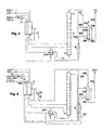
- FIG. 1 In the process of FIG. 1 is introduced via a line 1 compressed and purified feed air, which is under a pressure of about 3.5 bar.
- Air compressor and air purification - for example by means of a molecular sieve - are not shown in the drawing.
- the air is cooled in a main heat exchanger 2 to about dew point and fed via line 3 of a single column 4 at an intermediate point.
- the intermediate point is, for example, 5 to 20 theoretical plates or practically above the bottom of the column 4.
- the operating pressure at the bottom of the single column is 3.0 bar in the example.
- the top nitrogen 5 (the "nitrogen-rich fraction") from the single column 4 still contains 1 ppm to 1 ppb oxygen and is heated in a subcooler 6 and (line 7) further in the main heat exchanger 2 to about ambient temperature.
- the warm head nitrogen 8 is fed to a cycle compressor 9, which has, for example, two to three stages. Behind each stage of the cycle compressor is a subsequent or intermediate cooling to remove the heat of compression, of which, however, only the aftercooling 10 is shown behind the final stage in the schematic drawing.
- a first part 12 of the compressed to a pressure of 9.5 bar top nitrogen 11 is returned to the main heat exchanger 2, cooled there to several Kelvin above the column temperature and fed via line 13 to the liquefaction space of a condenser-evaporator 14.
- the nitrogen-rich liquid 15 formed in the process is subcooled in the subcooler 6 and fed via line 16 and throttle valve 17 to the top of the single column.
- a portion 18 of the nitrogen-rich liquid 16 may be withdrawn as liquid nitrogen product LIN.
- the liquid production in the example is about 0% of the amount of air.
- the liquid nitrogen is withdrawn from the single column, the head serves here as a flash gas between the throttle valve 17 and the liquid product removal 18.
- a second part 19 of the compressed in the cycle compressor 9 head nitrogen 11 is discharged as a gaseous nitrogen product under pressure (DGAN).
- DGAN gaseous nitrogen product under pressure
- a portion 20 of the pressurized nitrogen can be led out of an intermediate stage of the cycle compressor and recovered at a pressure between the operating pressure of the individual column 4 and the final pressure of the cycle compressor 9 as gaseous pressure nitrogen product (DGAN ').
- DGAN ' gaseous pressure nitrogen product
- the cycle compressor 9 serves as a product compressor at the same time.
- the condenser-evaporator 14 is in the example of FIG. 1 arranged directly in the bottom of the single column. On its evaporation side, the oxygen-enriched bottoms liquid of the single column 4 evaporates below its operating pressure to form a vapor having an oxygen content of about 80%. While a first part of the vapor generated in the condenser-evaporator 14 rises in the single column 4 ("first oxygen-enriched gas”), a second part 21 (“second oxygen-enriched gas”) is led to the cold end of the main heat exchanger 2. After warming to an intermediate temperature, this fraction flows via line 22 to a residual gas turbine 23 and is there to perform work from about 3 bar to about 1.5 bar relaxed.
- the work expanded oxygen-enriched gas 24 is completely warmed in the main heat exchanger 2 and discharged via line 25 as impure oxygen product UGOX. It can be used as a regeneration gas in the air purification, not shown, and / or as a gaseous by-product and / or released into the atmosphere.
- the turbine 23 can be regulated via a bypass 26. A small amount of liquid 27 is discharged continuously or intermittently as rinsing liquid from the evaporation space of the condenser-evaporator 14.
- the method according to FIG. 1 differs from the prior art according to US 4400188 by the way of cooling. This is accomplished here by working expansion of an oxygen-enriched gas 21 from the evaporation space of the condenser-evaporator 14. Although this measure causes a simplification of the apparatus, since only a single condenser-evaporator for the operation of the single column 4 is required, but this alone can not perform the desired simple variation of the liquid product content, as in the embodiments of the FIGS. 2 to 10 the case is.
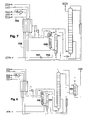
- the condenser-evaporator 214 is arranged in a separate container outside the single column 4. In the present case, this not only represents an apparatus-specific detail, but also enables the decoupling of the pressure in the evaporation space of the condenser-evaporator 214 from the operating pressure of the single column 4.
- the bottoms liquid (the "liquid oxygen-enriched fraction") 228 is here by means of a pump 229 brought a pressure of 4 to 8 bar and introduced under this increased pressure or optionally after slight throttling 230 via line 231 in the evaporation space of the condenser-evaporator 214.
- first oxygen-enriched gas a first portion
- second oxygen-enriched gas a second oxygen-enriched gas
- the procedure is reversed exactly the reverse.
- the condenser-evaporator 214 is then driven on the evaporation side with a pressure which is about 0.2 bar higher than the pressure at the bottom of the single column; the two pressures can be the same in extreme cases.
- the air compressor (not shown) and the cycle compressor 9 are preferably combined in the invention in a combination machine and provided with a common drive.
- the characteristic curve of the apparatus can be moved back and forth fully automatically between the abovementioned extreme operating cases and any intervening case, without the compaction machines (air compressor and cycle compressor) having to be readjusted. Only the residual gas turbines and the amount of gaseous product nitrogen need to be adjusted.
- FIGS. 3 to 8 show how the inventive method can be extended to a recovery of pure oxygen, high purity oxygen and / or high purity nitrogen.
- FIG. 3 corresponds largely FIG. 2 , The method and the device of FIG. 3 However, they additionally have a pure nitrogen column 335 with bottom evaporator 336. Head nitrogen 337 from the individual column 4 (operating pressure here: about 3 bar at the top) is at least partially condensed in the bottom evaporator 336 and fed via line 338 after throttling 339 to about 2.5 bar to the head of the pure nitrogen column 335. From the liquid flowing down in the column 335, more volatile components, in particular helium, neon and hydrogen are stripped off, which are withdrawn with a purge gas 340. In the swamp falls to highly pure nitrogen, which still contains about 0.1 ppm of impurities. It forms the liquid nitrogen product 318 to a first part.
- Head nitrogen 337 from the individual column 4 (operating pressure here: about 3 bar at the top) is at least partially condensed in the bottom evaporator 336 and fed via line 338 after throttling 339 to about 2.5 bar to the head of the pure nitrogen column 335.
- the remainder is withdrawn via line 342, forms the "nitrogen-rich fraction" and is fed to the cycle compressor 9.
- the nitrogen-rich liquid 316 produced in the condenser-evaporator 214 is partially fed to the top of the pure nitrogen column 335 via line 343. This amount of liquid nitrogen at the top of the pure nitrogen column 335 corresponds exactly to the amount of LIN product 318.
- the amount 388 is evaporated in the bottom evaporator 336 against itself.
- the cycle compressor 9 is different from FIG. 3 not directly fed with gas from the pure nitrogen column 335, but from the head gas 442 of the single column 4, which here forms the "nitrogen-rich fraction".
- the pressurized nitrogen product 19, 20 still contains volatile contaminants such as helium and neon.
- the overhead nitrogen which serves as an insert for the pure nitrogen column 335 and as a heating means for the bottom evaporator 435, is recirculated and branched off upstream of the condenser-evaporator 214 via line 437.
- the pure nitrogen column 335 can therefore be operated at a higher pressure than the single column, for example at 8 bar.
- a further gaseous compressed nitrogen product 444, 445 (UPDGAN) with particularly high purity can be obtained at the bottom of the pure nitrogen column 335. From the top of the pure nitrogen column 335, a residual fraction 446 is withdrawn and, for example, warmed together with the exhaust gas of the turbine 23 in the main heat exchanger 2.
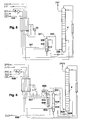
- the procedure and the plant of FIG. 5 serve to obtain additional oxygen of purity of 99.5 to 99.9999%, preferably 99.5 to 99.9%, which is argon-free (1 ppm argon or less).
- This is above the from the FIGS. 2 to 4 known capacitor evaporator 514 a mass transfer section arranged around the periphery of 30 to 60 theoretical or practical trays, which forms a pure oxygen column 546.
- the bottom liquid 528 of the single column 4 is not led directly to the condenser-evaporator 514, but fed to the head of the pure oxygen column 546. As it flows through this column, it continues to accumulate oxygen.
- the "liquid oxygen-enriched fraction" is formed here by the bottom liquid of the pure oxygen column 546.
- the top gas 532 of the pure oxygen column 546 of FIG. 5 forms to a first part of the "first oxygen-enriched gas” 533 and a second part of the "second oxygen-enriched gas” 521.
- the two fractions are supplied as in the embodiments described above, the single column or the work-performing expansion 23.
- a gaseous oxygen product GOX is withdrawn via the lines 547 and 548, which is purer than the first oxygen-enriched gas fraction 532.
- an additional column 649 which serves for the separation of less volatile components such as hydrocarbons, krypton and / or xenon from the gaseous bottom product 650 of the pure oxygen column 546. It is operated under the same pressure as the pure oxygen column 546 and has a top condenser 651 which is cooled with a part 652 of the sump liquid 628 of the single column 4 pressurized in the pump 629. Resulting steam 653 is added to the exhaust gas of the turbine 23. Via line 654 can also be made here a purge. The bottom liquid 655 of the additional column 649 is returned to the bottom of the pure oxygen column 546. At the top of the additional column 649, highly pure oxygen with a total content of 1 ppm of residual impurities accumulates. It is delivered to a first part 647, 648 as gaseous and to a second part 656 as liquid high purity product.
- FIG. 7 shows how the gaseous high purity oxygen can be discharged by means of internal compression under a pressure which is higher than the operating pressure of the additional column 649 and is for example about 8 bar.
- the entire high purity product is withdrawn via line 756 liquid, brought in a pump 757 to the elevated pressure. At least a portion 758 is vaporized under this pressure in the main heat exchanger 2 and discharged at 759 as a high purity pressure oxygen product.
- FIG. 8 are the pure nitrogen column 335 from FIG. 3 and the two columns 546 and 649 of FIG. 6 realized together, so that nitrogen and oxygen can be obtained simultaneously as high purity products UPDGAN, UPGOX.
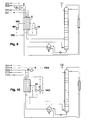
- a second turbine 961 in which a part 960 of the circulating nitrogen compressed in the cycle compressor is expanded to perform work. This is in FIG. 9 exemplified, the otherwise FIG. 2 equivalent. This part is discharged at an intermediate temperature from the main heat exchanger, which is equal to the inlet temperature of the first turbine 23 or higher or lower.
- the expanded nitrogen 962 is fed back into the circulation.
- the residual gas turbine 23 is coupled to a generator or to another braking device for dissipating mechanical energy, it drives in FIG. 10 directly to a booster 1063, which is upstream of the externally driven cycle compressor and this part of the compression work decreases, without consuming externally introduced energy.
- FIG. 10 is otherwise with FIG. 2 identical. Depending on the size of the system, it may be useful in each of the described embodiments to use such a turbine booster. In FIG. 10 In addition, the optional removal of a 1064 nitrogen product at the exit pressure of booster 1063 is shown.
- An essential aspect of the invention consists in a flexible operation of the plant with regard to the liquid product content.
- the diagram of FIG. 11 serves to illustrate these possibilities, the process of FIG. 2 to drive with different or varying product specifications, and indeed - in this one Example shown - at constant operation of the air compressor (9,400 Nm 3 / h at 3.4 bar outlet pressure) and the cycle compressor 9 (15,200 Nm 3 / h at 9.5 bar outlet pressure).
- the diagram shows the increase of the liquid product quantity (under curve) from just above zero (left) to 400 Nm 3 / h.
- the pressure in the condenser-evaporator and the turbine flow increase, while the oxygen concentration in the condenser and the amount of gaseous product nitrogen decrease.
- the operating pressure of the column within the column remains constant.
Landscapes
- Engineering & Computer Science (AREA)
- Physics & Mathematics (AREA)
- Mechanical Engineering (AREA)
- Thermal Sciences (AREA)
- General Engineering & Computer Science (AREA)
- Health & Medical Sciences (AREA)
- Emergency Medicine (AREA)
- Separation By Low-Temperature Treatments (AREA)
- Treating Waste Gases (AREA)
Claims (12)
- Procédé de production d'azote gazeux ou liquide à une proportion variable de produit liquide, par décomposition d'air à basse température dans un système à colonne de distillation qui présente une seule colonne (4), tandis que dans le procédé :- de l'air d'alimentation (1) est comprimé dans un compresseur d'air, est refroidi dans un échangeur de chaleur principal (2) et est apporté (3) à la colonne unique (4),- une fraction (5, 7, 8) riche en azote dont au moins une première partie étant comprimée dans un compresseur de circuit (9, 1063) est extraite du système de colonne de distillation,- la première partie (12, 13) de la fraction (5, 7, 8) riche en azote est apportée en aval du compresseur de circuit (1063, 9) à la chambre de liquéfaction d'un évaporateur-condenseur (214) pour y être condensée sous une pression supérieure à la pression de travail de la colonne unique (4), ce qui produit du liquide (15, 16) riche en azote,- au moins une partie d'une fraction liquide (228, 231) riche en oxygène provenant du système de colonne de distillation est évaporée dans la chambre d'évaporation de l'évaporateur-condenseur (214),- un premier gaz (234, 533) riche en oxygène est produit à partir de la vapeur (232) produite dans la chambre d'évaporation de l'évaporateur-condenseur (214), est introduit dans la colonne unique (4) et y est utilisé comme vapeur montante et- une deuxième partie (19, 20, 1064) de la fraction (5, 7, 8) riche en azote est extraite au moins une partie du temps sous la forme d'un produit gazeux d'azote,caractérisé en ce que- une partie (18) du liquide (15, 16) riche en azote est extraite de l'évaporateur-condenseur (214) au moins une partie du temps sous la forme d'un produit liquide,- la chambre d'évaporation de l'évaporateur-condenseur (214) est conduite au moins une partie du temps sous une pression supérieure à la pression de travail de la colonne unique (4) et- un deuxième gaz (221, 521) enrichi en oxygène est prélevé de l'une (546) des colonnes du système de distillation et/ou de la chambre d'évaporation de l'évaporateur-condenseur (214), est détendue (23) en produisant du travail et est chauffée dans l'échangeur de chaleur principal (2).
- Procédé selon la revendication 1, caractérisé en ce qu'un liquide (228, 528) enrichi en azote est extrait de la colonne unique (4) et est amené (229) à l'état liquide à une pression plus élevée, le deuxième gaz (232, 221, 521) enrichi en oxygène étant produit à partir du liquide (231) ainsi obtenu, enrichi en oxygène et placé sous pression plus élevée.
- Procédé selon la revendication 2, caractérisé en ce que le liquide (231) enrichi en oxygène forme en aval de l'augmentation de pression (229) la fraction liquide enrichie en oxygène qui est introduite dans la chambre d'évaporation de l'évaporateur-condenseur (214).
- Procédé selon la revendication 2, caractérisé en ce que le système de colonne de distillation présente une colonne (546) à oxygène pur, le liquide (231) enrichi en oxygène étant délivré en aval de l'augmentation de pression (229) dans la colonne (546) à oxygène pur et une fraction (547) riche en oxygène est extraite de la partie inférieure de la colonne (546) à oxygène pur, la fraction liquide enrichie en oxygène qui est apportée dans la chambre d'évaporation de l'évaporateur-condenseur (514) provenant de la partie inférieure de la colonne (546) à oxygène pur, la vapeur produite dans l'évaporateur-condenseur (514) étant introduite dans la partie inférieure de la colonne (546) à oxygène pur pour y être utilisée comme vapeur montante.
- Procédé selon la revendication 4, caractérisé en ce que le système de colonne de distillation présente une colonne supplémentaire (649) qui sert à éliminer les impuretés moins volatiles, la fraction (650) enrichie en oxygène provenant de la colonne (546) à oxygène pur étant introduite dans la colonne supplémentaire (649) et un produit d'oxygène pur (647, 656, 756, 758, 759) étant extrait de la partie supérieure de la colonne supplémentaire (649).
- Procédé selon la revendication 5, caractérisé en ce que la colonne supplémentaire (649) présente un condenseur de tête (651) dans lequel une deuxième fraction liquide (652) enrichie en oxygène provenant de la partie inférieure de la colonne unique (4) est évaporée au moins en partie.
- Procédé selon l'une des revendications précédentes, caractérisé en ce que la totalité du liquide renvoyé dans la colonne unique (4) et éventuellement dans la colonne (546) à oxygène pur est produit dans l'évaporateur-condenseur (14, 514).
- Procédé selon l'une des revendications précédentes, caractérisé en ce que le compresseur d'air et le compresseur de circuit (9) sont constitués d'une seule machine.
- Procédé selon l'une des revendications précédentes, caractérisé en ce qu'au moins une partie de l'énergie mécanique produite lors de la détente (23) avec production de travail du deuxième gaz (221, 521) enrichi en oxygène est utilisée pour comprimer (1063) la première partie et/ou la deuxième partie de la fraction (5, 7, 8) riche en azote.
- Procédé selon l'une des revendications précédentes, caractérisé en ce que le système de colonne de distillation présente une colonne (335) à azote pur, une fraction d'azote (338, 437) provenant de la partie supérieure de la colonne unique (4) étant délivrée à l'état liquide dans la colonne (335) à azote pur et un produit d'azote pur (318, 444, 445) étant extrait de la partie inférieure de la colonne (335) à azote pur.
- Procédé selon la revendication 10, caractérisé en ce que la colonne (335) à azote pur présente un évaporateur de pied (336, 435), la fraction d'azote (337, 437) étant prélevée à l'état gazeux de la colonne unique (4) et étant liquéfiée avant d'être délivrée (338, 339) dans l'évaporateur de pied (336, 435) de la colonne (335) à azote pur.
- Dispositif de production d'azote gazeux et d'azote liquide avec une fraction variable de produit liquide, par décomposition d'air à basse température dans un système de colonnes de distillation qui contiennent une colonne (4), et présentant :- un compresseur d'air,- un conduit d'alimentation (1, 3) qui relie le compresseur d'air à la colonne (4) par l'intermédiaire d'un échangeur de chaleur principal (2),- un compresseur de circuit (9, 1063) qui comprime la première partie d'une fraction (5, 7, 8) riche en azote provenant du système de colonnes de distillation,- un conduit de circuit (12, 13) qui relie la sortie du compresseur de circuit (1063, 9) à la chambre de liquéfaction d'un évaporateur-condenseur (14),- des moyens (228, 231) qui amènent une fraction liquide enrichie en oxygène provenant du système de colonnes de distillation à la chambre d'évaporation de l'évaporateur-condenseur (14),- des moyens de production d'un gaz (233, 533) enrichi en oxygène provenant de la vapeur (232) formée dans la chambre d'évaporation de l'évaporateur-condenseur (14) et pour l'introduire dans la colonne (4) et- un conduit de produit gazeux qui extrait une deuxième partie (19, 20, 1064) de la fraction (5, 7, 8) riche en azote comme produit gazeux d'azote,caractérisé par- un conduit de produit liquide (15, 16) relié à la chambre de liquéfaction de l'évaporateur-condenseur (14),- l'agencement de l'évaporateur-condenseur (14) à l'intérieur d'un récipient séparé de la colonne (4) et- une machine de détente (23) qui détend avec production de travail un deuxième gaz (221, 521) enrichi en oxygène provenant de l'une des colonnes (546) du système de distillation et/ou de la chambre d'évaporation de l'évaporateur-condenseur (14).
Applications Claiming Priority (4)
| Application Number | Priority Date | Filing Date | Title |
|---|---|---|---|
| DE10013075 | 2000-03-17 | ||
| DE10013075A DE10013075A1 (de) | 2000-03-17 | 2000-03-17 | Verfahren zur Gewinnung von gasförmigem und flüssigem Stickstoff mit variablem Anteil des Flüssigprodukts |
| EP01105924 | 2001-03-09 | ||
| EP01105924 | 2001-03-09 |
Publications (2)
| Publication Number | Publication Date |
|---|---|
| EP1134525A1 EP1134525A1 (fr) | 2001-09-19 |
| EP1134525B1 true EP1134525B1 (fr) | 2010-09-15 |
Family
ID=7635136
Family Applications (1)
| Application Number | Title | Priority Date | Filing Date |
|---|---|---|---|
| EP01106637A Expired - Lifetime EP1134525B1 (fr) | 2000-03-17 | 2001-03-16 | Procédé de production d'azote liquide et gazeux avec une quantité variable de liquide |
Country Status (4)
| Country | Link |
|---|---|
| US (1) | US6477860B2 (fr) |
| EP (1) | EP1134525B1 (fr) |
| AT (1) | ATE481607T1 (fr) |
| DE (2) | DE10013075A1 (fr) |
Cited By (1)
| Publication number | Priority date | Publication date | Assignee | Title |
|---|---|---|---|---|
| DE202015004181U1 (de) | 2015-06-12 | 2015-07-09 | Linde Aktiengesellschaft | Luftzerlegungsanlage und Steuereinrichtung für Luftzerlegungsanlage |
Families Citing this family (30)
| Publication number | Priority date | Publication date | Assignee | Title |
|---|---|---|---|---|
| US7284395B2 (en) * | 2004-09-02 | 2007-10-23 | Praxair Technology, Inc. | Cryogenic air separation plant with reduced liquid drain loss |
| US20060260327A1 (en) * | 2005-05-18 | 2006-11-23 | Shoji Kanamori | Apparatus and method for rapidly freezing small objects |
| DE102007024168A1 (de) * | 2007-05-24 | 2008-11-27 | Linde Ag | Verfahren und Vorrichtung zur Tieftemperatur-Luftzerlegung |
| DE102007031759A1 (de) | 2007-07-07 | 2009-01-08 | Linde Ag | Verfahren und Vorrichtung zur Erzeugung von gasförmigem Druckprodukt durch Tieftemperaturzerlegung von Luft |
| DE102007031765A1 (de) | 2007-07-07 | 2009-01-08 | Linde Ag | Verfahren zur Tieftemperaturzerlegung von Luft |
| DE102007051184A1 (de) * | 2007-10-25 | 2009-04-30 | Linde Aktiengesellschaft | Verfahren und Vorrichtung zur Tieftemperatur-Luftzerlegung |
| DE102007051183A1 (de) * | 2007-10-25 | 2009-04-30 | Linde Aktiengesellschaft | Verfahren zur Tieftemperatur-Luftzerlegung |
| DE102009034979A1 (de) | 2009-04-28 | 2010-11-04 | Linde Aktiengesellschaft | Verfahren und Vorrichtung zur Erzeugung von gasförmigem Drucksauerstoff |
| EP2312248A1 (fr) | 2009-10-07 | 2011-04-20 | Linde Aktiengesellschaft | Procédé et dispositif de production d'oxygène sous pression et de crypton/xénon |
| DE102010052544A1 (de) | 2010-11-25 | 2012-05-31 | Linde Ag | Verfahren zur Gewinnung eines gasförmigen Druckprodukts durch Tieftemperaturzerlegung von Luft |
| DE102010052545A1 (de) | 2010-11-25 | 2012-05-31 | Linde Aktiengesellschaft | Verfahren und Vorrichtung zur Gewinnung eines gasförmigen Druckprodukts durch Tieftemperaturzerlegung von Luft |
| EP2520886A1 (fr) | 2011-05-05 | 2012-11-07 | Linde AG | Procédé et dispositif de production d'un produit comprimé à oxygène gazeux par décomposition à basse température d'air |
| DE102011112909A1 (de) | 2011-09-08 | 2013-03-14 | Linde Aktiengesellschaft | Verfahren und Vorrichtung zur Gewinnung von Stahl |
| EP2600090B1 (fr) | 2011-12-01 | 2014-07-16 | Linde Aktiengesellschaft | Procédé et dispositif destinés à la production d'oxygène sous pression par décomposition à basse température de l'air |
| DE102011121314A1 (de) | 2011-12-16 | 2013-06-20 | Linde Aktiengesellschaft | Verfahren zur Erzeugung eines gasförmigen Sauerstoff-Druckprodukts durch Tieftemperaturzerlegung von Luft |
| DE102012017488A1 (de) | 2012-09-04 | 2014-03-06 | Linde Aktiengesellschaft | Verfahren zur Erstellung einer Luftzerlegungsanlage, Luftzerlegungsanlage und zugehöriges Betriebsverfahren |
| WO2014154339A2 (fr) | 2013-03-26 | 2014-10-02 | Linde Aktiengesellschaft | Procédé de séparation d'air et installation de séparation d'air |
| EP2784420A1 (fr) | 2013-03-26 | 2014-10-01 | Linde Aktiengesellschaft | Procédé de séparation de l'air et installation de séparation de l'air |
| WO2014154361A2 (fr) * | 2013-03-28 | 2014-10-02 | Linde Aktiengesellschaft | Procédé et dispositif permettant de produire avec une consommation d'énergie variable de l'oxygène sous pression sous forme gazeuse |
| EP2801777A1 (fr) | 2013-05-08 | 2014-11-12 | Linde Aktiengesellschaft | Installation de décomposition de l'air dotée d'un entraînement de compresseur principal |
| DE102013017590A1 (de) | 2013-10-22 | 2014-01-02 | Linde Aktiengesellschaft | Verfahren zur Gewinnung eines Krypton und Xenon enthaltenden Fluids und hierfür eingerichtete Luftzerlegungsanlage |
| EP2963367A1 (fr) | 2014-07-05 | 2016-01-06 | Linde Aktiengesellschaft | Procédé et dispositif cryogéniques de séparation d'air avec consommation d'énergie variable |
| EP2963371B1 (fr) | 2014-07-05 | 2018-05-02 | Linde Aktiengesellschaft | Procede et dispositif de production d'un produit de gaz sous pression par decomposition a basse temperature d'air |
| PL2963370T3 (pl) | 2014-07-05 | 2018-11-30 | Linde Aktiengesellschaft | Sposób i urządzenie do kriogenicznego rozdziału powietrza |
| PL2963369T3 (pl) | 2014-07-05 | 2018-10-31 | Linde Aktiengesellschaft | Sposób i urządzenie do niskotemperaturowej separacji powietrza |
| EP3870917B1 (fr) * | 2018-10-23 | 2024-03-27 | Linde GmbH | Procédé et installation de séparation cryogénique d'air |
| WO2021204418A1 (fr) * | 2020-04-09 | 2021-10-14 | Linde Gmbh | Procédé de production d'un produit d'azote gazeux et liquide au moyen d'une séparation à basse température de l'air, et système de séparation d'air |
| CN114165988B (zh) * | 2021-11-22 | 2023-01-31 | 四川空分设备(集团)有限责任公司 | 低压氮制取装置及方法 |
| CN114183997B (zh) * | 2021-11-22 | 2023-03-24 | 四川空分设备(集团)有限责任公司 | 一种制取低压氮气的装置及方法 |
| JP7379764B1 (ja) * | 2022-08-09 | 2023-11-15 | レール・リキード-ソシエテ・アノニム・プール・レテュード・エ・レクスプロワタシオン・デ・プロセデ・ジョルジュ・クロード | 空気分離装置および空気分離方法 |
Family Cites Families (11)
| Publication number | Priority date | Publication date | Assignee | Title |
|---|---|---|---|---|
| GB1392294A (en) * | 1971-06-28 | 1975-04-30 | British Oxygen Co Ltd | Air separation |
| US4400188A (en) * | 1981-10-27 | 1983-08-23 | Air Products And Chemicals, Inc. | Nitrogen generator cycle |
| US4834785A (en) * | 1988-06-20 | 1989-05-30 | Air Products And Chemicals, Inc. | Cryogenic nitrogen generator with nitrogen expander |
| FR2689224B1 (fr) * | 1992-03-24 | 1994-05-06 | Lair Liquide | Procede et installation de production d'azote sous haute pression et d'oxygene. |
| US5275004A (en) * | 1992-07-21 | 1994-01-04 | Air Products And Chemicals, Inc. | Consolidated heat exchanger air separation process |
| DE19543395A1 (de) * | 1995-11-21 | 1997-05-22 | Linde Ag | Doppelsäulenverfahren und -vorrichtung zur Tieftemperaturzerlegung von Luft |
| FR2757282B1 (fr) * | 1996-12-12 | 2006-06-23 | Air Liquide | Procede et installation de fourniture d'un debit variable d'un gaz de l'air |
| FR2767317B1 (fr) | 1997-08-14 | 1999-09-10 | Air Liquide | Procede de conversion d'un debit contenant des hydrocarbures par oxydation partielle |
| US5966967A (en) * | 1998-01-22 | 1999-10-19 | Air Products And Chemicals, Inc. | Efficient process to produce oxygen |
| GB9806293D0 (en) * | 1998-03-24 | 1998-05-20 | Boc Group Plc | Separation of air |
| DE10013073A1 (de) * | 2000-03-17 | 2000-10-19 | Linde Ag | Verfahren und Vorrichtung zur Tieftemperaturzerlegung von Luft |
-
2000
- 2000-03-17 DE DE10013075A patent/DE10013075A1/de not_active Withdrawn
-
2001
- 2001-03-16 EP EP01106637A patent/EP1134525B1/fr not_active Expired - Lifetime
- 2001-03-16 AT AT01106637T patent/ATE481607T1/de active
- 2001-03-16 DE DE50115625T patent/DE50115625D1/de not_active Expired - Lifetime
- 2001-03-19 US US09/810,340 patent/US6477860B2/en not_active Expired - Fee Related
Cited By (1)
| Publication number | Priority date | Publication date | Assignee | Title |
|---|---|---|---|---|
| DE202015004181U1 (de) | 2015-06-12 | 2015-07-09 | Linde Aktiengesellschaft | Luftzerlegungsanlage und Steuereinrichtung für Luftzerlegungsanlage |
Also Published As
| Publication number | Publication date |
|---|---|
| DE50115625D1 (de) | 2010-10-28 |
| US6477860B2 (en) | 2002-11-12 |
| EP1134525A1 (fr) | 2001-09-19 |
| ATE481607T1 (de) | 2010-10-15 |
| DE10013075A1 (de) | 2001-09-20 |
| US20010054298A1 (en) | 2001-12-27 |
Similar Documents
| Publication | Publication Date | Title |
|---|---|---|
| EP1134525A1 (fr) | Procédé de production d'azote liquide et gazeux avec une quantité variable de liquide | |
| DE69404106T2 (de) | Lufttrennungsschemas für die Koproduktion von Sauerstoff und Stickstoff als Gas- und/oder Flüssigprodukt | |
| EP1308680B1 (fr) | Procédé et dispositif de production de krypton et/ou xénon par distillation cryogénique de l'air | |
| EP1067345B1 (fr) | Procédé et dispositif pour la séparation cryogénique des constituants de l'air | |
| DE69509841T2 (de) | Verfahren und Vorrichtung zur Herstellung von Sauerstoff | |
| DE69413918T2 (de) | Tieftemperaturzerlegung von Luft | |
| DE69214693T2 (de) | Verfahren zur Herstellung von gasförmigem Sauerstoff unter Druck | |
| EP2235460B1 (fr) | Procédé et installation pour la séparation cryogénique d'air | |
| EP3290843A2 (fr) | Procédé et dispositif destiné à fabriquer de l'azote pressurisé et liquide par décomposition à basse température de l'air | |
| DE102010052545A1 (de) | Verfahren und Vorrichtung zur Gewinnung eines gasförmigen Druckprodukts durch Tieftemperaturzerlegung von Luft | |
| DE102007014643A1 (de) | Verfahren und Vorrichtung zur Erzeugung von gasförmigem Druckprodukt durch Tieftemperaturzerlegung von Luft | |
| DE10139727A1 (de) | Verfahren und Vorrichtung zur Gewinnung eines Druckprodukts durch Tieftemperaturzerlegung von Luft | |
| EP2236964A1 (fr) | Procédé et dispositif de séparation de l'air à basse température | |
| EP1074805B1 (fr) | Procédé et dispositif pour la production d'oxygène sous pression | |
| DE19609490A1 (de) | Verfahren und Vorrichtung zur Tieftemperaturzerlegung von Luft | |
| WO2014146779A2 (fr) | Procédé et dispositif de production d'azote gazeux sous pression | |
| EP2053331A1 (fr) | Procédé et dispositif de séparation de l'air à basse température | |
| WO2014154361A2 (fr) | Procédé et dispositif permettant de produire avec une consommation d'énergie variable de l'oxygène sous pression sous forme gazeuse | |
| DE10103968A1 (de) | Drei-Säulen-System zur Tieftemperaturzerlegung von Luft | |
| DE19537913A1 (de) | Dreifachsäulenverfahren zur Tieftemperaturzerlegung von Luft | |
| EP3980705A1 (fr) | Procédé et installation de décomposition d'air à basse température | |
| DE102007042462A1 (de) | Verfahren und Vorrichtung zur Tieftemperaturzerlegung von Luft | |
| EP2551619A1 (fr) | Procédé et dispositif destinés à l'obtention d'oxygène pressurisé et d'azote pressurisé par la décomposition à basse température de l'air | |
| DE102017010001A1 (de) | Verfahren und Anlage zur Tieftemperaturzerlegung von Luft | |
| DE19933558C5 (de) | Dreisäulenverfahren und -vorrichtung zur Tieftemperaturzerlegung von Luft |
Legal Events
| Date | Code | Title | Description |
|---|---|---|---|
| PUAI | Public reference made under article 153(3) epc to a published international application that has entered the european phase |
Free format text: ORIGINAL CODE: 0009012 |
|
| AK | Designated contracting states |
Kind code of ref document: A1 Designated state(s): AT BE CH CY DE DK ES FI FR GB GR IE IT LI LU MC NL PT SE TR |
|
| AX | Request for extension of the european patent |
Free format text: AL;LT;LV;MK;RO;SI |
|
| 17P | Request for examination filed |
Effective date: 20020316 |
|
| AKX | Designation fees paid |
Free format text: AT BE CH CY DE DK ES FI FR GB GR IE IT LI LU MC NL PT SE TR |
|
| 17Q | First examination report despatched |
Effective date: 20050111 |
|
| RAP1 | Party data changed (applicant data changed or rights of an application transferred) |
Owner name: LINDE AKTIENGESELLSCHAFT |
|
| RAP1 | Party data changed (applicant data changed or rights of an application transferred) |
Owner name: LINDE AG |
|
| GRAP | Despatch of communication of intention to grant a patent |
Free format text: ORIGINAL CODE: EPIDOSNIGR1 |
|
| GRAS | Grant fee paid |
Free format text: ORIGINAL CODE: EPIDOSNIGR3 |
|
| GRAA | (expected) grant |
Free format text: ORIGINAL CODE: 0009210 |
|
| RIN1 | Information on inventor provided before grant (corrected) |
Inventor name: KUNZ, CHRISTIAN, DIPL.-ING. Inventor name: ROTTMANN, DIETRICH, DIPL.-ING. |
|
| AK | Designated contracting states |
Kind code of ref document: B1 Designated state(s): AT BE CH CY DE DK ES FI FR GB GR IE IT LI LU MC NL PT SE TR |
|
| REG | Reference to a national code |
Ref country code: GB Ref legal event code: FG4D Free format text: NOT ENGLISH Ref country code: CH Ref legal event code: EP |
|
| REG | Reference to a national code |
Ref country code: IE Ref legal event code: FG4D Free format text: LANGUAGE OF EP DOCUMENT: GERMAN |
|
| REF | Corresponds to: |
Ref document number: 50115625 Country of ref document: DE Date of ref document: 20101028 Kind code of ref document: P |
|
| REG | Reference to a national code |
Ref country code: NL Ref legal event code: VDEP Effective date: 20100915 |
|
| PG25 | Lapsed in a contracting state [announced via postgrant information from national office to epo] |
Ref country code: FI Free format text: LAPSE BECAUSE OF FAILURE TO SUBMIT A TRANSLATION OF THE DESCRIPTION OR TO PAY THE FEE WITHIN THE PRESCRIBED TIME-LIMIT Effective date: 20100915 |
|
| PG25 | Lapsed in a contracting state [announced via postgrant information from national office to epo] |
Ref country code: CY Free format text: LAPSE BECAUSE OF FAILURE TO SUBMIT A TRANSLATION OF THE DESCRIPTION OR TO PAY THE FEE WITHIN THE PRESCRIBED TIME-LIMIT Effective date: 20100915 |
|
| PG25 | Lapsed in a contracting state [announced via postgrant information from national office to epo] |
Ref country code: GR Free format text: LAPSE BECAUSE OF FAILURE TO SUBMIT A TRANSLATION OF THE DESCRIPTION OR TO PAY THE FEE WITHIN THE PRESCRIBED TIME-LIMIT Effective date: 20101216 Ref country code: SE Free format text: LAPSE BECAUSE OF FAILURE TO SUBMIT A TRANSLATION OF THE DESCRIPTION OR TO PAY THE FEE WITHIN THE PRESCRIBED TIME-LIMIT Effective date: 20100915 |
|
| REG | Reference to a national code |
Ref country code: IE Ref legal event code: FD4D |
|
| PG25 | Lapsed in a contracting state [announced via postgrant information from national office to epo] |
Ref country code: IE Free format text: LAPSE BECAUSE OF FAILURE TO SUBMIT A TRANSLATION OF THE DESCRIPTION OR TO PAY THE FEE WITHIN THE PRESCRIBED TIME-LIMIT Effective date: 20100915 |
|
| PG25 | Lapsed in a contracting state [announced via postgrant information from national office to epo] |
Ref country code: NL Free format text: LAPSE BECAUSE OF FAILURE TO SUBMIT A TRANSLATION OF THE DESCRIPTION OR TO PAY THE FEE WITHIN THE PRESCRIBED TIME-LIMIT Effective date: 20100915 Ref country code: IT Free format text: LAPSE BECAUSE OF FAILURE TO SUBMIT A TRANSLATION OF THE DESCRIPTION OR TO PAY THE FEE WITHIN THE PRESCRIBED TIME-LIMIT Effective date: 20100915 Ref country code: PT Free format text: LAPSE BECAUSE OF FAILURE TO SUBMIT A TRANSLATION OF THE DESCRIPTION OR TO PAY THE FEE WITHIN THE PRESCRIBED TIME-LIMIT Effective date: 20110117 |
|
| PG25 | Lapsed in a contracting state [announced via postgrant information from national office to epo] |
Ref country code: ES Free format text: LAPSE BECAUSE OF FAILURE TO SUBMIT A TRANSLATION OF THE DESCRIPTION OR TO PAY THE FEE WITHIN THE PRESCRIBED TIME-LIMIT Effective date: 20101226 |
|
| PLBE | No opposition filed within time limit |
Free format text: ORIGINAL CODE: 0009261 |
|
| STAA | Information on the status of an ep patent application or granted ep patent |
Free format text: STATUS: NO OPPOSITION FILED WITHIN TIME LIMIT |
|
| PGFP | Annual fee paid to national office [announced via postgrant information from national office to epo] |
Ref country code: GB Payment date: 20110316 Year of fee payment: 11 Ref country code: DE Payment date: 20110309 Year of fee payment: 11 |
|
| 26N | No opposition filed |
Effective date: 20110616 |
|
| PG25 | Lapsed in a contracting state [announced via postgrant information from national office to epo] |
Ref country code: DK Free format text: LAPSE BECAUSE OF FAILURE TO SUBMIT A TRANSLATION OF THE DESCRIPTION OR TO PAY THE FEE WITHIN THE PRESCRIBED TIME-LIMIT Effective date: 20100915 |
|
| BERE | Be: lapsed |
Owner name: LINDE A.G. Effective date: 20110331 |
|
| REG | Reference to a national code |
Ref country code: DE Ref legal event code: R097 Ref document number: 50115625 Country of ref document: DE Effective date: 20110616 |
|
| PG25 | Lapsed in a contracting state [announced via postgrant information from national office to epo] |
Ref country code: MC Free format text: LAPSE BECAUSE OF NON-PAYMENT OF DUE FEES Effective date: 20110331 |
|
| REG | Reference to a national code |
Ref country code: CH Ref legal event code: PL |
|
| PG25 | Lapsed in a contracting state [announced via postgrant information from national office to epo] |
Ref country code: BE Free format text: LAPSE BECAUSE OF NON-PAYMENT OF DUE FEES Effective date: 20110331 |
|
| PG25 | Lapsed in a contracting state [announced via postgrant information from national office to epo] |
Ref country code: LI Free format text: LAPSE BECAUSE OF NON-PAYMENT OF DUE FEES Effective date: 20110331 Ref country code: CH Free format text: LAPSE BECAUSE OF NON-PAYMENT OF DUE FEES Effective date: 20110331 |
|
| PGFP | Annual fee paid to national office [announced via postgrant information from national office to epo] |
Ref country code: FR Payment date: 20120319 Year of fee payment: 12 |
|
| GBPC | Gb: european patent ceased through non-payment of renewal fee |
Effective date: 20120316 |
|
| REG | Reference to a national code |
Ref country code: AT Ref legal event code: MM01 Ref document number: 481607 Country of ref document: AT Kind code of ref document: T Effective date: 20110316 |
|
| PG25 | Lapsed in a contracting state [announced via postgrant information from national office to epo] |
Ref country code: AT Free format text: LAPSE BECAUSE OF NON-PAYMENT OF DUE FEES Effective date: 20110316 Ref country code: GB Free format text: LAPSE BECAUSE OF NON-PAYMENT OF DUE FEES Effective date: 20120316 |
|
| REG | Reference to a national code |
Ref country code: DE Ref legal event code: R119 Ref document number: 50115625 Country of ref document: DE Effective date: 20121002 |
|
| PG25 | Lapsed in a contracting state [announced via postgrant information from national office to epo] |
Ref country code: LU Free format text: LAPSE BECAUSE OF NON-PAYMENT OF DUE FEES Effective date: 20110316 |
|
| PG25 | Lapsed in a contracting state [announced via postgrant information from national office to epo] |
Ref country code: TR Free format text: LAPSE BECAUSE OF FAILURE TO SUBMIT A TRANSLATION OF THE DESCRIPTION OR TO PAY THE FEE WITHIN THE PRESCRIBED TIME-LIMIT Effective date: 20100915 |
|
| REG | Reference to a national code |
Ref country code: FR Ref legal event code: ST Effective date: 20131129 |
|
| PG25 | Lapsed in a contracting state [announced via postgrant information from national office to epo] |
Ref country code: FR Free format text: LAPSE BECAUSE OF NON-PAYMENT OF DUE FEES Effective date: 20130402 |
|
| PG25 | Lapsed in a contracting state [announced via postgrant information from national office to epo] |
Ref country code: DE Free format text: LAPSE BECAUSE OF NON-PAYMENT OF DUE FEES Effective date: 20121002 |