EP1134531A1 - Scheibenrolle für Rollenherdöfen - Google Patents
Scheibenrolle für Rollenherdöfen Download PDFInfo
- Publication number
- EP1134531A1 EP1134531A1 EP01105199A EP01105199A EP1134531A1 EP 1134531 A1 EP1134531 A1 EP 1134531A1 EP 01105199 A EP01105199 A EP 01105199A EP 01105199 A EP01105199 A EP 01105199A EP 1134531 A1 EP1134531 A1 EP 1134531A1
- Authority
- EP
- European Patent Office
- Prior art keywords
- support
- support elements
- disc
- elements
- rings
- Prior art date
- Legal status (The legal status is an assumption and is not a legal conclusion. Google has not performed a legal analysis and makes no representation as to the accuracy of the status listed.)
- Granted
Links
- 238000010438 heat treatment Methods 0.000 claims description 4
- 238000009413 insulation Methods 0.000 claims description 4
- 239000000463 material Substances 0.000 claims description 3
- 238000013459 approach Methods 0.000 description 2
- 239000002826 coolant Substances 0.000 description 1
- 239000011810 insulating material Substances 0.000 description 1
- 238000012986 modification Methods 0.000 description 1
- 230000004048 modification Effects 0.000 description 1
Images
Classifications
-
- F—MECHANICAL ENGINEERING; LIGHTING; HEATING; WEAPONS; BLASTING
- F27—FURNACES; KILNS; OVENS; RETORTS
- F27D—DETAILS OR ACCESSORIES OF FURNACES, KILNS, OVENS OR RETORTS, IN SO FAR AS THEY ARE OF KINDS OCCURRING IN MORE THAN ONE KIND OF FURNACE
- F27D3/00—Charging; Discharging; Manipulation of charge
- F27D3/02—Skids or tracks for heavy objects
- F27D3/026—Skids or tracks for heavy objects transport or conveyor rolls for furnaces; roller rails
-
- C—CHEMISTRY; METALLURGY
- C21—METALLURGY OF IRON
- C21D—MODIFYING THE PHYSICAL STRUCTURE OF FERROUS METALS; GENERAL DEVICES FOR HEAT TREATMENT OF FERROUS OR NON-FERROUS METALS OR ALLOYS; MAKING METAL MALLEABLE, e.g. BY DECARBURISATION OR TEMPERING
- C21D9/00—Heat treatment, e.g. annealing, hardening, quenching or tempering, adapted for particular articles; Furnaces therefor
- C21D9/0006—Details, accessories not peculiar to any of the following furnaces
- C21D9/0012—Rolls; Roll arrangements
-
- F—MECHANICAL ENGINEERING; LIGHTING; HEATING; WEAPONS; BLASTING
- F16—ENGINEERING ELEMENTS AND UNITS; GENERAL MEASURES FOR PRODUCING AND MAINTAINING EFFECTIVE FUNCTIONING OF MACHINES OR INSTALLATIONS; THERMAL INSULATION IN GENERAL
- F16C—SHAFTS; FLEXIBLE SHAFTS; ELEMENTS OR CRANKSHAFT MECHANISMS; ROTARY BODIES OTHER THAN GEARING ELEMENTS; BEARINGS
- F16C13/00—Rolls, drums, discs, or the like; Bearings or mountings therefor
Definitions
- the invention relates to a disc roller for roller hearth furnaces for heating Heat material according to the preamble of claim 1.
- Such a disc roller is known from EP B1-O44312.
- the Support rings connected to the support elements by bolts.
- the temperature behavior such disc rollers is good because there is no direct heat flow between the support ring and the support tube occurs.
- the support tube rotates and takes the disc roller with it. This will loaded by the heating material on one side during the rotary movement. there it comes in the support ring, especially in the area of the connection with the Supporting elements, for voltage peaks. The result is cracks, so that after the support elements and the support rings can be replaced in a relatively short time have to.
- the object of the invention is accordingly, a disc roller improve the type mentioned so that the durability improves and the disassembly of the support ring is simplified.
- the support ring is connected to the support elements by means of a positive connection connected. This is designed so that the support ring during the Rotation can roll on the support elements.
- the adhesion migrates between the door ring and the support elements during the Rotation between two angles, approximately between 90 ° and 30 ° in Direction of rotation seen, against the direction of rotation. This will Voltage peaks avoided or reduced. Also the other problems that in the prior art due to the two-sided clamped support elements are avoided. In particular, the disassembly of the support rings much simplified.
- a further development of the disc roller according to the invention is that
- the circumference of the support elements has a wavy circumferential profile, wherein the support ring is designed accordingly.
- the support elements disc-shaped and have a cylindrical approach in which at least a recess is provided which extends in the axial direction and into which Fastening element is used, which is partially welded to the support tube is. This simplifies the assembly and disassembly of the support elements, because the weld to be separated between the fastener and Support tube is relatively short. There are usually two fasteners per Sufficient support element.
- the end faces of the support ring preferably close with the end faces the support elements from essentially flush to a flush concern Allow insulation.
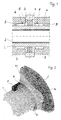
- the disc roller according to the invention comprises a support tube 1, in the coaxially Inner tube 2 is arranged, through which a coolant flows.
- a support tube 1 On the Support tube 1 is arranged a plurality of disc rollers, of which only one is shown and which consists essentially of a support ring 3 and two Support elements 5 exist.
- the longitudinal sections between the support rings are surrounded by insulation 4.
- Each support ring 3 sits on two side support elements 5, which are disc-shaped are and have a cylindrical extension 6.
- Fig. 2 it is shown that in the cylindrical extension 6 at least one Recess 8 is provided, which extends in the axial direction and in the Fastening element 9 is used.
- the fastener 9 is longer than the recess 8 and projects in the axial direction over the cylindrical extension 6 out. This protruding part is welded to the support tube 1. Since the The weld is relatively short, the disassembly of the support elements is relative simple.
- the support elements 5 point in the circumferential direction fully rounded ridges10 that are spaced apart the scope are distributed.
- the outward elevations 10 engage in correspondingly shaped recesses 11 in the support ring 3.
- the support ring 3 rolls forcefully onto the Support elements 5 from.
- the adhesion travels during the rotation on the Circumference in the direction of rotation and counter to this, in one Angular range from about 90 ° to 30 ° seen in the direction of rotation. This will Voltage peaks avoided or reduced.
- the end faces of the support rings 3 are essentially flush with the End faces of the support elements 5 to ensure that the insulation 4 lies flush to enable.
- connection of the support elements with the support tube for example by a tongue and groove system.
Landscapes
- Engineering & Computer Science (AREA)
- Chemical & Material Sciences (AREA)
- Mechanical Engineering (AREA)
- General Engineering & Computer Science (AREA)
- Metallurgy (AREA)
- Thermal Sciences (AREA)
- Crystallography & Structural Chemistry (AREA)
- Materials Engineering (AREA)
- Physics & Mathematics (AREA)
- Organic Chemistry (AREA)
- Rollers For Roller Conveyors For Transfer (AREA)
- Tunnel Furnaces (AREA)
- Rolls And Other Rotary Bodies (AREA)
- General Induction Heating (AREA)
- Heat Treatment Of Strip Materials And Filament Materials (AREA)
- Heat Treatments In General, Especially Conveying And Cooling (AREA)
Abstract
Description
- Fig. 1
- einen axialen Teilschnitt durch eine erfindungsgemäße Scheibenrolle;
- Fig. 2
- eine perspektivische Seitenansicht der Scheibenrolle nach Fig. 1.
Claims (4)
- Scheibenrolle für Rollenherdöfen zum Erwärmen von Wärmgut, mitwobei mindestens ein Tragelement (5) pro Scheibenrolle drehfest mit dem Tragrohr (1) verbunden ist,einem drehbaren intern gekühlten Tragrohr (1),einer Mehrzahl von in axialem Abstand zueinander auf dem Tragrohr angeordneten Tragringen (3), die auf zwei seitlichen Tragelementen (5) aufsitzen und mit diesen lösbar verbunden sind,einer das Tragrohr( 1) neben den Tragringen (3) umgebende Isolierung (4),
dadurch gekennzeichnet, daß die Tragelemente (5) in Umfangsrichtung abgerundete Erhöhungen (10) aufweisen, die mit Abstand zueinander auf dem Umfang verteilt sind und die in entsprechend geformte Vertiefungen (11) in den Tragringen (3) eingreifen. - Scheibenrolle nach Anspruch 1,
dadurch gekennzeichnet, daß der Umfang der Tragelemente (5) ein wellenförmiges Profil aufweist, wobei die Tragringe (3) korrespondierend ausgebildet sind. - Scheibenrolle nach Anspruch 1 oder 2,
dadurch gekennzeichnet, daß die Tragelemente (5) scheibenförmig sind und einen zylindrischen Ansatz (6) aufweisen, in dem mindestens eine Ausnehmung (8) vorgesehen ist, die sich in Achsrichtung erstreckt und in die formschlüssig ein Befestigungselement (9) eingesetzt ist, welches teilweise mit dem Tragrohr (1) verschweißt ist. - Scheibenrolle nach einem der Ansprüche 1 bis 3,
dadurch gekennzeichnet, daß die Stirnflächen der Tragringe (3) mit den Stirnflächen der Tragelemente (5) im wesentlichen bündig abschließen.
Applications Claiming Priority (2)
| Application Number | Priority Date | Filing Date | Title |
|---|---|---|---|
| DE10012940A DE10012940A1 (de) | 2000-03-16 | 2000-03-16 | Scheibenrolle für Rollenherdöfen |
| DE10012940 | 2000-03-16 |
Publications (2)
| Publication Number | Publication Date |
|---|---|
| EP1134531A1 true EP1134531A1 (de) | 2001-09-19 |
| EP1134531B1 EP1134531B1 (de) | 2006-06-07 |
Family
ID=7635034
Family Applications (1)
| Application Number | Title | Priority Date | Filing Date |
|---|---|---|---|
| EP01105199A Expired - Lifetime EP1134531B1 (de) | 2000-03-16 | 2001-03-03 | Scheibenrolle für Rollenherdöfen |
Country Status (5)
| Country | Link |
|---|---|
| EP (1) | EP1134531B1 (de) |
| CN (1) | CN1183370C (de) |
| AT (1) | ATE329219T1 (de) |
| DE (2) | DE10012940A1 (de) |
| ES (1) | ES2266035T3 (de) |
Cited By (3)
| Publication number | Priority date | Publication date | Assignee | Title |
|---|---|---|---|---|
| EP1189004A1 (de) * | 2000-09-13 | 2002-03-20 | SMS Demag AG | Wasserkühlbare Ofenrolle |
| US10088237B2 (en) | 2014-11-28 | 2018-10-02 | Sms Group Gmbh | Uncooled furnace roll and method for producing an uncooled furnace roll |
| WO2020083673A1 (de) * | 2018-10-25 | 2020-04-30 | Loi Thermprocess Gmbh | Abkühl-einrichtung zum abkühlen von platten- oder bandförmigem blech aus metall sowie abkühlverfahren |
Families Citing this family (2)
| Publication number | Priority date | Publication date | Assignee | Title |
|---|---|---|---|---|
| FR2884306B1 (fr) * | 2005-04-07 | 2007-05-11 | Stein Heurtey | Rouleau refroidi pour la manutention de produits siderurgiques |
| KR101448699B1 (ko) * | 2014-08-11 | 2014-10-10 | 대한동방 주식회사 | 캐로셀롤이 설치된 열처리로의 실링장치 및 그것이 설치된 열처리로 |
Citations (7)
| Publication number | Priority date | Publication date | Assignee | Title |
|---|---|---|---|---|
| GB468482A (en) * | 1935-10-17 | 1937-07-06 | Stowe Woodward Inc | Improvements in or relating to rolls |
| US4299018A (en) * | 1978-04-14 | 1981-11-10 | Pilkington Brothers Limited | Roll for use under high or low temperature conditions |
| GB2130307A (en) * | 1982-11-16 | 1984-05-31 | Kloeckner Humboldt Deutz Ag | Arrangement for supporting a bearing ring on the casing of a rotary kiln |
| EP0444312A1 (de) * | 1990-02-24 | 1991-09-04 | LOI ESSEN Industrieofenanlagen GmbH | Scheibenrolle für Rollenherdöfen |
| US5143684A (en) * | 1990-08-16 | 1992-09-01 | Didier-Werke | Insulated roller assembly for a roller furnace |
| EP0851195A1 (de) * | 1996-12-27 | 1998-07-01 | Kubota Corporation | Scheibenrolle zum Transportieren von Brammen |
| DE19854094A1 (de) * | 1998-11-24 | 2000-05-31 | Audi Ag | Lagerung für einen Fahrzeugsitz und Rolle hierfür |
-
2000
- 2000-03-16 DE DE10012940A patent/DE10012940A1/de not_active Ceased
-
2001
- 2001-03-03 ES ES01105199T patent/ES2266035T3/es not_active Expired - Lifetime
- 2001-03-03 DE DE50109996T patent/DE50109996D1/de not_active Expired - Lifetime
- 2001-03-03 EP EP01105199A patent/EP1134531B1/de not_active Expired - Lifetime
- 2001-03-03 AT AT01105199T patent/ATE329219T1/de active
- 2001-03-08 CN CNB011112344A patent/CN1183370C/zh not_active Expired - Fee Related
Patent Citations (7)
| Publication number | Priority date | Publication date | Assignee | Title |
|---|---|---|---|---|
| GB468482A (en) * | 1935-10-17 | 1937-07-06 | Stowe Woodward Inc | Improvements in or relating to rolls |
| US4299018A (en) * | 1978-04-14 | 1981-11-10 | Pilkington Brothers Limited | Roll for use under high or low temperature conditions |
| GB2130307A (en) * | 1982-11-16 | 1984-05-31 | Kloeckner Humboldt Deutz Ag | Arrangement for supporting a bearing ring on the casing of a rotary kiln |
| EP0444312A1 (de) * | 1990-02-24 | 1991-09-04 | LOI ESSEN Industrieofenanlagen GmbH | Scheibenrolle für Rollenherdöfen |
| US5143684A (en) * | 1990-08-16 | 1992-09-01 | Didier-Werke | Insulated roller assembly for a roller furnace |
| EP0851195A1 (de) * | 1996-12-27 | 1998-07-01 | Kubota Corporation | Scheibenrolle zum Transportieren von Brammen |
| DE19854094A1 (de) * | 1998-11-24 | 2000-05-31 | Audi Ag | Lagerung für einen Fahrzeugsitz und Rolle hierfür |
Cited By (3)
| Publication number | Priority date | Publication date | Assignee | Title |
|---|---|---|---|---|
| EP1189004A1 (de) * | 2000-09-13 | 2002-03-20 | SMS Demag AG | Wasserkühlbare Ofenrolle |
| US10088237B2 (en) | 2014-11-28 | 2018-10-02 | Sms Group Gmbh | Uncooled furnace roll and method for producing an uncooled furnace roll |
| WO2020083673A1 (de) * | 2018-10-25 | 2020-04-30 | Loi Thermprocess Gmbh | Abkühl-einrichtung zum abkühlen von platten- oder bandförmigem blech aus metall sowie abkühlverfahren |
Also Published As
| Publication number | Publication date |
|---|---|
| DE10012940A1 (de) | 2001-09-20 |
| DE50109996D1 (de) | 2006-07-20 |
| ATE329219T1 (de) | 2006-06-15 |
| EP1134531B1 (de) | 2006-06-07 |
| CN1183370C (zh) | 2005-01-05 |
| CN1314576A (zh) | 2001-09-26 |
| ES2266035T3 (es) | 2007-03-01 |
Similar Documents
| Publication | Publication Date | Title |
|---|---|---|
| DE3512711C2 (de) | ||
| DE2830818C2 (de) | Einsetzbarer Bordring für ein Radialwälzlager | |
| DE3401634C2 (de) | ||
| DE2752025A1 (de) | Elektrischer kondensator | |
| DE102004058905B4 (de) | Wälzlager mit segmentierten Lagerringen | |
| DE3421413C2 (de) | ||
| EP1134531A1 (de) | Scheibenrolle für Rollenherdöfen | |
| EP0072415A1 (de) | Drehtrommel | |
| DE1928176B2 (de) | Walzenbnkettpresse zum Heißver pressen von Kohle, Erzen und ähnlichen Stoffen | |
| DE29917291U1 (de) | Wälzlager | |
| DE19633832C2 (de) | Seilzug mit vereinfachter Montage | |
| DE19527173A1 (de) | Bremsscheibenanordnung | |
| EP0444312B1 (de) | Scheibenrolle für Rollenherdöfen | |
| DE10141113A1 (de) | Sicherung von axial aufeinander schiebbaren Bauteilen | |
| DE10027517A1 (de) | Einrichtung mit einer Welle und mit zumindest einer auf dieser Welle angebrachten Nabe und Verfahren für die Herstellung dieser Einrichtung | |
| DE2836399C2 (de) | Bolzenkäfig für selbsteinstellende Rollenlager | |
| DE102020200684B4 (de) | Großwälzlager mit einem Wälzlagerring mit mindestens einer Wälzkörperlaufbahn | |
| DE4336466A1 (de) | Gleichlaufdrehgelenk | |
| EP0671497A2 (de) | Walze, insbesondere für Textilbehandlungmaschinen | |
| EP1032716B1 (de) | Coilboxofen | |
| DE4227498C2 (de) | Antriebstrommel für Seilzugantriebe | |
| DE3727370A1 (de) | Vorrichtung zur umwandlung von bewegungen | |
| DE3508708A1 (de) | Rotationsbuerste | |
| DE3610187C2 (de) | ||
| DE4103703C2 (de) | Transportwalze |
Legal Events
| Date | Code | Title | Description |
|---|---|---|---|
| PUAI | Public reference made under article 153(3) epc to a published international application that has entered the european phase |
Free format text: ORIGINAL CODE: 0009012 |
|
| AK | Designated contracting states |
Kind code of ref document: A1 Designated state(s): AT BE CH CY DE DK ES FI FR GB GR IE IT LI LU MC NL PT SE TR |
|
| AX | Request for extension of the european patent |
Free format text: AL;LT;LV;MK;RO;SI |
|
| 17P | Request for examination filed |
Effective date: 20011027 |
|
| AKX | Designation fees paid |
Free format text: AT BE CH LI |
|
| RBV | Designated contracting states (corrected) |
Designated state(s): AT BE CH CY DE DK ES LI |
|
| RBV | Designated contracting states (corrected) |
Designated state(s): AT BE CH CY DE DK ES FI FR GB GR IE IT LI LU MC NL PT SE TR |
|
| REG | Reference to a national code |
Ref country code: DE Ref legal event code: 8566 |
|
| RAP1 | Party data changed (applicant data changed or rights of an application transferred) |
Owner name: LOI THERMPROCESS GMBH |
|
| 17Q | First examination report despatched |
Effective date: 20050426 |
|
| GRAP | Despatch of communication of intention to grant a patent |
Free format text: ORIGINAL CODE: EPIDOSNIGR1 |
|
| GRAS | Grant fee paid |
Free format text: ORIGINAL CODE: EPIDOSNIGR3 |
|
| GRAA | (expected) grant |
Free format text: ORIGINAL CODE: 0009210 |
|
| AK | Designated contracting states |
Kind code of ref document: B1 Designated state(s): AT BE CH CY DE DK ES FI FR GB GR IE IT LI LU MC NL PT SE TR |
|
| PG25 | Lapsed in a contracting state [announced via postgrant information from national office to epo] |
Ref country code: IT Free format text: LAPSE BECAUSE OF FAILURE TO SUBMIT A TRANSLATION OF THE DESCRIPTION OR TO PAY THE FEE WITHIN THE PRESCRIBED TIME-LIMIT;WARNING: LAPSES OF ITALIAN PATENTS WITH EFFECTIVE DATE BEFORE 2007 MAY HAVE OCCURRED AT ANY TIME BEFORE 2007. THE CORRECT EFFECTIVE DATE MAY BE DIFFERENT FROM THE ONE RECORDED. Effective date: 20060607 Ref country code: IE Free format text: LAPSE BECAUSE OF FAILURE TO SUBMIT A TRANSLATION OF THE DESCRIPTION OR TO PAY THE FEE WITHIN THE PRESCRIBED TIME-LIMIT Effective date: 20060607 Ref country code: FI Free format text: LAPSE BECAUSE OF FAILURE TO SUBMIT A TRANSLATION OF THE DESCRIPTION OR TO PAY THE FEE WITHIN THE PRESCRIBED TIME-LIMIT Effective date: 20060607 |
|
| REG | Reference to a national code |
Ref country code: GB Ref legal event code: FG4D Free format text: NOT ENGLISH |
|
| REG | Reference to a national code |
Ref country code: CH Ref legal event code: EP |
|
| REG | Reference to a national code |
Ref country code: IE Ref legal event code: FG4D Free format text: LANGUAGE OF EP DOCUMENT: GERMAN |
|
| REF | Corresponds to: |
Ref document number: 50109996 Country of ref document: DE Date of ref document: 20060720 Kind code of ref document: P |
|
| PG25 | Lapsed in a contracting state [announced via postgrant information from national office to epo] |
Ref country code: DK Free format text: LAPSE BECAUSE OF FAILURE TO SUBMIT A TRANSLATION OF THE DESCRIPTION OR TO PAY THE FEE WITHIN THE PRESCRIBED TIME-LIMIT Effective date: 20060907 |
|
| REG | Reference to a national code |
Ref country code: SE Ref legal event code: TRGR |
|
| GBT | Gb: translation of ep patent filed (gb section 77(6)(a)/1977) |
Effective date: 20060927 |
|
| PG25 | Lapsed in a contracting state [announced via postgrant information from national office to epo] |
Ref country code: PT Free format text: LAPSE BECAUSE OF FAILURE TO SUBMIT A TRANSLATION OF THE DESCRIPTION OR TO PAY THE FEE WITHIN THE PRESCRIBED TIME-LIMIT Effective date: 20061107 |
|
| ET | Fr: translation filed | ||
| REG | Reference to a national code |
Ref country code: IE Ref legal event code: FD4D |
|
| REG | Reference to a national code |
Ref country code: ES Ref legal event code: FG2A Ref document number: 2266035 Country of ref document: ES Kind code of ref document: T3 |
|
| PLBE | No opposition filed within time limit |
Free format text: ORIGINAL CODE: 0009261 |
|
| STAA | Information on the status of an ep patent application or granted ep patent |
Free format text: STATUS: NO OPPOSITION FILED WITHIN TIME LIMIT |
|
| 26N | No opposition filed |
Effective date: 20070308 |
|
| REG | Reference to a national code |
Ref country code: CH Ref legal event code: PL |
|
| PG25 | Lapsed in a contracting state [announced via postgrant information from national office to epo] |
Ref country code: MC Free format text: LAPSE BECAUSE OF NON-PAYMENT OF DUE FEES Effective date: 20070331 |
|
| PG25 | Lapsed in a contracting state [announced via postgrant information from national office to epo] |
Ref country code: CH Free format text: LAPSE BECAUSE OF NON-PAYMENT OF DUE FEES Effective date: 20070331 Ref country code: LI Free format text: LAPSE BECAUSE OF NON-PAYMENT OF DUE FEES Effective date: 20070331 |
|
| PG25 | Lapsed in a contracting state [announced via postgrant information from national office to epo] |
Ref country code: GR Free format text: LAPSE BECAUSE OF FAILURE TO SUBMIT A TRANSLATION OF THE DESCRIPTION OR TO PAY THE FEE WITHIN THE PRESCRIBED TIME-LIMIT Effective date: 20060908 |
|
| PG25 | Lapsed in a contracting state [announced via postgrant information from national office to epo] |
Ref country code: LU Free format text: LAPSE BECAUSE OF NON-PAYMENT OF DUE FEES Effective date: 20070303 Ref country code: CY Free format text: LAPSE BECAUSE OF FAILURE TO SUBMIT A TRANSLATION OF THE DESCRIPTION OR TO PAY THE FEE WITHIN THE PRESCRIBED TIME-LIMIT Effective date: 20060607 |
|
| PGFP | Annual fee paid to national office [announced via postgrant information from national office to epo] |
Ref country code: NL Payment date: 20110316 Year of fee payment: 11 Ref country code: AT Payment date: 20110314 Year of fee payment: 11 Ref country code: FR Payment date: 20110404 Year of fee payment: 11 Ref country code: TR Payment date: 20110221 Year of fee payment: 11 Ref country code: SE Payment date: 20110314 Year of fee payment: 11 |
|
| PGFP | Annual fee paid to national office [announced via postgrant information from national office to epo] |
Ref country code: BE Payment date: 20110311 Year of fee payment: 11 Ref country code: GB Payment date: 20110321 Year of fee payment: 11 Ref country code: ES Payment date: 20110325 Year of fee payment: 11 Ref country code: DE Payment date: 20110325 Year of fee payment: 11 |
|
| BERE | Be: lapsed |
Owner name: *LOI THERMPROCESS G.M.B.H.O Effective date: 20120331 |
|
| REG | Reference to a national code |
Ref country code: NL Ref legal event code: V1 Effective date: 20121001 |
|
| REG | Reference to a national code |
Ref country code: SE Ref legal event code: EUG |
|
| PG25 | Lapsed in a contracting state [announced via postgrant information from national office to epo] |
Ref country code: SE Free format text: LAPSE BECAUSE OF NON-PAYMENT OF DUE FEES Effective date: 20120304 |
|
| GBPC | Gb: european patent ceased through non-payment of renewal fee |
Effective date: 20120303 |
|
| REG | Reference to a national code |
Ref country code: AT Ref legal event code: MM01 Ref document number: 329219 Country of ref document: AT Kind code of ref document: T Effective date: 20120303 |
|
| REG | Reference to a national code |
Ref country code: FR Ref legal event code: ST Effective date: 20121130 |
|
| PG25 | Lapsed in a contracting state [announced via postgrant information from national office to epo] |
Ref country code: AT Free format text: LAPSE BECAUSE OF NON-PAYMENT OF DUE FEES Effective date: 20120303 Ref country code: GB Free format text: LAPSE BECAUSE OF NON-PAYMENT OF DUE FEES Effective date: 20120303 Ref country code: FR Free format text: LAPSE BECAUSE OF NON-PAYMENT OF DUE FEES Effective date: 20120402 Ref country code: BE Free format text: LAPSE BECAUSE OF NON-PAYMENT OF DUE FEES Effective date: 20120331 |
|
| REG | Reference to a national code |
Ref country code: DE Ref legal event code: R119 Ref document number: 50109996 Country of ref document: DE Effective date: 20121002 |
|
| PG25 | Lapsed in a contracting state [announced via postgrant information from national office to epo] |
Ref country code: NL Free format text: LAPSE BECAUSE OF NON-PAYMENT OF DUE FEES Effective date: 20121001 |
|
| REG | Reference to a national code |
Ref country code: ES Ref legal event code: FD2A Effective date: 20130826 |
|
| PG25 | Lapsed in a contracting state [announced via postgrant information from national office to epo] |
Ref country code: ES Free format text: LAPSE BECAUSE OF NON-PAYMENT OF DUE FEES Effective date: 20120304 |
|
| PG25 | Lapsed in a contracting state [announced via postgrant information from national office to epo] |
Ref country code: TR Free format text: LAPSE BECAUSE OF NON-PAYMENT OF DUE FEES Effective date: 20120303 |
|
| PG25 | Lapsed in a contracting state [announced via postgrant information from national office to epo] |
Ref country code: DE Free format text: LAPSE BECAUSE OF NON-PAYMENT OF DUE FEES Effective date: 20121002 |