EP1134575A1 - Systeme de mesure de viscosité en ligne - Google Patents
Systeme de mesure de viscosité en ligne Download PDFInfo
- Publication number
- EP1134575A1 EP1134575A1 EP00104853A EP00104853A EP1134575A1 EP 1134575 A1 EP1134575 A1 EP 1134575A1 EP 00104853 A EP00104853 A EP 00104853A EP 00104853 A EP00104853 A EP 00104853A EP 1134575 A1 EP1134575 A1 EP 1134575A1
- Authority
- EP
- European Patent Office
- Prior art keywords
- flow tube
- fluid
- flow
- measuring
- pressure
- Prior art date
- Legal status (The legal status is an assumption and is not a legal conclusion. Google has not performed a legal analysis and makes no representation as to the accuracy of the status listed.)
- Withdrawn
Links
- 238000005259 measurement Methods 0.000 title claims abstract description 49
- 239000012530 fluid Substances 0.000 claims abstract description 111
- 238000009530 blood pressure measurement Methods 0.000 claims abstract description 61
- 238000000034 method Methods 0.000 claims abstract description 28
- 230000000694 effects Effects 0.000 claims abstract description 18
- 238000011144 upstream manufacturing Methods 0.000 claims description 19
- 238000009529 body temperature measurement Methods 0.000 claims description 5
- 230000001105 regulatory effect Effects 0.000 claims description 3
- 238000005086 pumping Methods 0.000 claims description 2
- 238000000576 coating method Methods 0.000 description 5
- 230000001419 dependent effect Effects 0.000 description 5
- 239000011248 coating agent Substances 0.000 description 4
- 238000006243 chemical reaction Methods 0.000 description 3
- 239000000523 sample Substances 0.000 description 3
- 230000008602 contraction Effects 0.000 description 2
- 238000012937 correction Methods 0.000 description 2
- 238000006073 displacement reaction Methods 0.000 description 2
- 230000014509 gene expression Effects 0.000 description 2
- 238000004519 manufacturing process Methods 0.000 description 2
- 238000005070 sampling Methods 0.000 description 2
- 239000000725 suspension Substances 0.000 description 2
- 238000012935 Averaging Methods 0.000 description 1
- 239000011247 coating layer Substances 0.000 description 1
- 238000004590 computer program Methods 0.000 description 1
- 230000001595 contractor effect Effects 0.000 description 1
- 238000001739 density measurement Methods 0.000 description 1
- 238000012986 modification Methods 0.000 description 1
- 230000004048 modification Effects 0.000 description 1
- 239000000126 substance Substances 0.000 description 1
- 230000007704 transition Effects 0.000 description 1
Images

Classifications
-
- G—PHYSICS
- G01—MEASURING; TESTING
- G01N—INVESTIGATING OR ANALYSING MATERIALS BY DETERMINING THEIR CHEMICAL OR PHYSICAL PROPERTIES
- G01N11/00—Investigating flow properties of materials, e.g. viscosity, plasticity; Analysing materials by determining flow properties
- G01N11/02—Investigating flow properties of materials, e.g. viscosity, plasticity; Analysing materials by determining flow properties by measuring flow of the material
- G01N11/04—Investigating flow properties of materials, e.g. viscosity, plasticity; Analysing materials by determining flow properties by measuring flow of the material through a restricted passage, e.g. tube, aperture
- G01N11/08—Investigating flow properties of materials, e.g. viscosity, plasticity; Analysing materials by determining flow properties by measuring flow of the material through a restricted passage, e.g. tube, aperture by measuring pressure required to produce a known flow
Definitions
- the present invention relates to an improved method and apparatus for measuring the viscosity of fluids while flowing on-line in an industrial process.
- Viscometers of many different configurations are presently used to measure the viscosity of fluids.
- Common among these viscometers are capillary type devices.
- capillary viscometers fluid is usually accelerated by an external pressure to flow from a reservoir through a capillary and then exit to air.
- fluids may be classified as Newtonian or non-Newtonian.
- Newtonian fluids have a viscosity which is constant regardless of the shear rate applied to the fluid, whereas for non-Newtonian fluids viscosity may vary as shear stress changes.
- Prior art capillary viscometers measure fluid flow rate and the pressure drop occurring as the fluid flows a known distance. Because of the configuration of these prior art capillary viscometer configurations, however, the fluid undergoes contraction when it enters the measurement tube and expansion when it exits the measurement tube ("entrance and exit effects"). Also, other flow disturbances can occur through the measuring section of these prior configurations. These factors may result in fluid flow which may be unsteady, not fully developed, and may not be unidirectional through the measuring section. Thus the underlying assumptions of the Hagen-Poiseuille equation and Equation A may be violated.
- a ⁇ L equal to the distance that steady, unidirectional, and fully developed flow occurs would need to be known.
- This ⁇ L may not actually be equal to the nominal measured length of the capillary measurement section (a constant), but will instead be an unknown shorter length within the capillary over which steady, fully developed flow occurs.
- This ⁇ L will depend on the flow rate, making it a flow dependent variable, and is difficult to determine.
- the ⁇ p used in the Hagen Poiseuille equation and Equation A will also of course vary with differing ⁇ L's , further complicating accurate application of the equations to prior art capillary viscometers.
- the viscosity of a coating suspension will affect the ability to effectively apply the coating suspension to a base sheet, as well as affecting the weight and quality of the resultant dried coating layer.
- the viscosity of the fluid in this example is therefore a required process parameter.
- the viscosity of the fluid will be somewhat dynamic, changing with time and operating conditions, such as flow rate. It is therefore desirable to achieve a continuous reading of the fluid viscosity, preferably while it is "on line" in the process stream.
- a process flow is typically diverted through a section of piping configured specifically to measure viscosity.
- the configuration is typically similar to that of the above described capillary viscometer, except that it is in a larger scale.
- the flow may be diverted and regulated by use of a pump or other means, and a measuring section of piping is often configured with a flow meter and pressure measuring instrumentation.
- this larger scale on-line configuration may introduce various additional problems to application of either the Hagen-Poiseuille equation or Equation A. Because the fluid diversion is inherently intrusive to the flow, the diverted flow is often disturbed. Also, the pumping of the fluid, as well as the presence of a flow meter, may further introduce flow disturbances and unsteadiness. Some devices used to measure flow rate, e.g., gear pumps, may also have leakage, leading to error in flow rate measurements.
- Equation A Equation A
- Equation B Equation A
- the present invention comprises an improved apparatus for and method of measuring the viscosity of a flowing fluid.
- the apparatus of the invention comprises a differential pressure measurement and a separate flow rate measurement section.
- the differential pressure measurement section comprises a differential pressure measurement flow tube connected to preceding and succeeding flow tubes. These preceding and succeeding flow tubes are configured such that flow entrance and exit effects are avoided, and such that fully developed, undisturbed, and unidirectional flow occurs through the pressure measurement flow tube. These flow conditions satisfy the assumptions underlying the Hagen-Poiseuille equation and Equation A, and therefore lead to accurate application of the equations to calculate fluid viscosity.
- the differential pressure measurement section is substantially straight, and is of uniform inside diameter. In the preferred embodiment of the invention, the differential pressure measurement section is leveled.
- the differential pressure of the fluid between the pressure measurement flow tube inlet and outlet is measured using non-intrusive means to prevent flow disturbances.
- a preferred embodiment of the apparatus comprises a Rosemount model 3051C Coplanar Smart Pressure Transmitter along with WIKA Type 981.10 chemical seals (for non-invasive pressure taps) for this purpose.
- the length of the pressure measurement flow tube is such that differential pressure measurements of a meaningful magnitude may be obtained between its inlet and outlet.
- a preceding straight flow tube with a diameter substantially equal to that of the measurement flow tube is connected to the inlet of the measurement tube.
- a succeeding straight flow tube also with a diameter substantially equal to that of the measurement tube, is connected to the outlet of the pressure measurement flow tube.
- the inside diameter of the preceding and succeeding flow tubes are substantially equal to that of the measurement flow tube so as to prevent fluid contraction and expansion effects as fluid enters and exits the measurement section.
- the preceding and succeeding tubes are connected to the measurement flow tube with non-invasive connecting means to result in a smooth inner diameter pipe wall transition from measuring section to preceding and succeeding tube sections.
- the length of the preceding and succeeding tubes are such that entrance and exit effects in the measurement section will be eliminated, and fluid flow will be fully developed, undisturbed, and unidirectional through the measurement flow tube.
- the length of the succeeding flow tube should be at least 15 times the tube diameter.
- the flow tubes have an inside diameter of about 1.61 inches, the preceding tube length is about 72 inches (accommodating Reynolds numbers of up to 1200), and the succeeding flow tube length is approximately 40 inches.
- the apparatus of the invention allows for accurate application of the Hagen-Poiseuille equation and Equation A to determine viscosity. All of the assumptions underlying these expressions are satisfied, and no correction formulae need be applied.
- the flow rate measurement section of the invention measures the fluid flow rate, and comprises a non-intrusive flow meter or other flow measuring device connected in line with and located either upstream or downstream of the pressure measurement section. By measuring the flow rate at a point in line with, but removed from the pressure measurement section, accurate flow rate values can be measured without introducing any flow disturbances to the differential pressure measurement section.
- a Micro Motion ELITE CMF 200 Coriolis mass flow meter placed downstream of the succeeding flow tube is used to measure fluid flow rate.
- the preferred embodiment further comprises a Micro Motion ELITE RFT9739 Mass Flow and Density Transmitter in conjunction with the ELITE mass flow meter to transmit output mass flow and density signals.
- fluid temperature is also measured in line with the pressure measurement section flow tubes in a non-intrusive manner with a resistance temperature detector probe placed downstream of the mass flow meter.
- This preferred embodiment of the apparatus adjusts measured pressure differential, measured density, and measured flow rate for temperature expansion and contraction effects. Also, although temperature is not used directly to calculate viscosity, temperature data are useful as fluid viscosities can vary greatly with temperature.
- Fluid flow is generated using a pump or other similar means.
- the flow should be generated in a manner such that fluctuations are kept to a minimum.
- a Moyno positive displacement pump with capacity of 0-60 gpm is used.
- the preferred embodiment of the apparatus also comprises a microcomputer to receive, convert, calculate, dynamically display, and record values including the fluid viscosity, mass flow rate, fluid density, differential pressure, temperature, Reynolds number and velocity.
- the microcomputer is programmed to calculate apparent viscosity using the Hagen-Poiseuille equation.
- the microcomputer also performs averaging over many signal readings to reduce flow fluctuation error.
- a method for determining the viscosity versus shear rate relationship for non-Newtonian fluids comprises measuring differential pressures under several different shear rates (flow rates), and then using these results to derive power law constants.
- the microcomputer is programmed to perform this function.
- a log-log plot of differential pressure verses shear rate (flow rate) will be approximately linear with a slope equal to the power law index n.
- the y axis intercept will be equal to a constant from which the power law consistency k may be derived.
- the preferred embodiment of the invention utilizes the well known least squares fit method to solve for a best linear fit for the given data
- the microcomputer is also programmed to extrapolate Brookfield viscosity.
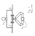
- Figure 1 is a schematic illustration of a prior art viscometer configuration.
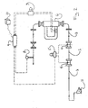
- Figure 2 is a schematic illustration of the preferred embodiment of the apparatus of the invention.
- Figure 3 is a flow chart showing a preferred embodiment of the software for performing the method of the invention.
- a prior art on-line viscometer is shown. Specifically, a Coriolis mass flow meter A, equipped with a differential pressure transducer B, is placed directly in the process flow path. Volumetric fluid flow rates are determined by dividing the fluid mass flow rate by the fluid density. The differential pressure transducer measures the pressure drop between a point upstream C of the meter and a point downstream D of the meter. The distance ⁇ L between points C and D is a known constant. Because of the looped configuration of a Coriolis meter, however, flow disturbances and entrance and exit effects occur in the pressure measurement section. These disturbances and effects lead to fluid flow in the measurement section that is not fully developed and uni-directional, resulting in inaccurate application of the Hagen-Poiseuille equation and Equation A.
- an apparatus having an improved flow path configuration. Because this improved flow path configuration prevents any flow entrance or exit effects and allows for fully developed, undisturbed, and uni-directional flow to occur, the assumptions underlying the Hagen-Poiseuille equation and Equation A are satisfied and improved accuracy in fluid viscosity determination is achieved.
- a preferred embodiment of the apparatus of the invention is schematically illustrated in Fig. 2.
- a substantially straight differential pressure measurement section with substantially uniform inside diameter is provided.
- the pressure measurement section comprises a differential pressure measurement flow tube 1, a preceding flow tube 2 upstream of the measurement flow tube, and a succeeding flow tube 3 downstream of the measurement flow tube.
- the inside diameters of both the preceding and succeeding flow tubes are substantially equal to that of the measurement flow tube.
- the measurement section may be one continuous tube or multiple tube sections connected with non-invasive means, so as to prevent flow disturbances from occurring at the inlet or exit of the measurement flow tube.
- the measurement section is substantially straight and level. It is noted that the measurement section is not required to be level; should it not be level, however, measured differential pressures through the section must be corrected.
- a differential pressure measurement device 5 is used to measure the pressure difference of the fluid between the inlet and the outlet of the measurement section. Any means may be used for measuring differential pressure in a substantially non-intrusive manner so that flow remains undisturbed.
- a Rosemount 3051C differential pressure transducer is used.
- the two pressure taps for the differential pressure transducer are preferably made with WIKA Type 981.10 seals 4, with one located at the inlet of the measurement flow tube, and one at the outlet of the measurement flow tube.
- the length of the pressure measurement flow tube 1 should be long enough that differential pressure measurements of a useful magnitude between its inlet and outlet occur. In one embodiment of the invention a measurement flow tube length of about 36 inches is used with the preferred Rosemount differential pressure transmitter and fluid flow rates between 5 and 60 gpm.
- the length of the preceding flow tube 2 should be such that fully developed, undisturbed and uni-directional flow occurs at the inlet of the measurement flow tube.
- the length of the succeeding flow tube 3 should be sufficient to avoid exit effects in the pressure measurement flow tube.
- a length equal to at least 15 times tube inside diameter has been determined to be acceptable.
- a succeeding flow tube length of 40 inches is used.
- a non-intrusive means for measuring fluid flow rate is in line with, located either upstream or downstream of the differential pressure measurement section.
- the flow rate measuring means is located away from the pressure measurement section so as not to cause, any flow disturbances within the measurement section. Any means may be used for determining the volumetric flow rate of the fluid.
- the fluid flow rate measuring means 6 comprises a Micro Motion ELITE CMF200 Coriolis mass flow meter with fluid density measuring capabilities located downstream of the succeeding flow tube section, in combination with a Micro Motion ELITE RFT9739 Mass Flow and Density Transmitter 7. Volumetric fluid flow rates are determined by dividing measured fluid mass flow rates by measured fluid densities.
- Coriolis mass flow meter is preferred, the present invention should not be construed as being limited to the Coriolis mass flow meter. There are various and sundry devices known to those skilled in the art for measuring or otherwise determining volumetric flow rate, which may be employed in lieu of the preferred Coriolis mass flow meter.
- Fluid is conveyed through the differential pressure measurement section and flow rate measuring means via a pump 11 or other means for providing and/or regulating fluid flow. Substantially steady and non-fluctuating flow is desired.
- the preferred embodiment of the invention uses a Moyno positive displacement pump for this purpose. It should be understood that one or more devices other than a pump could be employed to regulate fluid flow, such as a valve or throttle.
- the temperature of the fluid near the differential pressure measurement section and flow rate measuring section is measured using an instrument 8. Temperature data are not used directly to calculate viscosity, but as viscosity can vary greatly with temperature, temperature data are useful. Also, temperature measurements may be useful for compensating differential pressure, flow rate, and density measurements.
- the temperature measurement instrument comprises a resistance temperature detector probe placed downstream of the flow rate measuring means.
- the differential pressure measuring means, flow rate measuring means, and temperature measuring means each have an output signal conveying measured values.
- This preferred embodiment further comprises conversion means 9 to convert the output signals from analog to digital, and a microcomputer 10 to receive, convert, calculate, dynamically display and record values including the fluid viscosity, mass flow rate, density, differential pressure, temperature, Reynolds number and velocity.
- Figure 3 is a flow chart showing a preferred embodiment of the software performing a method of the invention.
- the program begins and first sets a flow iteration counter i equal to 1 (21). This flow iteration variable will be changed for each successive flow rate of the several to be run for power law constant determination purposes.
- the program then enters an input signal sampling loop and sets a second iteration counter N equal to 1 (22) to keep track of the number of times through the input signal sampling loop. This loop will read input signals over its multitude of iterations to smooth out any fluctuations in a given flow rate.
- the program then adjusts ⁇ p for temperature T 25.
- Running sum totals of ⁇ p , T, MFR, and ⁇ are kept 26, and the loop iteration counter N is increased by 1 (27) to indicate that a set of input signals has been read and added to the running sum totals.
- the program then makes a determination of whether or not to repeat this process of reading and summing input signals 28.
- a data file data raw (i) corresponding to the current flow rate is then created and stored 31 with values of log Q, (log Q) 2 , log ⁇ p , (log ⁇ p) 2 , (log ⁇ x log ⁇ p ), ( log ⁇ Q ⁇ log ⁇ p ), ⁇ , T and Re.
- the flow iteration counter "i" is increased 33 to indicate that a different flow will next be measured, and the program loops back to 22 to repeat measurements at another flow rate.
- the program will begin the process of determining the power law viscosity equation constants for the non-Newtonian fluid being investigated.
- the well known least squares fit model will be utilized to determine a best fit linear slope and y axis intercept for the pressure differential verse flow rate data.
- the program will first retrieve the stored log Q , (log Q) 2 , log ⁇ p and (log ⁇ p) 2 for each of the different flow rates stored in the respective raw data (i) files 35. Each of these 4 retrieved values is then summed over the several flow rates 36, with these summed totals stored to a newly created "calculated data" file 37.
- n (S xy /S xx )
- R 2 (S xy ) 2 /((S xx )(S yy ))
- the second power law constant k is then solved 43.
- Calculated values of n, (n-l), k, ln k, and R 2 are then saved to a newly created "Calculated data #2" file 44.
Landscapes
- Physics & Mathematics (AREA)
- Health & Medical Sciences (AREA)
- Life Sciences & Earth Sciences (AREA)
- Chemical & Material Sciences (AREA)
- Analytical Chemistry (AREA)
- Biochemistry (AREA)
- General Health & Medical Sciences (AREA)
- General Physics & Mathematics (AREA)
- Immunology (AREA)
- Pathology (AREA)
- Measuring Volume Flow (AREA)
Priority Applications (1)
| Application Number | Priority Date | Filing Date | Title |
|---|---|---|---|
| EP00104853A EP1134575A1 (fr) | 2000-03-07 | 2000-03-07 | Systeme de mesure de viscosité en ligne |
Applications Claiming Priority (1)
| Application Number | Priority Date | Filing Date | Title |
|---|---|---|---|
| EP00104853A EP1134575A1 (fr) | 2000-03-07 | 2000-03-07 | Systeme de mesure de viscosité en ligne |
Publications (1)
| Publication Number | Publication Date |
|---|---|
| EP1134575A1 true EP1134575A1 (fr) | 2001-09-19 |
Family
ID=8168048
Family Applications (1)
| Application Number | Title | Priority Date | Filing Date |
|---|---|---|---|
| EP00104853A Withdrawn EP1134575A1 (fr) | 2000-03-07 | 2000-03-07 | Systeme de mesure de viscosité en ligne |
Country Status (1)
| Country | Link |
|---|---|
| EP (1) | EP1134575A1 (fr) |
Cited By (6)
| Publication number | Priority date | Publication date | Assignee | Title |
|---|---|---|---|---|
| US7752895B2 (en) | 2006-11-30 | 2010-07-13 | Chevron Oronite S.A. | Method for using an alternate pressure viscometer |
| CN109031941A (zh) * | 2018-06-15 | 2018-12-18 | 营口康辉石化有限公司 | 树脂粘度控制系统及检测方法 |
| CN113566908A (zh) * | 2021-08-02 | 2021-10-29 | 河北大学 | 一种用于测量微小流量的差压流量计及测量方法 |
| WO2021249897A1 (fr) * | 2020-06-12 | 2021-12-16 | Covestro Deutschland Ag | Procédé permettant de déterminer un coefficient dans un calcul de viscosité de polymère thermoplastique |
| CN119000434A (zh) * | 2024-10-24 | 2024-11-22 | 成都洋湃科技有限公司 | 一种差压式在线粘度测量方法和稠油混相质量流量计 |
| WO2025131466A1 (fr) * | 2023-12-22 | 2025-06-26 | Endress+Hauser Flowtec Ag | Procédé de détermination d'une valeur de viscosité mesurée, et débitmètre massique à effet coriolis pour la mise en œuvre du procédé |
Citations (10)
| Publication number | Priority date | Publication date | Assignee | Title |
|---|---|---|---|---|
| US3924448A (en) * | 1974-06-19 | 1975-12-09 | Us Navy | Pressure drop polymer concentration meter (pcm) |
| US4165632A (en) * | 1976-03-27 | 1979-08-28 | Torsten Kreisel | Method of measuring the fluidity of liquids for medical and pharmaceutical purposes, and apparatus for performing the method |
| US4573345A (en) * | 1984-07-12 | 1986-03-04 | Mobil Oil Corporation | Melt rheometer control |
| US4726219A (en) * | 1986-02-13 | 1988-02-23 | Atlantic Richfield Company | Method and system for determining fluid pressures in wellbores and tubular conduits |
| US4750351A (en) * | 1987-08-07 | 1988-06-14 | The United States Of America As Represented By The Secretary Of The Army | In-line viscometer |
| EP0595276A2 (fr) * | 1992-10-28 | 1994-05-04 | Göttfert Werkstoff-Prüfmaschinen Gmbh | Méthode et appareil de mesure de la viscosité en continu |
| WO1996001988A1 (fr) * | 1994-07-08 | 1996-01-25 | The Dow Chemical Company | Procede et appareil de mesure en service de proprietes rheologiques |
| US5597949A (en) * | 1995-09-07 | 1997-01-28 | Micro Motion, Inc. | Viscosimeter calibration system and method of operating the same |
| US5637790A (en) * | 1996-02-28 | 1997-06-10 | De Corral; Jose L. | Three capillary flow-through viscometer |
| US5877409A (en) * | 1997-06-06 | 1999-03-02 | Mobil Oil Corporation | Method and system for determining viscosity index |
-
2000
- 2000-03-07 EP EP00104853A patent/EP1134575A1/fr not_active Withdrawn
Patent Citations (10)
| Publication number | Priority date | Publication date | Assignee | Title |
|---|---|---|---|---|
| US3924448A (en) * | 1974-06-19 | 1975-12-09 | Us Navy | Pressure drop polymer concentration meter (pcm) |
| US4165632A (en) * | 1976-03-27 | 1979-08-28 | Torsten Kreisel | Method of measuring the fluidity of liquids for medical and pharmaceutical purposes, and apparatus for performing the method |
| US4573345A (en) * | 1984-07-12 | 1986-03-04 | Mobil Oil Corporation | Melt rheometer control |
| US4726219A (en) * | 1986-02-13 | 1988-02-23 | Atlantic Richfield Company | Method and system for determining fluid pressures in wellbores and tubular conduits |
| US4750351A (en) * | 1987-08-07 | 1988-06-14 | The United States Of America As Represented By The Secretary Of The Army | In-line viscometer |
| EP0595276A2 (fr) * | 1992-10-28 | 1994-05-04 | Göttfert Werkstoff-Prüfmaschinen Gmbh | Méthode et appareil de mesure de la viscosité en continu |
| WO1996001988A1 (fr) * | 1994-07-08 | 1996-01-25 | The Dow Chemical Company | Procede et appareil de mesure en service de proprietes rheologiques |
| US5597949A (en) * | 1995-09-07 | 1997-01-28 | Micro Motion, Inc. | Viscosimeter calibration system and method of operating the same |
| US5637790A (en) * | 1996-02-28 | 1997-06-10 | De Corral; Jose L. | Three capillary flow-through viscometer |
| US5877409A (en) * | 1997-06-06 | 1999-03-02 | Mobil Oil Corporation | Method and system for determining viscosity index |
Cited By (7)
| Publication number | Priority date | Publication date | Assignee | Title |
|---|---|---|---|---|
| US7752895B2 (en) | 2006-11-30 | 2010-07-13 | Chevron Oronite S.A. | Method for using an alternate pressure viscometer |
| CN109031941A (zh) * | 2018-06-15 | 2018-12-18 | 营口康辉石化有限公司 | 树脂粘度控制系统及检测方法 |
| WO2021249897A1 (fr) * | 2020-06-12 | 2021-12-16 | Covestro Deutschland Ag | Procédé permettant de déterminer un coefficient dans un calcul de viscosité de polymère thermoplastique |
| CN113566908A (zh) * | 2021-08-02 | 2021-10-29 | 河北大学 | 一种用于测量微小流量的差压流量计及测量方法 |
| CN113566908B (zh) * | 2021-08-02 | 2023-08-15 | 河北大学 | 一种用于测量微小流量的差压流量计及测量方法 |
| WO2025131466A1 (fr) * | 2023-12-22 | 2025-06-26 | Endress+Hauser Flowtec Ag | Procédé de détermination d'une valeur de viscosité mesurée, et débitmètre massique à effet coriolis pour la mise en œuvre du procédé |
| CN119000434A (zh) * | 2024-10-24 | 2024-11-22 | 成都洋湃科技有限公司 | 一种差压式在线粘度测量方法和稠油混相质量流量计 |
Similar Documents
| Publication | Publication Date | Title |
|---|---|---|
| Tu et al. | Fully developed periodic turbulent pipe flow. Part 1. Main experimental results and comparison with predictions | |
| US4750351A (en) | In-line viscometer | |
| US6681189B1 (en) | Method and system for determining flow rates and/or fluid density in single and multiple-phase flows utilizing discharge coefficient relationships | |
| AU2008355583B2 (en) | Method for generating a diagnostic from a deviation of a flow meter parameter | |
| EP2192391A1 (fr) | Appareil et procédé pour mesure l'écoulement d'un fluide | |
| US6196058B1 (en) | On-line viscosity measurement system | |
| RU2503928C2 (ru) | Способ определения расходов первой газообразной фазы и, по меньшей мере, второй жидкой фазы, присутствующих в многофазной текучей среде | |
| DE102007062908A1 (de) | Verfahren und System zur Bestimmung mindestens einer Prozessgröße eines strömenden Mediums | |
| EP1134575A1 (fr) | Systeme de mesure de viscosité en ligne | |
| JPH0654287B2 (ja) | パイプラインにおける非ニユ−トン性の測定装置 | |
| NO20171056A1 (en) | Ultrasonic viscometer | |
| Cascetta et al. | Field test of a swirlmeter for gas flow measurement | |
| Fyrippi et al. | Flowmetering of non-Newtonian liquids | |
| CA2300031A1 (fr) | Systeme en ligne de mesure de viscosite | |
| JPH08261906A (ja) | スタティックミキサを用いた粘度測定装置及び粘度測定方法 | |
| RU2378638C2 (ru) | Плотномер-расходомер жидких сред | |
| CN119670324A (zh) | 一种油井采出物多相计量建模系统和多相计量方法 | |
| Johnson et al. | Development of a turbine meter for two-phase flow measurement in vertical pipes | |
| CN119670322A (zh) | 一种油井多相采出介质流量计量模型建立系统和计量方法 | |
| RU2743511C1 (ru) | Поточный способ для измерения вязкости ньютоновских и неньютоновских жидкостей с помощью щелевого сужающего устройства | |
| JP2005147682A (ja) | 流量計及び流量計測法 | |
| RU73485U1 (ru) | Плотномер-расходомер жидких сред | |
| Pistun et al. | Mathematical Models of Throttle Elements of Gas-hydrodynamic Measuring Transducers | |
| CN119666660B (zh) | 一种油井多相采出物相分率计量模型建立系统和计量方法 | |
| Harrouz et al. | Control information and analyzing of metering gas system based of orifice plate |
Legal Events
| Date | Code | Title | Description |
|---|---|---|---|
| PUAI | Public reference made under article 153(3) epc to a published international application that has entered the european phase |
Free format text: ORIGINAL CODE: 0009012 |
|
| AK | Designated contracting states |
Kind code of ref document: A1 Designated state(s): AT BE CH CY DE DK ES FI FR GB GR IE IT LI LU MC NL PT SE |
|
| AX | Request for extension of the european patent |
Free format text: AL;LT;LV;MK;RO;SI |
|
| RAP1 | Party data changed (applicant data changed or rights of an application transferred) |
Owner name: STORA ENSO NORTH AMERICA CORPORATION |
|
| 17P | Request for examination filed |
Effective date: 20020225 |
|
| AKX | Designation fees paid |
Free format text: AT BE CH CY DE DK ES FI FR GB GR IE IT LI LU MC NL PT SE |
|
| STAA | Information on the status of an ep patent application or granted ep patent |
Free format text: STATUS: THE APPLICATION IS DEEMED TO BE WITHDRAWN |
|
| 18D | Application deemed to be withdrawn |
Effective date: 20031001 |