EP1135860B1 - Verfahren zur Überwachung einer SCHALTUNGSANORDNUNG mit A/D-WANDLER FÜR SICHERHEITSKRITISCHE ANWENDUNGEN - Google Patents
Verfahren zur Überwachung einer SCHALTUNGSANORDNUNG mit A/D-WANDLER FÜR SICHERHEITSKRITISCHE ANWENDUNGEN Download PDFInfo
- Publication number
- EP1135860B1 EP1135860B1 EP99961021A EP99961021A EP1135860B1 EP 1135860 B1 EP1135860 B1 EP 1135860B1 EP 99961021 A EP99961021 A EP 99961021A EP 99961021 A EP99961021 A EP 99961021A EP 1135860 B1 EP1135860 B1 EP 1135860B1
- Authority
- EP
- European Patent Office
- Prior art keywords
- ramp
- voltage
- converter
- output voltage
- delta
- Prior art date
- Legal status (The legal status is an assumption and is not a legal conclusion. Google has not performed a legal analysis and makes no representation as to the accuracy of the status listed.)
- Expired - Lifetime
Links
Images


Classifications
-
- H—ELECTRICITY
- H03—ELECTRONIC CIRCUITRY
- H03M—CODING; DECODING; CODE CONVERSION IN GENERAL
- H03M1/00—Analogue/digital conversion; Digital/analogue conversion
- H03M1/10—Calibration or testing
- H03M1/1071—Measuring or testing
- H03M1/109—Measuring or testing for DC performance, i.e. static testing
-
- H—ELECTRICITY
- H03—ELECTRONIC CIRCUITRY
- H03M—CODING; DECODING; CODE CONVERSION IN GENERAL
- H03M1/00—Analogue/digital conversion; Digital/analogue conversion
- H03M1/12—Analogue/digital converters
Definitions
- the invention relates to a method for monitoring a circuit arrangement with a A / D converter especially for safety-critical applications.
- Such a component to be monitored for error-free operation is, for example, an A / D (analog / digital) converter. It is known to operate two identical A / D converters in parallel, the output signals of both converters for equality monitor and generate an error message when the Equality - taking into account the usual converter tolerances - no longer exists. Because an A / D converter in particular with higher demands on speed and accuracy but is relatively complex to implement, For cost reasons, this solution is generally called viewed disadvantageously.
- WO 97 49188 A relates to a method for testing an A / D converter, in which only the LSB of the A / D converter is considered. A complete sweep of the voltage range therefore does not take place.
- the invention is based on the object Specify method for monitoring a circuit arrangement with an A / D converter, at which is required for safety-critical applications Monitoring the function of the A / D converter with less Circuit effort is possible.
- a particular advantage of this solution is that through the reference measurement in the first pass and thereby possible compensation of different tolerances of the Ramp signal generator whose circuitry is relatively low can be held.
- the second criterion is a test for clock failure.
- the third criterion is the temporal behavior of the A / D converter, with regard to the position of the sampling frequency within a permissible tolerance range, as well as with regard to a correct determination of the sample values in normal operation.
- the fourth criterion is used to monitor the reference voltage of the A / D converter.
- FIG. 1 A basic circuit diagram of a corresponding circuit arrangement according to the invention is shown in FIG. 1.
- a ramp signal generator 11 is connected to the input of an A / D converter 10 to be monitored.
- a test circuit is present at the output of the A / D converter 10.
- the A / D converter 10 converts the analog ramp voltage u in present at its input, which is shown in FIG. 2, into a digital output voltage u out , which is evaluated with the test circuit 12.
- the test circuit is triggered by the sampling signal f s of the A / D converter and generates a discharge signal E for the relevant capacitor of the ramp signal generator.
- m (u max * f s ) / c1, where u max is the maximum ramp voltage and cl is the counter reading when u max is reached.
- the basic principle in the solution according to the invention is to run the ramp voltage u in at the input of the A / D converter 10 twice and to carry out various measurements with respect to the output signals u out.
- the time period is measured that the ramp signal generator 11 needs to change the ramp voltage from a negative reference voltage -U Ref or the value zero (ground) to the ramp stop, that is to say up to the positive reference voltage + U Ref or u increase max .
- This time period is recorded as a multiple of the sampling time of the A / D converter.
- This measurement is used to eliminate different tolerances of the ramp signal generator 11 from the results of the second pass.
- a second run is now used to check whether different Transmission characteristics of the A / D converter in the specified Tolerance range.
- This run described three different methods, depending on which of the desired accuracy and reliability one or more can be performed.
- the first run begins with an initialization (I) with which the capacitor of the ramp signal generator is discharged with the discharge signal E (FIG. 1) and a first counter is reset. While the ramp voltage then rises, a first counter counts the scanning signals. If a ramp stop is not found after a certain time (reaching a maximum counter reading c1 max ), an error signal F is generated. If a ramp stop is detected, the test circuit goes into the setup state (S). At the end of this first run it is checked whether the maximum ramp voltage u max reached is within a specified tolerance range ("full scale error"). If this is not the case, the error signal F is generated.
- the capacitor of the ramp signal generator is discharged again and - if the A / D converter has a calculation time (latency time) of one sampling time - a waiting state (W) inserted.
- FIG. 4 shows the flow diagram of the course of states I. (Initialization) and T (time measurement) with the test circuit be carried out for all three procedures are the same.
- the initialization I begins with a step S1 with the Generation of the discharge signal E for the capacitor C des Ramp signal generator. Then one step S2 the status c1 of a first counter is reset, namely to a value of -2, causing delays by the algorithm and the calculation time of the A / D converter (Latent time) can be compensated. In addition, with a Step S3 the level c2 of a second counter is set to zero.
- the subsequent time measurement (T) runs in two loops and begins with one. Zeroing the discharge signal E with a step S4.
- the status c1 of the first counter with which the number of samples is counted until the ramp is reached, is increased by the value 1 and, according to step S6, the output voltage u out of the A / D converter is stored as the value u old .
- the system waits until a new scanning signal occurs, so that there is a new converted value in U out (see page 5, below).
- a step S7 queries whether the new value u out of the output voltage is equal to the old value u old .
- step S8 the status c2 of the second counter is set to zero in step S8 and a query is made in step S9 as to whether the status c1 of the first counter has reached its maximum value c1 max . If this is not the case, this process is repeated starting with step S4, since on the one hand the output voltage u out still changes with each scan and on the other hand the number of scans c1 max required to reach the ramp stop has not yet been reached.
- step S9 If, on the other hand, the query in step S9 is answered with "yes", that is to say when the maximum number c1 max of scans, which is also necessary for the worst case, has been reached, at which the ramp stop should be reached guaranteed with a faultless A / D converter, according to step S10, an error message is generated due to the ramp stop not being reached, and the sequence is repeated, starting with the initialization (I).
- step S7 As soon as the output voltage u out of the A / D converter no longer changes compared to the previous sampling and the answer to the query in step S7 must therefore be "yes”, the status c2 of the second counter is increased by the value 1 and step S11 asked in step S12 whether this new counter reading is equal to the value of t delta-max , that is to say the number of samples in which, in the worst case, the output voltage u out is guaranteed to increase by 1 LSB during the rise in the ramp voltage. If this query is answered with "no”, the time measurement T is repeated and the process continues with step S4. If, on the other hand, the query is answered with "yes”, ie the ramp stop has been reached, the test machine goes into state S ("setup").
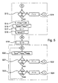
- FIG. 5 now shows the second part (states S, W and M according to FIG. 3) of the further procedure for the first method.
- the setup state S begins with the query in step S13 whether the measured ramp stop voltage u out lies outside the tolerance range u FS , where u FS is the output value of the A / D converter at the end of the range ("full scale"). If this is the case, an error signal F is set to the value 1 with step S14 and the sequence with the initialization I according to FIG. 4 is repeated.
- the test machine then takes the waiting state W and sets the discharge signal E with step S19 for the capacitor of the Ramp signal generator to zero.
- step S21 it is then queried whether the output voltage u out lies outside the tolerance range of the comparison voltage u plus . If this is the case, an error signal F is set to the value 1 in step S22 and the sequence with the initialization I according to FIG. 4 is repeated.
- step S21 If the query in step S21 is answered with "no”, it is queried in step S23 whether the comparison voltage u plus is within the tolerance range of the maximum output voltage u max . If this query is answered with "yes”, the error signal F is set to the value 0 in step S24. In this case, the ramp stop has been reached and the measurement is concluded as error-free, since, according to step S21, the measured output voltage u out is not outside the tolerance range of the calculated comparison voltage u plus . The entire sequence can then be repeated with the initialization I according to FIG. 4.
- step S23 If the answer in step S23 is "no" the frame stop has not yet been reached, and the Voltage measurement is made by returning the process to the beginning of state M repeated.
- FIG. 6 shows the second part of the sequence (states S, W and M) for the above-mentioned second method.
- This calculation is carried out by a division or a shift operation by n bits to the right, provided the reference voltage U Ref of the A / D converter is used as the maximum ramp voltage u max (in this case, the measurement of u max can be dispensed with, since this is already known up to the tolerance range [full scale error]).
- the process in state S begins with a query in step S25 as to whether the output voltage of the A / D converter is outside the tolerance range u FS . If this is the case, the error signal F is set to the value 1 in step S26 and the process is continued by returning to the initialization I. If the query is answered with "no", the value t delta is calculated as indicated above with step S27. Then, in step S28, the discharge signal E for the capacitor of the ramp signal generator is set to the value 1, in step S29 the value of the comparison voltage u plus determined by calculation is set to the value 0, and in step S30 the position c2 of the second counter is also set to the value 0 set.
- step S31 the discharge signal E for the capacitor of the ramp signal generator set to the value 0.
- step S32 it is first queried in step S32 whether the position c2 of the second counter corresponds to the time period t delta . If this is not the case, the position c2 is incremented by 1 using the loop formed by step S36 until the query in step S32 is answered with "yes". In this case, the counter reading is then set to the value 1 with step S33 and the comparison voltage u plus is incremented by the value 1 with step S34.
- a step S35 then follows whether the output voltage u out lies outside the tolerance range of the comparison voltage u plus . If this is the case, the error signal F is set to the value 1 in step S37 and the process is repeated by returning to the initialization I (FIG. 4).
- step S38 If the output voltage u out is not outside the tolerance range of the comparison voltage u plus , a query is made in step S38 as to whether the comparison voltage u plus lies within the tolerance range of the ramp stop voltage u FS . If this query is answered with "yes", the error signal F is set to the value 0 in step S39 and the sequence is continued by returning to the initialization I. In the other case, there is a jump back to the beginning of the measurement state M.
- An advantage of the second method is that in Compared to the first method, there is no divider can be. Furthermore, the adder can be reduced Word range.
- the third method detects times at certain voltage changes and checks whether these times are within the tolerance ranges. For this purpose, the minimum and maximum number of samples between two voltage changes at the output are calculated using the measured state cl of the first counter and the maximum output voltage u max (at u max ⁇ > U Ref ) in the setup state S. of the A / D converter, taking into account all converter inaccuracies, is just within the tolerable range.
- the measuring state M the after every voltage change Counter reset and incremented until on Output of the A / D converter the next voltage change occurs. Then it is checked whether the meter reading in one Range between minimum and maximum number of samples stands that is tolerable for this voltage change and whether the differential voltage change in the approved Area. This third process takes place no error propagation due to the reset of the counter instead, so that worked with a smaller word width can be.
- this procedure must take into account that the time between two voltage changes as a multiple the sampling time is measured.
- this corresponds just a measurement of the differential nonlinearity (DNL) in the form of a relative measurement between two samples. Absolute deviations from the ideal Transmission characteristic curve due to the integral non-linearity INL are not included.
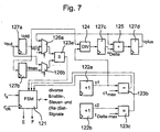
- FIG. 7 shows a possible block diagram of a test machine 12 to carry out the first method.
- the circuit is digitized and essentially comprises a control unit 121, a first and a second counter 122a, 122b, a first, a second and a third comparator 123a, 123b, 123c, a divider 124, an adder 125, a first and a second multiplexer 126a, 126b, and a first to fourth register 127a, 127b, 127c, 127d.
- the control unit 121 at which the sampling frequency f s and a clock frequency f ' clk are present, generates the discharge signal E for the capacitor of the ramp signal generator, the error signal F and various other control, reset and release signals.
- the output voltage u out of the A / D converter is present at the first register 127a and at a first input of the second multiplexer 126b.
- the output of the first register 127a is connected as a voltage value u old to a first input of the first multiplexer 126a, the input of the second register 127b, and a first input of the divider 124.
- the output of the second register 127b is present at a second input of the second multiplexer 126b.
- the outputs of the first and second multiplexers 126a, 126b are each connected to an input of the first comparator 123a, with which the input signals are compared for equality, taking into account the tolerance ranges.
- the output of the first comparator 123a is connected to the control unit 121.
- the output of the first counter 122a is connected as a counter reading cl to a second input of the divider 124 and a first input of the second comparison 123b.
- the output of the second counter 122b is connected as a count c2 to a first input of the third comparator 123c.
- the maximum count value c1 max is present at a second input of the second comparison 123b, while the value t delta-max is supplied to a second input of the third comparison 123c.
- the outputs of the second and third comparators are connected to the control unit 121.
- the output of the divider 124 is present at the input of the third register 127c, the output of which is connected as a voltage value u delta to a first input of the adder 125.
- the output of the adder 125 is led to the input of the fourth register 127d, the output of which is connected as a voltage value u plus to a second input of the adder 125 and a second input of the first multiplexer 126a.
- the voltage value u FS is present at a third input of the first multiplexer 126a.
- the test machine can reduce the total circuit effort also realized by a computer program become.
Landscapes
- Engineering & Computer Science (AREA)
- Theoretical Computer Science (AREA)
- Analogue/Digital Conversion (AREA)
Description
Claims (5)
- Verfahren zur Überwachung einer Schaltungsanordnung mit A/D-Wandler für sicherheitskritische Anwendungen mit einem Rampensignalgenerator (11) zur Erzeugung einer dem Eingang des A/D-Wandlers (10) zugeführten Rampenspannung, sowie einer Testschaltung (12) zur Aktivierung eines Testzyklus', der einen ersten Durchlauf der Rampe umfaßt, mit dem eine Referenzmessung des Rampensignalgenerators zur Kompensation von Bauelement-Toleranzen durchgeführt wird, sowie einen zweiten Durchlauf der Rampe beinhaltet, bei dem ein Fehlersignal (F) ausgegeben wird, wenn der für eine Übertragungskenngröße des A/D-Wandlers (10) berechnete Wert außerhalb eines vorgegebenen Toleranzbereiches des gemessenen Wertes der Übertragungskenngröße liegt, dadurch gekennzeichnet, daß
die Rampe in jedem Rampendurchlauf vollständig durchlaufen wird und mit dem ersten Durchlauf der Rampe die Zeit gemessen wird, die für einen Rampendurchlauf erforderlich ist, wobei diese Zeit als eine Anzahl (c1) von Abtastungen bis zum Erreichen der maximalen Rampenspannung (umax) ermittelt wird. - Verfahren nach Anspruch 1, dadurch gekennzeichnet, daß mit dem ersten Durchlauf der Rampe Toleranzen einer Referenzspannung (URef) des A/D-Wandlers und der maximalen Rampenspannung (umax) sowie der Steigung (m) der Rampenspannung des Rampensignalgenerators kompensiert werden.
- Verfahren nach Anspruch 1 oder 2,
dadurch gekennzeichnet, daß die Übertragungskenngröße die für eine oder eine Mehrzahl (n) von Abtastungen berechnete Ausgangsspannung (uplus + n uDelta) ist und das Fehlersignal (F) erzeugt wird, wenn diese außerhalb eines vorgegebenen Toleranzbereiches der bei diesen Abtastungen gemessenen Ausgangsspannung (uout) liegt. - Verfahren nach Anspruch 1 oder 2,
dadurch gekennzeichnet, daß mit der Testschaltung die zur Änderung der Ausgangsspannung um 1 LSB erforderliche Zeitdauer (tDelta) berechnet und die Übertragungskenngröße die für eine oder eine Mehrzahl (n) von Zeitdauern (tDelta) berechnete Ausgangsspannung (uplus) ist und das Fehlersignal (F) erzeugt wird, wenn diese außerhalb eines vorgegebenen Toleranzbereiches der zu den betreffenden Zeitpunkten (n tDelta) gemessenen Ausgangsspannung (uout) liegt. - Verfahren nach Anspruch 1 oder 2,
dadurch gekennzeichnet, daß die Übertragungskenngröße die für eine Änderung der Ausgangsspannung (uout) um ein oder eine Mehrzahl von LSBs erforderliche Anzahl von Abtastungen ist und ein Fehlersignal (F) erzeugt wird, wenn diese Anzahl außerhalb eines vorgegebenen Toleranzbereiches der gezählten Anzahl von Abtastungen liegt.
Applications Claiming Priority (5)
| Application Number | Priority Date | Filing Date | Title |
|---|---|---|---|
| DE19855743 | 1998-12-03 | ||
| DE19855743 | 1998-12-03 | ||
| DE19912766A DE19912766A1 (de) | 1998-12-03 | 1999-03-22 | Schaltungsanordnung mit A/D-Wandler für sicherheitskritische Anwendungen |
| DE19912766 | 1999-03-22 | ||
| PCT/EP1999/009249 WO2000033465A1 (de) | 1998-12-03 | 1999-11-29 | Schaltungsanordnung zum testen eines a/d-wandlers für sicherheitskritische anwendungen |
Publications (2)
| Publication Number | Publication Date |
|---|---|
| EP1135860A1 EP1135860A1 (de) | 2001-09-26 |
| EP1135860B1 true EP1135860B1 (de) | 2003-04-02 |
Family
ID=26050531
Family Applications (1)
| Application Number | Title | Priority Date | Filing Date |
|---|---|---|---|
| EP99961021A Expired - Lifetime EP1135860B1 (de) | 1998-12-03 | 1999-11-29 | Verfahren zur Überwachung einer SCHALTUNGSANORDNUNG mit A/D-WANDLER FÜR SICHERHEITSKRITISCHE ANWENDUNGEN |
Country Status (4)
| Country | Link |
|---|---|
| US (1) | US6518900B1 (de) |
| EP (1) | EP1135860B1 (de) |
| JP (1) | JP2002531986A (de) |
| WO (1) | WO2000033465A1 (de) |
Families Citing this family (9)
| Publication number | Priority date | Publication date | Assignee | Title |
|---|---|---|---|---|
| JP4354906B2 (ja) | 2002-05-08 | 2009-10-28 | コンティネンタル・テーベス・アクチエンゲゼルシヤフト・ウント・コンパニー・オッフェネ・ハンデルスゲゼルシヤフト | エラーのない信号アナログ・デジタル変換のための電子回路 |
| DE10314616B3 (de) * | 2003-04-01 | 2004-07-01 | Infineon Technologies Ag | Integrierte Schaltung mit einer Testschaltung |
| DE10335164B4 (de) | 2003-07-30 | 2007-03-22 | Infineon Technologies Ag | Vorrichtung und Verfahren zum parallelen Testen von mehreren integrierten Schaltkreisen |
| JP3861874B2 (ja) * | 2003-12-16 | 2006-12-27 | 株式会社デンソー | Ad変換器の故障検出装置 |
| JP4140534B2 (ja) * | 2004-02-27 | 2008-08-27 | 株式会社デンソー | A/d変換装置 |
| TWI375806B (en) * | 2007-08-07 | 2012-11-01 | Himax Tech Ltd | Apparatus for testing driving circuit in display |
| JP2010103737A (ja) * | 2008-10-23 | 2010-05-06 | Toshiba Corp | Adcテスト回路 |
| US8106801B2 (en) * | 2009-02-12 | 2012-01-31 | Qualcomm, Incorporated | Methods and apparatus for built in self test of analog-to-digital convertors |
| US10637494B2 (en) * | 2017-11-02 | 2020-04-28 | Microchip Technology Incorporated | ADC self-test using time base and current source |
Family Cites Families (17)
| Publication number | Priority date | Publication date | Assignee | Title |
|---|---|---|---|---|
| US3816813A (en) * | 1972-01-24 | 1974-06-11 | Spacetac Inc | Automatic converter tester |
| US4352160A (en) * | 1980-01-21 | 1982-09-28 | The United States Of America As Represented By The Secretary Of The Air Force | Statistical method of measuring the differential linearity of an analog/digital converter using a pseudo-random triangle wave stimulus |
| DE3218066A1 (de) * | 1981-07-08 | 1983-01-27 | Siemens AG, 1000 Berlin und 8000 München | Verfahren zur pruefung von analog-digital-wandlern und/oder von digital-analog-wandlern oder von nachrichtentechnischen uebertragungsabschnitten, die solche wandler enthalten oder mit ihnen in reihe geschaltet sind, insbsondere zur pruefung von codecs fuer pcm-geraete, sowie vorrichtung zur durchfuehrung des verfahrens |
| US4989686A (en) | 1988-07-07 | 1991-02-05 | Borg-Warner Automotive, Inc. | System for controlling torque transmission in a four wheel drive vehicle |
| US5017789A (en) | 1989-03-31 | 1991-05-21 | Loma Linda University Medical Center | Raster scan control system for a charged-particle beam |
| EP0420082B1 (de) | 1989-09-29 | 1997-02-19 | Hewlett-Packard Company | Digital synchronisierte Quelle für ein Wobbelsignal |
| DE69124709T2 (de) * | 1990-03-15 | 1997-05-28 | At & T Corp | Eingebaute Selbstprüfung für Analog-Digitalumsetzer |
| DE69128509T2 (de) | 1990-09-28 | 1998-05-14 | Yokogawa Electric Corp | Zeitgeber |
| DE4311858C2 (de) | 1993-04-10 | 1996-05-30 | Brauch Elektronik Gmbh & Co Kg | Verfahren und Einrichtung zur Qualitätsüberwachung von Aufzeichnungsträgern |
| US5432352A (en) | 1993-09-20 | 1995-07-11 | Eaton Corporation | Ion beam scan control |
| US5764541A (en) | 1995-12-22 | 1998-06-09 | Hermann Finance Corporation Ltd. | Microprocessor controlled sensor signal conditioning circuit |
| JP3597303B2 (ja) * | 1996-04-23 | 2004-12-08 | 株式会社ルネサステクノロジ | A/dコンバータのテスト方法及びテスト装置 |
| US5659312A (en) * | 1996-06-14 | 1997-08-19 | Logicvision, Inc. | Method and apparatus for testing digital to analog and analog to digital converters |
| TW364950B (en) * | 1996-06-17 | 1999-07-21 | Koninkl Philips Electronics Nv | Method of testing an analog-to-digital converter |
| US5663638A (en) | 1996-07-29 | 1997-09-02 | Hewlett-Packard Company | Calorimetric RF power meter with dynamic zeroing and constant temperature and power dissipation in the calorimetric bridge |
| DE19634049C2 (de) | 1996-08-23 | 1999-09-02 | Temic Semiconductor Gmbh | Verfahren zur Meßwerterfassung |
| US6333706B1 (en) * | 1999-08-02 | 2001-12-25 | International Business Machines Corporation | Built-in self-test for analog to digital converter |
-
1999
- 1999-11-29 EP EP99961021A patent/EP1135860B1/de not_active Expired - Lifetime
- 1999-11-29 JP JP2000586000A patent/JP2002531986A/ja not_active Withdrawn
- 1999-11-29 WO PCT/EP1999/009249 patent/WO2000033465A1/de not_active Ceased
- 1999-11-29 US US09/857,282 patent/US6518900B1/en not_active Expired - Fee Related
Also Published As
| Publication number | Publication date |
|---|---|
| JP2002531986A (ja) | 2002-09-24 |
| US6518900B1 (en) | 2003-02-11 |
| WO2000033465A1 (de) | 2000-06-08 |
| EP1135860A1 (de) | 2001-09-26 |
Similar Documents
| Publication | Publication Date | Title |
|---|---|---|
| DE10116380B4 (de) | Halbleiterprüfsystem | |
| DE69215456T2 (de) | Vorrichtung für Zeitinterpolation | |
| DE60204597T2 (de) | Kompakter automatischer tester (ate) mit zeitstempel-system | |
| DE3201297C2 (de) | ||
| EP1135860B1 (de) | Verfahren zur Überwachung einer SCHALTUNGSANORDNUNG mit A/D-WANDLER FÜR SICHERHEITSKRITISCHE ANWENDUNGEN | |
| DE2220878A1 (de) | Schaltungsanordnung zur digitalen frequenzmessung | |
| DE2836723A1 (de) | Zeitsteuerschaltung | |
| DE102008059791A1 (de) | Automatisch-mittelnde RC-Zeitkonstanten-Kalibrierung | |
| EP0017251B1 (de) | Schaltungsanordnung für die Bestimmung der mittleren Periodendauer eines periodischen Signals | |
| DE3935617A1 (de) | Infrarot-fouriertransformations-spektrometer | |
| DE3619558A1 (de) | Verfahren und vorrichtung zur kapazitaetsmessung | |
| DE19828399C1 (de) | Einrichtung zur schnellen D/A-Wandlung von PWM-Signalen | |
| DE102019202472A1 (de) | Verifizierung einer Sensormessung in Quasi-Echtzeit | |
| EP1397694B1 (de) | Verfahren zur überwachung einer spannungsversorgung eines steuergeräts in einem kraftfahrzeug | |
| EP0753756A2 (de) | Schaltungsanordnung und Verfahren zum Messen eines Kapazitätsunterschiedes zwischen einer ersten Kapazität C1 und einer zweiten Kapazität C2 | |
| EP0729583A1 (de) | Phasenmessvorrichtung | |
| EP0515438B1 (de) | Verfahren zum umsetzen einer analogen spannung in einen digitalwert | |
| DE19912766A1 (de) | Schaltungsanordnung mit A/D-Wandler für sicherheitskritische Anwendungen | |
| DE2547725A1 (de) | Analog-digital-wandler | |
| DE19631972C2 (de) | Verfahren zum Überwachen der Funktionsfähigkeit eines zur Digitalisierung von Analogsignalen ausgelegten Analog/-Digital Wandlers | |
| EP2190121B1 (de) | Mehrkanaliger AD-Wandler | |
| EP1636906B1 (de) | Elektronischer schaltkreis zur messgrössenerfassung | |
| DE10332008B4 (de) | Elektrische Schaltung sowie Verfahren zum Testen von elektronischen Bauteilen | |
| EP2627974B1 (de) | Verfahren, schaltungsanordnung und überwachungsvorrichtung zur signalprüfung | |
| DE102024204534B3 (de) | Komparatorschaltung-selbsttest |
Legal Events
| Date | Code | Title | Description |
|---|---|---|---|
| PUAI | Public reference made under article 153(3) epc to a published international application that has entered the european phase |
Free format text: ORIGINAL CODE: 0009012 |
|
| 17P | Request for examination filed |
Effective date: 20010703 |
|
| AK | Designated contracting states |
Kind code of ref document: A1 Designated state(s): AT BE CH CY DE DK ES FI FR GB GR IE IT LI LU MC NL PT SE |
|
| 17Q | First examination report despatched |
Effective date: 20010925 |
|
| RTI1 | Title (correction) |
Free format text: METHOD FOR TESTING A CIRCUIT WITH A/D CONVERTER FOR APPLICATIONS THAT ARE CRITICAL IN TERMS OF SAFETY |
|
| GRAH | Despatch of communication of intention to grant a patent |
Free format text: ORIGINAL CODE: EPIDOS IGRA |
|
| GRAH | Despatch of communication of intention to grant a patent |
Free format text: ORIGINAL CODE: EPIDOS IGRA |
|
| GRAA | (expected) grant |
Free format text: ORIGINAL CODE: 0009210 |
|
| AK | Designated contracting states |
Designated state(s): DE FR GB |
|
| PG25 | Lapsed in a contracting state [announced via postgrant information from national office to epo] |
Ref country code: GB Free format text: LAPSE BECAUSE OF FAILURE TO SUBMIT A TRANSLATION OF THE DESCRIPTION OR TO PAY THE FEE WITHIN THE PRESCRIBED TIME-LIMIT Effective date: 20030402 |
|
| REG | Reference to a national code |
Ref country code: GB Ref legal event code: FG4D Free format text: NOT ENGLISH |
|
| REG | Reference to a national code |
Ref country code: IE Ref legal event code: FG4D Free format text: GERMAN |
|
| REF | Corresponds to: |
Ref document number: 59904881 Country of ref document: DE Date of ref document: 20030508 Kind code of ref document: P |
|
| GBV | Gb: ep patent (uk) treated as always having been void in accordance with gb section 77(7)/1977 [no translation filed] |
Effective date: 20030402 |
|
| ET | Fr: translation filed | ||
| REG | Reference to a national code |
Ref country code: IE Ref legal event code: FD4D Ref document number: 1135860E Country of ref document: IE |
|
| PLBE | No opposition filed within time limit |
Free format text: ORIGINAL CODE: 0009261 |
|
| STAA | Information on the status of an ep patent application or granted ep patent |
Free format text: STATUS: NO OPPOSITION FILED WITHIN TIME LIMIT |
|
| 26N | No opposition filed |
Effective date: 20040105 |
|
| PGFP | Annual fee paid to national office [announced via postgrant information from national office to epo] |
Ref country code: FR Payment date: 20131120 Year of fee payment: 15 Ref country code: DE Payment date: 20131130 Year of fee payment: 15 |
|
| REG | Reference to a national code |
Ref country code: DE Ref legal event code: R119 Ref document number: 59904881 Country of ref document: DE |
|
| REG | Reference to a national code |
Ref country code: FR Ref legal event code: ST Effective date: 20150731 |
|
| PG25 | Lapsed in a contracting state [announced via postgrant information from national office to epo] |
Ref country code: DE Free format text: LAPSE BECAUSE OF NON-PAYMENT OF DUE FEES Effective date: 20150602 |
|
| PG25 | Lapsed in a contracting state [announced via postgrant information from national office to epo] |
Ref country code: FR Free format text: LAPSE BECAUSE OF NON-PAYMENT OF DUE FEES Effective date: 20141201 |