EP1136179A2 - Adaptives Werkstück-Spann- und Handlingssystem - Google Patents
Adaptives Werkstück-Spann- und Handlingssystem Download PDFInfo
- Publication number
- EP1136179A2 EP1136179A2 EP01250096A EP01250096A EP1136179A2 EP 1136179 A2 EP1136179 A2 EP 1136179A2 EP 01250096 A EP01250096 A EP 01250096A EP 01250096 A EP01250096 A EP 01250096A EP 1136179 A2 EP1136179 A2 EP 1136179A2
- Authority
- EP
- European Patent Office
- Prior art keywords
- clamping
- adaptive
- workpiece
- handling system
- pallets
- Prior art date
- Legal status (The legal status is an assumption and is not a legal conclusion. Google has not performed a legal analysis and makes no representation as to the accuracy of the status listed.)
- Granted
Links
Images


Classifications
-
- B—PERFORMING OPERATIONS; TRANSPORTING
- B23—MACHINE TOOLS; METAL-WORKING NOT OTHERWISE PROVIDED FOR
- B23Q—DETAILS, COMPONENTS, OR ACCESSORIES FOR MACHINE TOOLS, e.g. ARRANGEMENTS FOR COPYING OR CONTROLLING; MACHINE TOOLS IN GENERAL CHARACTERISED BY THE CONSTRUCTION OF PARTICULAR DETAILS OR COMPONENTS; COMBINATIONS OR ASSOCIATIONS OF METAL-WORKING MACHINES, NOT DIRECTED TO A PARTICULAR RESULT
- B23Q7/00—Arrangements for handling work specially combined with or arranged in, or specially adapted for use in connection with, machine tools, e.g. for conveying, loading, positioning, discharging, sorting
- B23Q7/02—Arrangements for handling work specially combined with or arranged in, or specially adapted for use in connection with, machine tools, e.g. for conveying, loading, positioning, discharging, sorting by means of drums or rotating tables or discs
-
- B—PERFORMING OPERATIONS; TRANSPORTING
- B23—MACHINE TOOLS; METAL-WORKING NOT OTHERWISE PROVIDED FOR
- B23Q—DETAILS, COMPONENTS, OR ACCESSORIES FOR MACHINE TOOLS, e.g. ARRANGEMENTS FOR COPYING OR CONTROLLING; MACHINE TOOLS IN GENERAL CHARACTERISED BY THE CONSTRUCTION OF PARTICULAR DETAILS OR COMPONENTS; COMBINATIONS OR ASSOCIATIONS OF METAL-WORKING MACHINES, NOT DIRECTED TO A PARTICULAR RESULT
- B23Q1/00—Members which are comprised in the general build-up of a form of machine, particularly relatively large fixed members
- B23Q1/25—Movable or adjustable work or tool supports
- B23Q1/44—Movable or adjustable work or tool supports using particular mechanisms
- B23Q1/50—Movable or adjustable work or tool supports using particular mechanisms with rotating pairs only, the rotating pairs being the first two elements of the mechanism
- B23Q1/54—Movable or adjustable work or tool supports using particular mechanisms with rotating pairs only, the rotating pairs being the first two elements of the mechanism two rotating pairs only
- B23Q1/5406—Movable or adjustable work or tool supports using particular mechanisms with rotating pairs only, the rotating pairs being the first two elements of the mechanism two rotating pairs only a single rotating pair followed perpendicularly by a single rotating pair
-
- B—PERFORMING OPERATIONS; TRANSPORTING
- B23—MACHINE TOOLS; METAL-WORKING NOT OTHERWISE PROVIDED FOR
- B23Q—DETAILS, COMPONENTS, OR ACCESSORIES FOR MACHINE TOOLS, e.g. ARRANGEMENTS FOR COPYING OR CONTROLLING; MACHINE TOOLS IN GENERAL CHARACTERISED BY THE CONSTRUCTION OF PARTICULAR DETAILS OR COMPONENTS; COMBINATIONS OR ASSOCIATIONS OF METAL-WORKING MACHINES, NOT DIRECTED TO A PARTICULAR RESULT
- B23Q16/00—Equipment for precise positioning of tool or work into particular locations not otherwise provided for
- B23Q16/02—Indexing equipment
- B23Q16/04—Indexing equipment having intermediate members, e.g. pawls, for locking the relatively movable parts in the indexed position
-
- B—PERFORMING OPERATIONS; TRANSPORTING
- B23—MACHINE TOOLS; METAL-WORKING NOT OTHERWISE PROVIDED FOR
- B23Q—DETAILS, COMPONENTS, OR ACCESSORIES FOR MACHINE TOOLS, e.g. ARRANGEMENTS FOR COPYING OR CONTROLLING; MACHINE TOOLS IN GENERAL CHARACTERISED BY THE CONSTRUCTION OF PARTICULAR DETAILS OR COMPONENTS; COMBINATIONS OR ASSOCIATIONS OF METAL-WORKING MACHINES, NOT DIRECTED TO A PARTICULAR RESULT
- B23Q39/00—Metal-working machines incorporating a plurality of sub-assemblies, each capable of performing a metal-working operation
- B23Q39/04—Metal-working machines incorporating a plurality of sub-assemblies, each capable of performing a metal-working operation the sub-assemblies being arranged to operate simultaneously at different stations, e.g. with an annular work-table moved in steps
- B23Q39/042—Metal-working machines incorporating a plurality of sub-assemblies, each capable of performing a metal-working operation the sub-assemblies being arranged to operate simultaneously at different stations, e.g. with an annular work-table moved in steps with circular arrangement of the sub-assemblies
- B23Q39/046—Metal-working machines incorporating a plurality of sub-assemblies, each capable of performing a metal-working operation the sub-assemblies being arranged to operate simultaneously at different stations, e.g. with an annular work-table moved in steps with circular arrangement of the sub-assemblies including a loading and/or unloading station
-
- B—PERFORMING OPERATIONS; TRANSPORTING
- B23—MACHINE TOOLS; METAL-WORKING NOT OTHERWISE PROVIDED FOR
- B23Q—DETAILS, COMPONENTS, OR ACCESSORIES FOR MACHINE TOOLS, e.g. ARRANGEMENTS FOR COPYING OR CONTROLLING; MACHINE TOOLS IN GENERAL CHARACTERISED BY THE CONSTRUCTION OF PARTICULAR DETAILS OR COMPONENTS; COMBINATIONS OR ASSOCIATIONS OF METAL-WORKING MACHINES, NOT DIRECTED TO A PARTICULAR RESULT
- B23Q7/00—Arrangements for handling work specially combined with or arranged in, or specially adapted for use in connection with, machine tools, e.g. for conveying, loading, positioning, discharging, sorting
- B23Q7/14—Arrangements for handling work specially combined with or arranged in, or specially adapted for use in connection with, machine tools, e.g. for conveying, loading, positioning, discharging, sorting co-ordinated in production lines
- B23Q7/1426—Arrangements for handling work specially combined with or arranged in, or specially adapted for use in connection with, machine tools, e.g. for conveying, loading, positioning, discharging, sorting co-ordinated in production lines with work holders not rigidly fixed to the transport devices
Definitions
- the invention is based on the subject defined in the preamble of claim 1.
- the machining of workpieces that are required in large numbers is generally carried out inexpensively on the drilling-milling machining centers in that the clamping devices, which are used on machine pallets, are designed for multi-piece machining.
- the clamping devices are equipped with a side-by-side arrangement of positioning and clamping means for simultaneous clamping of a certain number of identical workpieces. It is often possible to use a large proportion of the work space available above the clamping pallet in the machining center for workpiece clamping devices and workpieces.
- DE patent 4331166 contains a clamping body as the base body of a clamping device, which is made of vertical, thin-walled and rigid plates, arranged in an overlapping connection or structured from column arrangements. It is advantageous that the proportion of the work space available for workpiece clamping devices and workpieces above the clamping pallet is increased to 80 to 90%. When using such structured clamping devices, only two or three-sided machining is possible on the machining center in one clamping position. To machine the two to three other sides of the workpieces, a reclamping of the clamping device on the loading and unloading station outside the working area at the machining center or a further clamping device for this additional clamping position of the workpieces is required.
- Pallet changing systems are known, the clamping or machine pallets acting as Exchangeable pallets are fed to the machining center with only one workpiece each are.
- Such a pallet changing system is known from DE patent 3643329.
- the workpieces on these clamping pallets must be in separate, besides and positioned outside the machining centers, positioned, clamped, be checked, relaxed, relaxed and cleaned.
- the invention specified in claim 1 is based on the problem for series production on universally and flexibly usable drilling and milling machining centers of small dimensions, space - saving, inexpensive, relaxing workpieces of medium and large dimensions in To produce five-sided machining.
- the separated workpiece is to be clamped through in a precise position Panning can be presented on all sides of the tool cutting edge.
- This manufacturing station must be directly connected to the service stations that prepare and follow up production.
- the clamping pallet shown in Fig. 1 and Fig. 2 consists essentially of an upper, or front, adaptive clamping plate 1 and a lower, rear, carrier plate 8, which are flat with each other are connected.
- the adaptive clamping plate 1 is designed as a circular flat disk, on the circumference of which an annular groove 3 and, next to the annular groove, a ring gear is arranged.
- the adaptive clamping plate 1 is in a central central position, around the one introduced on the rear resilient cone bushing 4, opposite the cone bolts introduced into the carrier plate 8 in the central position 5, swiveling adjustable and adjustable in increments. Both elements form an axially directed decouplable, central center positioning system.
- the clamping surface 2 on the front of the adaptive clamping plate 1 is, for example, with a Grid of T-slots of the same distance and same width for direct positioning and tension a workpiece 8 by means of adaptive sliding blocks, T-sliding blocks and clamping elements equipped.
- the lower carrier plate 8 of the clamping pallet is designed as a hollow body.
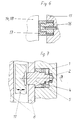
- Fig. 7 it is shown that the tapered pin 5 of the center positioning system is formed with a bearing journal. This is guided in a bearing bore in the resilient taper bush.
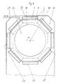
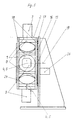
- FIGs 3, 4 and 5 is the device for feeding and presenting the one each Workpiece loaded and covered clamping pallets shown.
- the support body 14 is pivotable on one side about the horizontally virtual axis 19 in partial steps stored, connected to the carrying wall 15 with one end face, on the stand of the drilling-milling machining center, not shown, flanged.
- the service station manufacturing 21 In the tool for the drilling-milling machining center directed vertical center position on the support body 14 is the service station manufacturing 21.
- the service station 20 workpiece loading, workpiece clamping, checking the clamping state, Workpiece relaxation and unloading is in the upper horizontal position of the Clamping pallet on the support body 14, in the direction of rotation of the rotary drive 26 in front of the service station 21.
- the control of the carrying device, in particular the functional sequence on the service station 20, is coordinates with the automatic workpiece feed device 27, not shown in detail.
- Opposite service station 21, production is in the vertical middle position Clamping pallet on the support body 14, the service station 23, pivoting of the workpiece 9 in one more of the four processing positions.
- In the lower horizontal position of the Clamping pallet on the support body 14 is the service station 22, cleaning and relaxation of Clamping pallet and workpiece.
- the fittings required for the service stations, Mounts and positioning stops which are arranged or held on the carrying wall 15.
- the frontal arrangement and connection of the clamping pallets on the support body 14 is by two, attached to the face, fixed support rings 18 stabilized.
- the virtual axis 19 of the support body 14 which can be pivoted in partial steps is as a circular circumferential guide rail 16 arranged on the vertical support wall 15 of the guide shoes 17, which face the end faces of the clamping pallets, are formed.
- the support body 14 is from a motorized swivel drive, in Circular arc along the guide rail 16, movable.
- the circular circumferential guide rail 16 is positioned, screwed, and potted with adhesive on the ring surfaces in a wider ring groove, lying against the support wall 15.
Landscapes
- Engineering & Computer Science (AREA)
- Mechanical Engineering (AREA)
- Jigs For Machine Tools (AREA)
- Automobile Manufacture Line, Endless Track Vehicle, Trailer (AREA)
- Feeding Of Workpieces (AREA)
Abstract
Description
Beispielsweise beinhaltet das DE-Patent 4331166 einen Aufspannkörper als Grundkörper einer Spannvorrichtung, der aus senkrechten, dünnwandigen und biegesteifen Platten, in überlappender Verbindung angeordnet oder aus Säulen-Anordnungen strukturiert ist. Vorteilhaft ist, daß der Anteil des für Werkstück-Spannmittel und Werkstücke zur Verfügung stehende Arbeitsraum über der Spannpalette auf 80 bis 90 % erhöht ist.
Bei Nutzung derartig strukturierter Spannvorrichtungen ist in einer Spannlage nur eine Zwei- oder Dreiseitenbearbeitung auf dem Bearbeitungszentrum möglich. Für die Bearbeitung der zwei bis drei anderen Seiten an den Werkstücken ist eine Umspannung der Spannvorrichtung auf der Be- und Entladestation außerhalb des Arbeitsraumes am Bearbeitungszentrum oder eine weitere Spannvorrichtung für diese zusätzliche Spannlage der Werkstücke erforderlich.
- raumsparenden, einfach und kostengünstig ausgebildeten, Einrichtung zum Präsentieren des Werkstückes am Maschinenwerkzeug in günstig entspänender Stellung
- Lage- und Funktions-Koordinierung der Werkstückspannvorrichtungen mit einer Tragevorrichtung, auf der jeweils ein dimensionsoptimiertes Werkstück nicht nur die Station spanender Fertigung, sondern auch die vor- und nachbereitenden Servicestationen raumnah und bedienerfreundlich absolviert
- vereinfachten und für einen automatisierten Ablauf einschließlich automatischer Werkstückzu- und abfuhr geeigneter Baugruppen für Werkstückspannung und Werkstückhandling.
- raumsparenden, einfachen Elementeausbildung für die Mittenzentrierung, die Schwenkbeweglichkeit und der Festpositionierung der adaptiven Spannplatte an einer Trägerplatte
- zweckmäßigen Strukturierung der Trägerplatte als multifunktionelle Basisplatte der adaptiven Spannplatte
- leichtgewichtigen Spannpaletten-Strukturierung
- stabilisierenden und drehbeweglichen Ausbildung des aus Spannpaletten gebildeten Tragekörpers
- funktionsoptimierten Anordnung des Tragekörpers am Bohr-Fräs-Bearbeitungszentrum
- zweckmäßige Strukturierung der Spannfläche und der Spannmittel für das Werkstück an der adaptiven Spannplatte
- Fig. 1
- eine Ansicht einer Spannpalette im Mittenschnitt
- Fig. 2
- eine Seitenansicht der Spannpalette, von rechts, nach Fig. 1
- Fig. 3 und Fig. 4
- eine Ansicht des Trägerkörpers mit Spannpaletten, vereinfacht dargestellt
- Fig. 5
- eine Seitenansicht der Tragevorrichtung nach Fig. 3
- Fig. 6
- eine Ausschnittdarstellung von Führungsschuh und Führungsschiene
- Fig. 7
- eine Ausschnittdarstellung der Mittenzentrierung in der Spannpalette
Durch Betätigung der Hub- und Absenkelemente 12 erfolgt ein Anheben der Spannplatte 1 von der Trägerplatte 8 und ein axialgerichtetes Entkoppeln des Mittenpositioniersystems, womit die Schwenkbewegung der Spannplatte 1 einstell- und bestimmbar ist.
Nach Fig. 6 ist die kreisförmig umlaufende Führungsschiene 16 in ein breiter dimensionierten Ringnut, an der Tragewand 15 anliegend, positioniert, verschraubt und an den Ringflächen mit Kleber vergossen.
- 1
- Obere adaptive Spannplatte der Spannpalette
- 2
- Spannfläche
- 3
- Ringnut
- 4
- federnde Kegelbuchse
- 5
- Kegelbolzen
- 6
- Richt-/Indexbolzen
- 7
- Indexbuchsen
- 8
- untere Trägerplatte der Spannpalette
- 9
- Werkstück
- 10
- Linearantrieb
- 11
- Kraft- und Bewegungsübertragungselement
- 12
- Hub- und Absenkelemente
- 13
- Klemmhaken
- 14
- Tragekörper
- 15
- Tragewand
- 16
- Führungsschiene
- 17
- Führungsschuhe
- 18
- Tragringe des Tragekörpers
- 19
- virtuelle Achse des Tragekörpers
- 20
- Servicestation
- 21
- Servicestation
- 22
- Servicestation
- 23
- Servicestation
- 24
- Abdeckung
- 25
- Schwenkkreis
- 26
- Zahnradantrieb
- 27
- automatische Werkstückzuführ-Einrichtung
Claims (10)
- Adaptives Werkstück-Spann- und Handlingssystem zum Zuführen und Präsentieren von, auf adaptiven und schwenkachsbeweglichen Vorrichtungen, gespannten Werkstücken für die Fertigung in Bohr- und Fräs-Bearbeitungszentren, wobei fertigungsvor- und nachbereitende Servicestationen integriert sind,
dadurch gekennzeichnet, daß Spannvorrichtungen, auf deren Spannflächen (2) in Mittenlage je ein Werkstück (9) gespannt ist, im wesentlichen aus einer Spannpalette bestehen, wobei eine obere adaptive Spannplatte (1) um eine Mittenachse beliebig gerichtete, gegenüber einer unteren Trägerplatte (8) schwenkbeweglich, in Teilschritten positionierbar, ausgebildet ist, und
daß eine bestimmte Anzahl Spannpaletten, in endloser Reihe stirnseitig aneinanderliegend, die Spannflächen (2) umfänglich nach außen gerichtet und einem vieleckigen hohlen Tragekörper (14) bildend, miteinander verbunden sind und einseitig, um eine waagerechte virtuelle Achse schwenkbeweglich, in Teilschritten positionierbar, an einer senkrechten Tragewand (15) fest angeordnet sind,
wobei die virtuale Achse (19) als an einer Tragewand (15) kreisförmig umlaufende Führungsschiene (16) auf der, an der Tragewand (15) zugewandten, Stirnseiten der Spannpaletten angeordneten Führungsschuhe (17) abrollen und
die Schwenkbewegungs-Mittenachsen der adaptiven Spannpalette (1) in der Bearbeitungsstellung und des Tragekörpers (14) für Spannpaletten waagerecht lagekoordiniert zueinander in Abhängigkeit zur Werkzeugachse des Bearbeitungszentrums angeordnet sind, und
daß stellungsabhängig am Tragekörper (14) in der oberen, in waagerechter Stellung der Spannpaletten, koordiniert mit einer automatischen Werkstückzuführeinrichtung (27) die Servicestation (20), Werkstückbe- und entladung, Werkstückspannung und -entspannung sowie Kontrolle des Spannzustandes in der mittleren, senkrechten, zum Werkzeug gerichteten, Stellung der Spannpaletten die Servicestation Fertigung (21), in der unteren, waagerechten, Stellung der Spannpaletten die Servicestation (23), Schwenkung des Werkstückes in eine weitere Bearbeitungsstellung, zugeordnet sind und
die Armaturen, Halterungen und Positionieranschläge an der Tragewand (15) angeordnet sind. - Adaptives Werkstückspann- und Handlingssystem nach Patentanspruch 1,
dadurch gekennzeichnet, daß die
obere adaptive Spannplatte (1) der Spannpalette als eine kreisförmige Scheibe ausgebildet ist, an deren rückseitiger Kontaktfläche eine federnde Kegelbuchse (4) in der Mittenlage und in den Winkelstellungen in einem Kreisbogen um die Mittenlage mehrere Indexbuchsen (7) für einen Richt-/Indexbolzen (6) und auf der vorderseitigen Spannfläche (2) Öffnungen für Befestigungs-und Positionierelemente des Werkstückes (9) angeordnet sind. - Adaptives Werkstückspann- und Handlingssystem nach Patentanspruch 1,
dadurch gekennzeichnet, daß die
untere Trägerplatte (8) der Spannpalette als ein Hohlkörper ausgebildet ist, an dem der öldruck-und/oder federkraftbetätigte Linearantrieb (10) ein Kraft- und Bewegungsübertragungselement (11), ein Kegelbolzen (5), in Mittenlage linear angetriebene Richt-/Indexbolzen (6) und die Hub- und Absenkelemente (12) für die adaptive Spannplatte (1) angeordnet, und
an der Trägerplatte (8), die in die Ringnut (3) der Spannplatte (1) ragend, diese ver- und entriegelnde Klemmhaken (13) aufgenommen sind. - Adaptives Werkstück-Spann- und Handlingssystem nach Patentanspruch 1,
dadurch gekennzeichnet, daß die obere adaptive Spannplatte (1) der Spannpalette und der Tragekörper (14), mit den Spannpaletten mittels Zahnradtriebes (26), von motorischen Schwenk-Antrieben mit Drehgebern aus betätigt, schwenkbeweglich ausgebildet sind. - Adaptives Werkstück-Spann- und Handlingssystem nach Patentanspruch 1,
dadurch gekennzeichnet, daß die obere adaptive Spannplatte (1) eine Verbundscheibe, aus einem unteren, einem Zahnkranz des zahnradtriebtragenden Stahl-Teil und einem oberen Leichtmetall-Teil, auf dessen Spannfläche (2) Leicht-Werkstücke positioniert und gespannt sind, bestehend, ist. - Adaptives Werkstück-Spann- und Handlingssystem nach Patentanspruch 1,
dadurch gekennzeichnet, daß die, einen vieleckigen hohen Tragkörper (14) bildende, endlose Reihe aneinander liegender Spannpaletten an beiden Stirnseiten mit Tragringen (18) miteinander verbunden sind. - Adaptives Werkstück-Spann- und Handlingssystem nach Patentanspruch 1,
dadurch gekennzeichnet, daß die senkrechte Tragewand (15) lageabhängig zum Maschinen-Werkzeug am Ständer des Bearbeitungszentrums angeflanscht oder als Teil eines Gestells mit Bodenplatte ausgebildet ist. - Adaptives Werkstück-Spann- und Handlingssystem nach Patentanspruch 1,
dadurch gekennzeichnet, daß die kreisförmig umlaufende Führungsschiene (16) in einer breiter dimensionierten Ringnut der Tragewand (15) einliegend positioniert, verschraubt und an den Ringflächen mit Kleber vergossen ist. - Adaptives Werkstück-Spann- und Handlingssystem nach Patentanspruch 1,
dadurch gekennzeichnet, daß die Spannfläche (2) der oberen adaptiven Spannplatte (1) der Spannpalette mit einem Raster von T-Nuten gleichen Abstands und gleicher Breite oder mit öldruck- und/oder federkraftbetätigten Spannelementen ausgestattet ist. - Adaptives Werkstück-Spann- und Handlingssystem nach Patentanspruch 1,
dadurch gekennzeichnet, daß die Öffnungen des hohlen Tragekörpers (14) und der Servicestationen späneabweisend mit einer Abdeckung (24) verschlossen sind.
Applications Claiming Priority (2)
| Application Number | Priority Date | Filing Date | Title |
|---|---|---|---|
| DE10013975A DE10013975C2 (de) | 2000-03-21 | 2000-03-21 | Adaptives Werkstück-Spann- und Handlingssystem |
| DE10013975 | 2000-03-21 |
Publications (3)
| Publication Number | Publication Date |
|---|---|
| EP1136179A2 true EP1136179A2 (de) | 2001-09-26 |
| EP1136179A3 EP1136179A3 (de) | 2002-11-13 |
| EP1136179B1 EP1136179B1 (de) | 2004-01-14 |
Family
ID=7635768
Family Applications (1)
| Application Number | Title | Priority Date | Filing Date |
|---|---|---|---|
| EP01250096A Expired - Lifetime EP1136179B1 (de) | 2000-03-21 | 2001-03-16 | Adaptives Werkstück-Spann- und Handlingssystem |
Country Status (3)
| Country | Link |
|---|---|
| EP (1) | EP1136179B1 (de) |
| AT (1) | ATE257758T1 (de) |
| DE (2) | DE10013975C2 (de) |
Cited By (21)
| Publication number | Priority date | Publication date | Assignee | Title |
|---|---|---|---|---|
| CN104624594A (zh) * | 2015-02-03 | 2015-05-20 | 成都大漠石油机械有限公司 | 固定环内径可调节的钻杆固定机构 |
| CN106736624A (zh) * | 2016-12-28 | 2017-05-31 | 宾科汽车紧固件(昆山)有限公司 | 一种油管接头加工装置及其加工方法 |
| CN108500244A (zh) * | 2018-04-17 | 2018-09-07 | 安徽永茂泰汽车零部件有限公司 | 立式多功能圆盘铣浇口机 |
| CN108995394A (zh) * | 2018-07-12 | 2018-12-14 | 蚌埠市瑞泰汽配制造有限公司 | 一种滤清器壳体喷码加工的定位工装 |
| CN110561300A (zh) * | 2019-09-12 | 2019-12-13 | 安徽飞马电缆有限公司 | 一种电缆检测用定位夹具 |
| CN111673154A (zh) * | 2020-06-15 | 2020-09-18 | 杭州具彩网络科技有限公司 | 一种用于钳子头内外两面异形牙型连续铣削加工的机构 |
| CN111982053A (zh) * | 2020-09-13 | 2020-11-24 | 濮阳职业技术学院 | 一种基于电气自动化控制的工程操作台及其控制方法 |
| CN112621275A (zh) * | 2020-12-28 | 2021-04-09 | 山西双环重工集团有限公司 | 对中夹紧机构及环件加工设备 |
| CN113927330A (zh) * | 2021-10-18 | 2022-01-14 | 重庆嘉陵特种装备有限公司 | 一种安装工件的工装夹具 |
| CN114043396A (zh) * | 2021-12-09 | 2022-02-15 | 浙江海洋大学 | 一种异形工件机械加工固定装置 |
| US20220187783A1 (en) * | 2019-04-08 | 2022-06-16 | Proquadro S.r.L. | Numerical control tool machine |
| CN114871903A (zh) * | 2022-03-11 | 2022-08-09 | 恒强铝业股份有限公司 | 一种铝合金门窗加工辅助设备 |
| CN115533784A (zh) * | 2022-10-11 | 2022-12-30 | 河北安迪模具有限公司 | 玻璃器皿模具加工专用工装夹具 |
| CN115741180A (zh) * | 2022-12-09 | 2023-03-07 | 无锡瑞真精机股份有限公司 | 气门桥摆臂加工用夹具 |
| CN115990725A (zh) * | 2021-10-20 | 2023-04-21 | 上海荥科制冷设备有限公司 | 一种环缝焊机 |
| CN117139143A (zh) * | 2023-10-31 | 2023-12-01 | 康硕(山西)智能制造有限公司 | 一种用于3d打印的金属粉末制造筛分装置 |
| CN118559555A (zh) * | 2024-06-28 | 2024-08-30 | 江苏弗曼机械设备有限公司 | 一种光学玻璃片打磨用自适应抱紧夹持装置 |
| CN119857797A (zh) * | 2025-03-24 | 2025-04-22 | 佛山市华韵机械有限公司 | 一种具有自动送料功能的铝条冲孔设备 |
| CN120170668A (zh) * | 2025-05-21 | 2025-06-20 | 台州市洛克赛工具有限公司 | 一种风扳寿命测试快速换装夹具 |
| CN120572482A (zh) * | 2025-08-05 | 2025-09-02 | 江东金具设备有限公司 | 管母用支撑装置 |
| CN120800204A (zh) * | 2025-07-30 | 2025-10-17 | 苏州思苾特精工技术有限公司 | 一种电机壳体尺寸激光测量装置及方法 |
Families Citing this family (6)
| Publication number | Priority date | Publication date | Assignee | Title |
|---|---|---|---|---|
| DE10238372A1 (de) * | 2002-08-22 | 2004-03-11 | Brinkmann, Johannes, Dipl.-Ing. | Vorrichtung zum Aufspannen von Werkstücken sowie Verfahren zum Bearbeiten von zwei Werkstücken in der Vorrichtung |
| DE102004002859A1 (de) * | 2004-01-19 | 2005-08-18 | Fertigungstechnik Weissenfels Gmbh | Vorrichtung zum Schwenken von Werkstücken oder Vorrichtung in Bearbeitungsmaschinen |
| DE202009002638U1 (de) | 2009-02-23 | 2009-05-28 | Hohenstein Vorrichtungsbau Und Spannsysteme Gmbh | Schwenkmodul-Kombination für Werkstücke |
| DE102010052676B4 (de) | 2010-11-25 | 2013-07-25 | Hohenstein Vorrichtungsbau Und Spannsysteme Gmbh | Verfahren zur Werkstück-Positionierung und -Fixierung |
| CN108080957B (zh) * | 2018-01-26 | 2024-05-24 | 永嘉县正菱机械科技股份有限公司 | 万向节叉钻耳孔设备 |
| CN112658709A (zh) * | 2020-12-09 | 2021-04-16 | 中国第一汽车股份有限公司 | 一种零部件圆弧结构加工工装及加工方法 |
Family Cites Families (4)
| Publication number | Priority date | Publication date | Assignee | Title |
|---|---|---|---|---|
| DE8603558U1 (de) * | 1986-02-11 | 1987-02-05 | Bernhard Steinel Werkzeugmaschinenfabrik GmbH u. Co, 78056 Villingen-Schwenningen | Palettenspeicher für ein Bearbeitungszentrum |
| DE3643329C2 (de) * | 1986-12-18 | 1996-02-22 | Ravensburg Maschf | Palettenwechselsystem |
| DE4320501C2 (de) * | 1993-06-21 | 1995-09-07 | Sim Zufuehr Und Montagetechnik | Anlage für die Bearbeitung und/oder Montage von auf einem Werkstückträger angeordneten Werkstücken |
| DE4331166C2 (de) * | 1993-09-14 | 1998-11-19 | Hohenstein Vorrichtungsbau | Aufspannkörper einer Spannpalette |
-
2000
- 2000-03-21 DE DE10013975A patent/DE10013975C2/de not_active Expired - Fee Related
-
2001
- 2001-03-16 EP EP01250096A patent/EP1136179B1/de not_active Expired - Lifetime
- 2001-03-16 AT AT01250096T patent/ATE257758T1/de active
- 2001-03-16 DE DE50101306T patent/DE50101306D1/de not_active Expired - Lifetime
Cited By (26)
| Publication number | Priority date | Publication date | Assignee | Title |
|---|---|---|---|---|
| CN104624594A (zh) * | 2015-02-03 | 2015-05-20 | 成都大漠石油机械有限公司 | 固定环内径可调节的钻杆固定机构 |
| CN106736624A (zh) * | 2016-12-28 | 2017-05-31 | 宾科汽车紧固件(昆山)有限公司 | 一种油管接头加工装置及其加工方法 |
| CN108500244A (zh) * | 2018-04-17 | 2018-09-07 | 安徽永茂泰汽车零部件有限公司 | 立式多功能圆盘铣浇口机 |
| CN108500244B (zh) * | 2018-04-17 | 2023-10-17 | 安徽永茂泰汽车零部件有限公司 | 立式多功能圆盘铣浇口机 |
| CN108995394A (zh) * | 2018-07-12 | 2018-12-14 | 蚌埠市瑞泰汽配制造有限公司 | 一种滤清器壳体喷码加工的定位工装 |
| US20220187783A1 (en) * | 2019-04-08 | 2022-06-16 | Proquadro S.r.L. | Numerical control tool machine |
| US12128518B2 (en) * | 2019-04-08 | 2024-10-29 | TECNO LOGICA S.r.l. | Numerical control tool machine |
| CN110561300A (zh) * | 2019-09-12 | 2019-12-13 | 安徽飞马电缆有限公司 | 一种电缆检测用定位夹具 |
| CN111673154A (zh) * | 2020-06-15 | 2020-09-18 | 杭州具彩网络科技有限公司 | 一种用于钳子头内外两面异形牙型连续铣削加工的机构 |
| CN111982053A (zh) * | 2020-09-13 | 2020-11-24 | 濮阳职业技术学院 | 一种基于电气自动化控制的工程操作台及其控制方法 |
| CN112621275A (zh) * | 2020-12-28 | 2021-04-09 | 山西双环重工集团有限公司 | 对中夹紧机构及环件加工设备 |
| CN113927330A (zh) * | 2021-10-18 | 2022-01-14 | 重庆嘉陵特种装备有限公司 | 一种安装工件的工装夹具 |
| CN115990725A (zh) * | 2021-10-20 | 2023-04-21 | 上海荥科制冷设备有限公司 | 一种环缝焊机 |
| CN114043396A (zh) * | 2021-12-09 | 2022-02-15 | 浙江海洋大学 | 一种异形工件机械加工固定装置 |
| CN114871903A (zh) * | 2022-03-11 | 2022-08-09 | 恒强铝业股份有限公司 | 一种铝合金门窗加工辅助设备 |
| CN114871903B (zh) * | 2022-03-11 | 2023-08-29 | 恒强铝业股份有限公司 | 一种铝合金门窗加工辅助设备 |
| CN115533784A (zh) * | 2022-10-11 | 2022-12-30 | 河北安迪模具有限公司 | 玻璃器皿模具加工专用工装夹具 |
| CN115533784B (zh) * | 2022-10-11 | 2023-06-13 | 河北安迪模具有限公司 | 玻璃器皿模具加工专用工装夹具 |
| CN115741180A (zh) * | 2022-12-09 | 2023-03-07 | 无锡瑞真精机股份有限公司 | 气门桥摆臂加工用夹具 |
| CN117139143A (zh) * | 2023-10-31 | 2023-12-01 | 康硕(山西)智能制造有限公司 | 一种用于3d打印的金属粉末制造筛分装置 |
| CN117139143B (zh) * | 2023-10-31 | 2024-03-08 | 康硕(山西)智能制造有限公司 | 一种用于3d打印的金属粉末制造筛分装置 |
| CN118559555A (zh) * | 2024-06-28 | 2024-08-30 | 江苏弗曼机械设备有限公司 | 一种光学玻璃片打磨用自适应抱紧夹持装置 |
| CN119857797A (zh) * | 2025-03-24 | 2025-04-22 | 佛山市华韵机械有限公司 | 一种具有自动送料功能的铝条冲孔设备 |
| CN120170668A (zh) * | 2025-05-21 | 2025-06-20 | 台州市洛克赛工具有限公司 | 一种风扳寿命测试快速换装夹具 |
| CN120800204A (zh) * | 2025-07-30 | 2025-10-17 | 苏州思苾特精工技术有限公司 | 一种电机壳体尺寸激光测量装置及方法 |
| CN120572482A (zh) * | 2025-08-05 | 2025-09-02 | 江东金具设备有限公司 | 管母用支撑装置 |
Also Published As
| Publication number | Publication date |
|---|---|
| DE10013975A1 (de) | 2001-10-04 |
| DE10013975C2 (de) | 2002-01-31 |
| EP1136179B1 (de) | 2004-01-14 |
| DE50101306D1 (de) | 2004-02-19 |
| EP1136179A3 (de) | 2002-11-13 |
| ATE257758T1 (de) | 2004-01-15 |
Similar Documents
| Publication | Publication Date | Title |
|---|---|---|
| EP1136179A2 (de) | Adaptives Werkstück-Spann- und Handlingssystem | |
| DE3110221C2 (de) | Revolverstanzpresse | |
| DE69907283T2 (de) | Maschine zum bohren von öllöchern in kurbelwellen und dessen methode | |
| EP0139857B1 (de) | Roboteranlagen | |
| EP0739672A2 (de) | Spannvorrichtung zum umfangsseitigen Spannen von Werkstücken mit beliebiger Umfangskontur | |
| DE4315839C2 (de) | Werkstückspannvorrichtung für Mehrseitenbearbeitung | |
| DE19614641A1 (de) | Vorrichtung zur Bearbeitung und Montage von Werkstücken | |
| EP0157728A1 (de) | Drehmaschine | |
| DE102005042179B4 (de) | Flexible Fertigungszelle für die Bearbeitung von Bauteilen, insbesondere von Fahrzeugkarosserien | |
| DE4032881A1 (de) | Verfahren und vorrichtung zum einspannen eines werkstuecks | |
| DE19800034C2 (de) | Werkzeugmaschine für Bearbeitungswerkzeuge aus der Gruppe Schleifkörper und Fräser | |
| DE19716797A1 (de) | Lagerichtige Ein-Nippel-Einspannung | |
| DE1627042B2 (de) | Vorrichtung mit einem indexierbaren werkstuecktraeger und mit einem diesen foerdernden foerderring an einer ringtransfermaschine | |
| DE2462088C2 (de) | Halter für Tiefziehmatrizen | |
| EP0019654A1 (de) | Revolver für Drehmaschine | |
| DE102018105481A1 (de) | Montageeinrichtung und Montageverfahren | |
| DE2129515C3 (de) | Schalttellermaschine | |
| DE69412045T2 (de) | Halter für Teile, insbesondere für eine Bearbeitungsstation mit einem Drehtisch | |
| DE3441968A1 (de) | Gegenstandsfeststeller, -aufspannvorrichtung und bearbeitungsverfahren | |
| DE202004018168U1 (de) | Aus einer Spannvorrichtung und einem Werkstückträger gebildete Einheit | |
| EP0236379B1 (de) | Vorrichtung zum wechseln von werkzeugen bei schleifoperationen | |
| DE2811357A1 (de) | Einrichtung zum automatischen werkzeugwechsel an mehrspindelbohrmaschinen | |
| EP1125869B1 (de) | Montagevorrichtung | |
| EP0261261A1 (de) | Bearbeitungsmaschine | |
| DE3416171A1 (de) | Palettentraeger fuer werkzeugmaschine |
Legal Events
| Date | Code | Title | Description |
|---|---|---|---|
| PUAI | Public reference made under article 153(3) epc to a published international application that has entered the european phase |
Free format text: ORIGINAL CODE: 0009012 |
|
| AK | Designated contracting states |
Kind code of ref document: A2 Designated state(s): AT BE CH CY DE DK ES FI FR GB GR IE IT LI LU MC NL PT SE TR |
|
| AX | Request for extension of the european patent |
Free format text: AL;LT;LV;MK;RO;SI |
|
| PUAL | Search report despatched |
Free format text: ORIGINAL CODE: 0009013 |
|
| 17P | Request for examination filed |
Effective date: 20020822 |
|
| AK | Designated contracting states |
Kind code of ref document: A3 Designated state(s): AT BE CH CY DE DK ES FI FR GB GR IE IT LI LU MC NL PT SE TR |
|
| AX | Request for extension of the european patent |
Free format text: AL;LT;LV;MK;RO;SI |
|
| RIC1 | Information provided on ipc code assigned before grant |
Free format text: 7B 23Q 39/04 A, 7B 23Q 16/06 B, 7B 23Q 7/14 B, 7B 23Q 7/02 B |
|
| GRAP | Despatch of communication of intention to grant a patent |
Free format text: ORIGINAL CODE: EPIDOSNIGR1 |
|
| AKX | Designation fees paid |
Designated state(s): AT CH DE FR GB LI |
|
| GRAS | Grant fee paid |
Free format text: ORIGINAL CODE: EPIDOSNIGR3 |
|
| GRAA | (expected) grant |
Free format text: ORIGINAL CODE: 0009210 |
|
| AK | Designated contracting states |
Kind code of ref document: B1 Designated state(s): AT CH DE FR GB LI |
|
| REG | Reference to a national code |
Ref country code: GB Ref legal event code: FG4D Free format text: NOT ENGLISH |
|
| REG | Reference to a national code |
Ref country code: CH Ref legal event code: EP |
|
| REG | Reference to a national code |
Ref country code: IE Ref legal event code: FG4D Free format text: GERMAN |
|
| REF | Corresponds to: |
Ref document number: 50101306 Country of ref document: DE Date of ref document: 20040219 Kind code of ref document: P |
|
| GBT | Gb: translation of ep patent filed (gb section 77(6)(a)/1977) |
Effective date: 20040322 |
|
| REG | Reference to a national code |
Ref country code: IE Ref legal event code: FD4D |
|
| ET | Fr: translation filed | ||
| PLBE | No opposition filed within time limit |
Free format text: ORIGINAL CODE: 0009261 |
|
| STAA | Information on the status of an ep patent application or granted ep patent |
Free format text: STATUS: NO OPPOSITION FILED WITHIN TIME LIMIT |
|
| 26N | No opposition filed |
Effective date: 20041015 |
|
| PGFP | Annual fee paid to national office [announced via postgrant information from national office to epo] |
Ref country code: AT Payment date: 20110310 Year of fee payment: 11 Ref country code: FR Payment date: 20110318 Year of fee payment: 11 |
|
| PGFP | Annual fee paid to national office [announced via postgrant information from national office to epo] |
Ref country code: GB Payment date: 20120328 Year of fee payment: 12 |
|
| REG | Reference to a national code |
Ref country code: AT Ref legal event code: MM01 Ref document number: 257758 Country of ref document: AT Kind code of ref document: T Effective date: 20120316 |
|
| REG | Reference to a national code |
Ref country code: FR Ref legal event code: ST Effective date: 20121130 |
|
| PG25 | Lapsed in a contracting state [announced via postgrant information from national office to epo] |
Ref country code: AT Free format text: LAPSE BECAUSE OF NON-PAYMENT OF DUE FEES Effective date: 20120316 Ref country code: FR Free format text: LAPSE BECAUSE OF NON-PAYMENT OF DUE FEES Effective date: 20120402 |
|
| GBPC | Gb: european patent ceased through non-payment of renewal fee |
Effective date: 20130316 |
|
| PG25 | Lapsed in a contracting state [announced via postgrant information from national office to epo] |
Ref country code: GB Free format text: LAPSE BECAUSE OF NON-PAYMENT OF DUE FEES Effective date: 20130316 |
|
| PGFP | Annual fee paid to national office [announced via postgrant information from national office to epo] |
Ref country code: DE Payment date: 20140829 Year of fee payment: 14 Ref country code: CH Payment date: 20140902 Year of fee payment: 14 |
|
| REG | Reference to a national code |
Ref country code: DE Ref legal event code: R081 Ref document number: 50101306 Country of ref document: DE Owner name: WVL-WERKZEUG- UND VORRICHTUNGSBAU LICHTENSTEIN, DE Free format text: FORMER OWNER: HOHENSTEIN VORRICHTUNGSBAU UND SPANNSYSTEME GMBH, 09337 HOHENSTEIN-ERNSTTHAL, DE Effective date: 20141119 |
|
| REG | Reference to a national code |
Ref country code: DE Ref legal event code: R119 Ref document number: 50101306 Country of ref document: DE |
|
| REG | Reference to a national code |
Ref country code: CH Ref legal event code: PL |
|
| PG25 | Lapsed in a contracting state [announced via postgrant information from national office to epo] |
Ref country code: CH Free format text: LAPSE BECAUSE OF NON-PAYMENT OF DUE FEES Effective date: 20150331 Ref country code: LI Free format text: LAPSE BECAUSE OF NON-PAYMENT OF DUE FEES Effective date: 20150331 Ref country code: DE Free format text: LAPSE BECAUSE OF NON-PAYMENT OF DUE FEES Effective date: 20151001 |