EP1136668A1 - Méthode et dispositif pour purifier les gaz d'échappement - Google Patents
Méthode et dispositif pour purifier les gaz d'échappement Download PDFInfo
- Publication number
- EP1136668A1 EP1136668A1 EP01105188A EP01105188A EP1136668A1 EP 1136668 A1 EP1136668 A1 EP 1136668A1 EP 01105188 A EP01105188 A EP 01105188A EP 01105188 A EP01105188 A EP 01105188A EP 1136668 A1 EP1136668 A1 EP 1136668A1
- Authority
- EP
- European Patent Office
- Prior art keywords
- catalyst
- exhaust gas
- gas discharge
- gas
- electrical
- Prior art date
- Legal status (The legal status is an assumption and is not a legal conclusion. Google has not performed a legal analysis and makes no representation as to the accuracy of the status listed.)
- Granted
Links
Images

Classifications
-
- F—MECHANICAL ENGINEERING; LIGHTING; HEATING; WEAPONS; BLASTING
- F01—MACHINES OR ENGINES IN GENERAL; ENGINE PLANTS IN GENERAL; STEAM ENGINES
- F01N—GAS-FLOW SILENCERS OR EXHAUST APPARATUS FOR MACHINES OR ENGINES IN GENERAL; GAS-FLOW SILENCERS OR EXHAUST APPARATUS FOR INTERNAL-COMBUSTION ENGINES
- F01N3/00—Exhaust or silencing apparatus having means for purifying, rendering innocuous, or otherwise treating exhaust
- F01N3/08—Exhaust or silencing apparatus having means for purifying, rendering innocuous, or otherwise treating exhaust for rendering innocuous
- F01N3/0892—Electric or magnetic treatment, e.g. dissociation of noxious components
-
- B—PERFORMING OPERATIONS; TRANSPORTING
- B01—PHYSICAL OR CHEMICAL PROCESSES OR APPARATUS IN GENERAL
- B01D—SEPARATION
- B01D53/00—Separation of gases or vapours; Recovering vapours of volatile solvents from gases; Chemical or biological purification of waste gases, e.g. engine exhaust gases, smoke, fumes, flue gases, aerosols
- B01D53/34—Chemical or biological purification of waste gases
- B01D53/92—Chemical or biological purification of waste gases of engine exhaust gases
- B01D53/94—Chemical or biological purification of waste gases of engine exhaust gases by catalytic processes
- B01D53/944—Simultaneously removing carbon monoxide, hydrocarbons or carbon making use of oxidation catalysts
-
- F—MECHANICAL ENGINEERING; LIGHTING; HEATING; WEAPONS; BLASTING
- F01—MACHINES OR ENGINES IN GENERAL; ENGINE PLANTS IN GENERAL; STEAM ENGINES
- F01N—GAS-FLOW SILENCERS OR EXHAUST APPARATUS FOR MACHINES OR ENGINES IN GENERAL; GAS-FLOW SILENCERS OR EXHAUST APPARATUS FOR INTERNAL-COMBUSTION ENGINES
- F01N3/00—Exhaust or silencing apparatus having means for purifying, rendering innocuous, or otherwise treating exhaust
- F01N3/08—Exhaust or silencing apparatus having means for purifying, rendering innocuous, or otherwise treating exhaust for rendering innocuous
- F01N3/10—Exhaust or silencing apparatus having means for purifying, rendering innocuous, or otherwise treating exhaust for rendering innocuous by thermal or catalytic conversion of noxious components of exhaust
- F01N3/24—Exhaust or silencing apparatus having means for purifying, rendering innocuous, or otherwise treating exhaust for rendering innocuous by thermal or catalytic conversion of noxious components of exhaust characterised by constructional aspects of converting apparatus
- F01N3/28—Construction of catalytic reactors
- F01N3/2882—Catalytic reactors combined or associated with other devices, e.g. exhaust silencers or other exhaust purification devices
-
- B—PERFORMING OPERATIONS; TRANSPORTING
- B01—PHYSICAL OR CHEMICAL PROCESSES OR APPARATUS IN GENERAL
- B01D—SEPARATION
- B01D2259/00—Type of treatment
- B01D2259/80—Employing electric, magnetic, electromagnetic or wave energy, or particle radiation
- B01D2259/818—Employing electrical discharges or the generation of a plasma
-
- F—MECHANICAL ENGINEERING; LIGHTING; HEATING; WEAPONS; BLASTING
- F01—MACHINES OR ENGINES IN GENERAL; ENGINE PLANTS IN GENERAL; STEAM ENGINES
- F01N—GAS-FLOW SILENCERS OR EXHAUST APPARATUS FOR MACHINES OR ENGINES IN GENERAL; GAS-FLOW SILENCERS OR EXHAUST APPARATUS FOR INTERNAL-COMBUSTION ENGINES
- F01N2240/00—Combination or association of two or more different exhaust treating devices, or of at least one such device with an auxiliary device, not covered by indexing codes F01N2230/00 or F01N2250/00, one of the devices being
- F01N2240/04—Combination or association of two or more different exhaust treating devices, or of at least one such device with an auxiliary device, not covered by indexing codes F01N2230/00 or F01N2250/00, one of the devices being an electric, e.g. electrostatic, device other than a heater
-
- F—MECHANICAL ENGINEERING; LIGHTING; HEATING; WEAPONS; BLASTING
- F01—MACHINES OR ENGINES IN GENERAL; ENGINE PLANTS IN GENERAL; STEAM ENGINES
- F01N—GAS-FLOW SILENCERS OR EXHAUST APPARATUS FOR MACHINES OR ENGINES IN GENERAL; GAS-FLOW SILENCERS OR EXHAUST APPARATUS FOR INTERNAL-COMBUSTION ENGINES
- F01N2240/00—Combination or association of two or more different exhaust treating devices, or of at least one such device with an auxiliary device, not covered by indexing codes F01N2230/00 or F01N2250/00, one of the devices being
- F01N2240/28—Combination or association of two or more different exhaust treating devices, or of at least one such device with an auxiliary device, not covered by indexing codes F01N2230/00 or F01N2250/00, one of the devices being a plasma reactor
Definitions
- the invention relates to a method with the Features of the preamble of claim 1.
- Catalysts are used to improve their heating behavior located as close as possible to the exhaust manifold of the engine, which, however, lead to thermal problems at full load can.
- electrical heaters were used or burners with a few kilowatts of heating power, which by supplying thermal energy the exhaust gas before the Heat the catalyst additionally.
- the invention is therefore based on the object of a method with the procedural steps of the preamble of the claim 1 to improve so that pollutant degradation favorable influenced and the onset of catalytic action as possible is accelerated.
- This task is accomplished by a method with the characteristics of the characterizing part of claim 1 solved.
- the plasma module is used upstream of the catalyst. This is done in view of the fact that the present one Method, as in the known method, one for effective combination of plasma chemical degradation Processes in the plasma module and the catalytic processes in the catalytic converter takes place. In particular, an effect is achieved that more than a summation of the effect of the plasma on the one hand and the effect of the catalyst on the other hand.
- the plasma module and arrange the catalyst so that the unstably excited Gas molecules from the plasma module get into the catalyst can before entering stable states or in reaction products fall.
- the optimization of pollutant degradation described above is achieved with a plasma module in which a barrier discharge triggers oxidative reactions that are part of the Break down pollutants. Arises during the operation of the plasma module Long-lived oxidative radicals in the barrier discharge and reactive partially oxidized pollutant products that with the Gas flow from the plasma module in the practically immediately adjacent Catalyst are worn.
- the parameters electrical gas discharge, e.g. corresponding the DE 196 26 381 C2 is switched on intermittently, so chosen that as large a part of the reactions as possible is completed after using the edited solid the exhaust gas has flowed into the catalytic converter.
- the one in such Volume element contained unstable excited gas molecules are radicals like atomic oxygen or nitrogen, metastable ozone or reaction products of those contained in the exhaust gas Substances water, carbon dioxide, carbon monoxide, nitrogen oxides, Hydrocarbons or particles. Electronic excitation states occur or ions on, but also vibratory or rotational excitation states.
- the radicals come in the catalyst with the existing catalytically active surfaces through impacts to reaction. They heat up as a result the chemical exothermic on the catalyst.
- the stoichiometric or exhaust gas from the rich operation of the internal combustion engine used oxidizing being an electrical gas discharge subjected and in contact with a catalytic material brought.
- a plasma module and a catalyst there is no one Distance between a plasma module and a catalyst, who should be particularly attuned to the fact that unstable excited gas molecules with the exhaust gas from the plasma module in flow the catalyst.
- the method can be carried out accordingly advantageously be that generated by the gas discharge unstable excited gas molecules in contact with the catalytic material come.
- the process can be carried out as unstable excited gas molecules chemical radicals of the oxygen-containing Exhaust gas, its decomposition or reaction products be used in the catalyst, as described above has been. It is important that also in the decomposition products resulting from electrical gas discharge and / or reaction products of the exhaust gas can be used. These are multi-atomic compounds or Particles that do not instantly decompose completely in the plasma were gradually degraded in reaction chains. For example, hydrogen abstraction often occurs. The resulting intermediates at least reach Part of the catalyst surface. It is important that these substances in the catalyst even at lower temperatures can respond because they have less stability have as their unexcited starting molecules. So far finds an interaction between the plasma module and the catalyst instead of.
- the procedure is advantageously such that the gas discharge up to ten seconds before and at the latest with the start the internal combustion engine is switched on.
- the rapid heating of the catalyst through the gas discharge according to the above-described method is advantageous together used with the usual measures, such as a close to the engine Arrangement of the catalyst and a secondary air injection. Because the immediate gas discharge even when completely ineffective Catalyst breaks down pollutants through the process pollution reduction in every operating state of the engine be achieved.
- the method can also be carried out so that the Gas discharge during engine operation when falling below one predetermined catalyst temperature for a limited Time is switched on. This is particularly useful if the engine is operating for a longer period with a low partial load Time goes through, so that as a result a reduction in Temperature of the catalyst takes place at which the complete or predetermined degradation of the pollutants no longer guaranteed is.
- the procedure can then be such that a catalyst temperature below 150 ° C the duty cycle of the plasma module is greater than 50%.
- the range of 250 ° C up to 300 ° C results in a with today's materials significant activity of catalysts, which prefer a process lets, at a catalyst temperature above 300 ° C the duty cycle of the plasma module is less than 20 % is.
- a comparable procedure can be followed in such a way that the gas discharge is switched on during engine operation, if an exhaust gas composition is determined that corresponds to the catalytic Pollutant degradation is detrimental. This avoids that the catalytic converter is malfunctioning, for example, due to deposited particles, the flow resistance increase in an unacceptable way and the effective Reduce total catalyst area.
- Another process variant is gas discharge to be switched on briefly when there are emission peaks during engine operation.
- emission peaks can, for example, during warming up the engine or during a load change of the engine occur in one operating state or before that the catalyst temperature either dropped is or a load occurs for which the catalyst is not designed.
- this makes it possible to Optimizing the design of the catalyst, for example in terms of its size and / or its service life.
- the process can be carried out so that the electrical Power of the gas discharge is chosen so that at an ambient temperature of 0 ° C and a relative humidity of 50% the time for heating the temperature of the catalyst at the catalyst inlet to 250 ° C in the MVEG test compared to an MVEG test without gas discharge to at least Is shortened by 80%.
- the electrical Power of the gas discharge is chosen so that at an ambient temperature of 0 ° C and a relative humidity of 50% the time for heating the temperature of the catalyst at the catalyst inlet to 250 ° C in the MVEG test compared to an MVEG test without gas discharge to at least Is shortened by 80%.
- the electrical power of the plasma module is not 800 watts exceeds and is preferably 200 to 500 watts.
- the method is advantageously carried out in such a way that that the performance of the gas discharge after reaching a predetermined Starting temperature for a predetermined time is withdrawn to zero. This makes it possible to Self-heating of the catalyst through pollutant degradation to use that he himself at a higher than the predetermined Warm-up temperature at which it reaches the predetermined Pollutant degradation without the participation of the plasma module can perform.
- the one arranged in the exhaust gas line of the internal combustion engine and reactor consisting of the module and the catalyst is located close to the engine to avoid heat loss and to minimize the light-off time of the catalyst. If a cold start is carried out with the vehicle, that is when a driver operates the starter, the following will Process steps from the engine control or other Control units causes: the ignition, the fuel supply, as well as the electrical supply to the plasma module are during the first engine revolution, namely as soon as a gas throughput occurs in the plasma module.
- the engine control acts in such a way that a high exhaust gas temperature is established.
- a secondary air pump can be switched on with regard to concentricity and / or wall desorption for operational reasons enrich rich exhaust gas with oxygen. A litigation can also be done so that the plasma module somewhat earlier or turned on a little later than the first engine revolution becomes.
- the electrical power when operating the plasma module should be chosen so that during the heating time a significant but not too large proportion of the catalyst is broken down. Because with a major breakdown in the raw exhaust gas existing pollutants, for example, decreases by over 50% the specific efficiency, that means the energy expenditure per molecule chemically degraded. An optimization of the electrical power is such that a significant reduction the light-off time of the catalyst results.
- the for Typical power required by conventional car engines is typically at a few hundred watts, well below that Performance required for an electrically heated catalytic converter is required.
- the during the turn-on time of the plasma module total energy consumed can also continue be minimized when the electrical power to the current Pollutant concentration and adapted to the exhaust gas volume flow becomes.
- the catalyst In a third phase, the catalyst finally has reaches its working temperature, and the gas discharge can can be switched off to save energy.
- the exact one Power history and the operating time of the discharge depends on the availability of energy from the battery or alternator and must with regard to fuel consumption and pollution reduction be optimized. Later also unsteady Operating phases of the engine are usually sufficient Power from the alternator available and through short-term Switching on the plasma reactor can possibly occur Emission peaks are intercepted. As required can also after a low partial load or Engine idling phase, the catalytic converter starts again be facilitated by switching on the plasma.
- the aforementioned Process steps achieved, the effect of the plasma module and to combine the catalyst. It follows an increase in the effectiveness of the process in the sense that the time until the onset of catalytic action, that is, the light-off time is reduced, as is the light-off temperature, that is, the temperature at which the catalytic Effect.
- the procedure can be in the aforementioned Senses can be further optimized. Such optimization will achieved in that the electrical gas discharge in the sense an unstable excitation of a predetermined proportion of Hydrocarbon molecules is carried out.
- the above-mentioned process is based on the knowledge that, in particular, an unstable excitation of hydrocarbon molecules leads to an optimization of the overall process for cleaning exhaust gas.
- the electrical gas discharge has such an influence on the proportion of hydrocarbon molecules in the exhaust gas that a substantial direct degradation already takes place at the time when the barrier discharge begins, for example to about half the raw concentration.
- concentration of hydrocarbons this means C 3 H 8 equivalent determined by conventional processes, such as flame ionization, in which the various hydrocarbon molecules which occur are weighted roughly according to the number of carbon atoms contained.
- the procedure is such that the predetermined proportion is less than 70% of the total hydrocarbons of the exhaust gas. It is therefore sufficient to break down less than 70% of the total hydrocarbons in the exhaust gas with the electric gas discharge in order to achieve a residual breakdown to practically zero with the catalyst. If only some of the hydrocarbons are now degraded during plasma-chemical degradation, then on the one hand some molecules may have been completely oxidized to CO 2 and H 2 O and on the other hand molecules may also have been partially oxidized, ie converted into other hydrocarbon molecules. Saturated hydrocarbons (paraffins) thus become olefins and aromatics with a higher C / H ratio or oxygen-containing aldehydes, alcohols, ethers and ketones.
- paraffins paraffins
- the method can advantageously be carried out in this way be that the electrical gas discharge in the sense of a breakdown a predetermined proportion of pollutants is carried out, being a high proportion of unstable molecules from incomplete Decomposition is formed. As a result, it is possible break down only a predetermined proportion of all pollutants, in such a way that a high proportion becomes unstable Results in molecules.
- predetermining the proportion of pollutants can the process in terms of optimization according to the above task be performed.
- the method in this way can be advantageous to do the method in this way perform that the electrical gas discharge a high Proportion of such hydrocarbon molecules and radicals in the exhaust gas generates a lower light off temperature for one have catalytic conversion, as carbon monoxide or as the rest of the exhaust gas.
- the Hydrocarbons instead of the above for hydrocarbons refine generally described optimization.
- the invention also relates to a device for Cleaning exhaust gas, especially exhaust gas from internal combustion engines, with an exhaust line in which the exhaust gas of an electrical Plasma module subjected to gas discharge and a catalyst are present in which the exhaust gas is in contact with catalytic Material arrives.
- a device for Cleaning exhaust gas especially exhaust gas from internal combustion engines, with an exhaust line in which the exhaust gas of an electrical Plasma module subjected to gas discharge and a catalyst are present in which the exhaust gas is in contact with catalytic Material arrives.
- a device is out known from DE 196 26 381 C2 and apply to the device basically the disadvantages described above for this.
- the known plasma module is arranged after the catalyst. So it is certainly not a combination effect possible in the sense that effects of the plasma module positive would have influence on the catalyst operation.
- the device is therefore in the sense of the task set out above going to perfect that the plasma module in the exhaust line is arranged upstream of the catalyst.
- the plasma module precedes the catalyst at a distance that allows that gas molecules unstably excited by the gas discharge get into the catalyst. In this case arrive unstably excited gas molecules before the end of their reaction time in the catalytic converter, where they act on the catalytic React exothermic surfaces. It is surprisingly done a faster reaching of the light-off temperature of the Catalyst than by electrical heating with the same Performance and thus an unexpected improvement in one Degradation of pollutants in the exhaust gas.
- the device can be designed so that the catalyst a honeycomb coated with precious metal has ceramic carrier.
- a commercial, e.g. coated with platinum or other precious metals Catalyst are used with which the plasma module cooperates.
- Proven catalyst technology leads to the fact that the required catalytic effect can be guaranteed, but at the same time one from this catalyst and one plasma module generated reactor is inexpensive to manufacture.
- a further improvement of the device results in that the plasma module and the catalyst one as Represented unit trained reactor in the exhaust line is located close to the engine.
- the arrangement of the reactor close to the engine ensures optimal utilization of the Exhaust gas temperature. Construction and assembly effort kept small because the plasma module and catalytic converter are one unit form. Accordingly, the space requirement is also small.
- the plasma module 3 is on an electrical ballast 31 connected, if necessary one required to create a barrier discharge high frequency high voltage generated.
- the ballast 31 gets its power from the on-board network of a motor vehicle, depending on the state of charge of the battery and the current engine power from the alternator, the battery or both.
- the ballast has interfaces to one central control unit, for example the engine control, from which it can be turned on and off instantly and from which the electrical power can also be regulated as required can.
- Fig. 2a shows schematically the course of the electrical Power P over time t for the operation of the electrical Gas discharge.
- 2b shows the course of the temperature T im Area of the catalyst over time t.
- 2c shows schematically the course of pollutant concentrations above the Time t.
- a predetermined electrical power P E for operating the electrical gas discharge is switched on and maintained until time t1.
- the electrical power is then reduced to zero by time t2.
- the temperature T would follow the course of the lower curve. After a time t0 would the light-off temperature T0 of the catalyst 4 can be reached. The catalyst would act accordingly and because of the exothermic conversion in the catalyst a steeper temperature rise respectively. A pollutant concentration c0 would be from Time t0 decrease as shown in Fig. 2c.
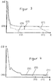
- a catalytic converter If a catalytic converter is used, after it has been heated up by the exhaust gas at a specific point in time 11 or t 0 , it will exceed a light-off temperature T 0 .
- the catalytic effect that then begins has the effect that the concentration of the hydrocarbons HC and the concentration of the carbon monoxide CO are reduced to zero in accordance with the courses 21 and 31 shown.
- the aim was to use a combined process that is, an unstable excitation of a predetermined proportion of hydrocarbon molecules using electrical Gas discharge and catalytic cleaning, influence on the start time a catalyst for the degradation of pollutants to take.
- Carbon monoxide CO starts at 13 according to the course 33 to zero, while HC to one earlier point in time 12 assumes the value zero according to curve 23. After time 13 the gas discharge is no longer required, to completely break down the pollutants.
- the catalyst does not yet have the one without Plasma required light-off temperature reached. Behind the The catalyst therefore becomes a significant CO concentration measured. Also, the catalyst would be in the event of a shutdown of the plasma is not active, i.e.
- hydrocarbons would be issued again. In this second phase you can the electrical power for gas discharge, however, already be reduced. Because the heating of the catalyst nevertheless proceeds due to the heat input from the hot exhaust gas from the engine and due to the heat of reaction during pollutant degradation away. Any the electrical gas discharge between the If times 12 and 13 are switched off, there would be a further increase of hydrocarbon HC to the value 20 of the raw concentration, i.e. like with the catalyst alone.
- a plasma module to generate a barrier discharge is used, as is a catalyst with a honeycomb-shaped ceramic carrier coated with precious metal.
- the plasma module is upstream of the catalyst and both are so close to each other, that unstably excited gas molecules from the plasma module flow into the catalytic converter with the exhaust gas do not lose their excitation state outside the catalyst, but only in cooperation with components of the catalyst.
Landscapes
- Chemical & Material Sciences (AREA)
- Engineering & Computer Science (AREA)
- Chemical Kinetics & Catalysis (AREA)
- Combustion & Propulsion (AREA)
- Health & Medical Sciences (AREA)
- Mechanical Engineering (AREA)
- Toxicology (AREA)
- General Engineering & Computer Science (AREA)
- Biomedical Technology (AREA)
- Environmental & Geological Engineering (AREA)
- Analytical Chemistry (AREA)
- General Chemical & Material Sciences (AREA)
- Oil, Petroleum & Natural Gas (AREA)
- Exhaust Gas After Treatment (AREA)
- Exhaust Gas Treatment By Means Of Catalyst (AREA)
Applications Claiming Priority (4)
| Application Number | Priority Date | Filing Date | Title |
|---|---|---|---|
| DE10009731 | 2000-03-02 | ||
| DE2000109731 DE10009731A1 (de) | 2000-03-02 | 2000-03-02 | Verfahren zum Reinigen von Abgas |
| DE10009730 | 2000-03-02 | ||
| DE2000109730 DE10009730A1 (de) | 2000-03-02 | 2000-03-02 | Verfahren und Vorrichtung zum Reinigen von Abgas |
Publications (2)
| Publication Number | Publication Date |
|---|---|
| EP1136668A1 true EP1136668A1 (fr) | 2001-09-26 |
| EP1136668B1 EP1136668B1 (fr) | 2004-05-19 |
Family
ID=26004596
Family Applications (1)
| Application Number | Title | Priority Date | Filing Date |
|---|---|---|---|
| EP20010105188 Expired - Lifetime EP1136668B1 (fr) | 2000-03-02 | 2001-03-02 | Méthode et dispositif pour purifier les gaz d'échappement |
Country Status (1)
| Country | Link |
|---|---|
| EP (1) | EP1136668B1 (fr) |
Cited By (4)
| Publication number | Priority date | Publication date | Assignee | Title |
|---|---|---|---|---|
| RU2216389C1 (ru) * | 2002-08-06 | 2003-11-20 | Суровин Вячеслав Константинович | Нейтрализатор |
| RU2230602C1 (ru) * | 2003-02-03 | 2004-06-20 | Суровин Вячеслав Константинович | Нейтрализатор автомагистральный |
| RU2361095C1 (ru) * | 2007-12-18 | 2009-07-10 | Федеральное государственное унитарное предприятие "Московское машиностроительное производственное предприятие "САЛЮТ" (ФГУП "ММПП "САЛЮТ") | Устройство для очистки отработавших газов двигателя внутреннего сгорания от оксидов азота |
| EP2728133A4 (fr) * | 2011-06-30 | 2015-04-08 | Imagineering Inc | Dispositif de production de plasma |
Citations (9)
| Publication number | Priority date | Publication date | Assignee | Title |
|---|---|---|---|---|
| US4780277A (en) * | 1985-05-10 | 1988-10-25 | Shinryo Corporation | Method and apparatus for subjecting gases to discharge treatment |
| JPH0598956A (ja) * | 1991-05-24 | 1993-04-20 | Hitachi Ltd | 排気浄化システムと浄化方法及びそれを用いた自動車 |
| JPH05332128A (ja) * | 1992-05-27 | 1993-12-14 | Nagatoshi Suzuki | 排気ガス浄化装置 |
| EP0585047A2 (fr) * | 1992-08-27 | 1994-03-02 | United Kingdom Atomic Energy Authority | La purification des émissions de gaz d'échappement de moteurs à combustion interne |
| US5310461A (en) * | 1989-11-21 | 1994-05-10 | H.R.S. Engineering S.R.L. | Cold oxidation in gaseous phase |
| JPH07247827A (ja) * | 1994-03-14 | 1995-09-26 | Isuzu Motors Ltd | 内燃機関の排ガス浄化装置 |
| DE19510804A1 (de) * | 1995-03-24 | 1996-09-26 | Dornier Gmbh | Verfahren und Vorrichtung zur Stickoxidminderung in Abgasen von Verbrennungsmaschinen |
| US5711147A (en) * | 1996-08-19 | 1998-01-27 | The Regents Of The University Of California | Plasma-assisted catalytic reduction system |
| DE19645689A1 (de) * | 1996-11-06 | 1998-05-07 | Bayerische Motoren Werke Ag | Vorrichtung zur Abgasnachbehandlung für eine Brennkraftmaschine, insbesondere Otto-Motor mit Magerbetrieb |
-
2001
- 2001-03-02 EP EP20010105188 patent/EP1136668B1/fr not_active Expired - Lifetime
Patent Citations (9)
| Publication number | Priority date | Publication date | Assignee | Title |
|---|---|---|---|---|
| US4780277A (en) * | 1985-05-10 | 1988-10-25 | Shinryo Corporation | Method and apparatus for subjecting gases to discharge treatment |
| US5310461A (en) * | 1989-11-21 | 1994-05-10 | H.R.S. Engineering S.R.L. | Cold oxidation in gaseous phase |
| JPH0598956A (ja) * | 1991-05-24 | 1993-04-20 | Hitachi Ltd | 排気浄化システムと浄化方法及びそれを用いた自動車 |
| JPH05332128A (ja) * | 1992-05-27 | 1993-12-14 | Nagatoshi Suzuki | 排気ガス浄化装置 |
| EP0585047A2 (fr) * | 1992-08-27 | 1994-03-02 | United Kingdom Atomic Energy Authority | La purification des émissions de gaz d'échappement de moteurs à combustion interne |
| JPH07247827A (ja) * | 1994-03-14 | 1995-09-26 | Isuzu Motors Ltd | 内燃機関の排ガス浄化装置 |
| DE19510804A1 (de) * | 1995-03-24 | 1996-09-26 | Dornier Gmbh | Verfahren und Vorrichtung zur Stickoxidminderung in Abgasen von Verbrennungsmaschinen |
| US5711147A (en) * | 1996-08-19 | 1998-01-27 | The Regents Of The University Of California | Plasma-assisted catalytic reduction system |
| DE19645689A1 (de) * | 1996-11-06 | 1998-05-07 | Bayerische Motoren Werke Ag | Vorrichtung zur Abgasnachbehandlung für eine Brennkraftmaschine, insbesondere Otto-Motor mit Magerbetrieb |
Non-Patent Citations (3)
| Title |
|---|
| PATENT ABSTRACTS OF JAPAN vol. 017, no. 443 (M - 1463) 16 August 1993 (1993-08-16) * |
| PATENT ABSTRACTS OF JAPAN vol. 018, no. 164 (M - 1579) 18 March 1994 (1994-03-18) * |
| PATENT ABSTRACTS OF JAPAN vol. 1996, no. 01 31 January 1996 (1996-01-31) * |
Cited By (4)
| Publication number | Priority date | Publication date | Assignee | Title |
|---|---|---|---|---|
| RU2216389C1 (ru) * | 2002-08-06 | 2003-11-20 | Суровин Вячеслав Константинович | Нейтрализатор |
| RU2230602C1 (ru) * | 2003-02-03 | 2004-06-20 | Суровин Вячеслав Константинович | Нейтрализатор автомагистральный |
| RU2361095C1 (ru) * | 2007-12-18 | 2009-07-10 | Федеральное государственное унитарное предприятие "Московское машиностроительное производственное предприятие "САЛЮТ" (ФГУП "ММПП "САЛЮТ") | Устройство для очистки отработавших газов двигателя внутреннего сгорания от оксидов азота |
| EP2728133A4 (fr) * | 2011-06-30 | 2015-04-08 | Imagineering Inc | Dispositif de production de plasma |
Also Published As
| Publication number | Publication date |
|---|---|
| EP1136668B1 (fr) | 2004-05-19 |
Similar Documents
| Publication | Publication Date | Title |
|---|---|---|
| DE69911242T2 (de) | Selektive katalytische reduktion system und verfahren | |
| EP0988104B1 (fr) | Procede et dispositif pour eliminer des polluants de type oxyde dans un gaz d'echappement contenant de l'oxygene et moteur fonctionnant de fa on correspondante | |
| DE69126143T2 (de) | Katalytischer reaktor und verfahren zur emissionsbegrenzung | |
| EP1023935B1 (fr) | Procédé pour la reduction catalytique sélective des oxydes d'azote dans des gaz d'échappement contenant de l'oxygène | |
| DE112004002324B4 (de) | Verfahren zum Reduzieren von NOx in Dieselmotorenabgas | |
| DE69904623T2 (de) | Anordnung und verfahren zur reinigung von abgasen | |
| DE602005005921T2 (de) | Abgasreinigungsanlage und Verfahren zur Steuerung | |
| EP1425497B1 (fr) | Dispositif et procede de post-traitement de gaz d'echappement | |
| EP0953375B1 (fr) | Procédé pour dimineur le taux d'oxydes d'azote dans des gaz d'échappement d'un moteur à combustion | |
| WO2001083087A1 (fr) | Procede et dispositif d'epuration de gaz d'echappement | |
| EP1567753A1 (fr) | Vehicule automobile a moteur d'entrainement diesel | |
| DE60007037T3 (de) | Vorrichtung und Verfahren zur Behandlung von Partikeln und Stickoxyden für eine Brennkraftmaschine | |
| DE102008015722A1 (de) | Abgasreinigungsvorrichtung | |
| WO1996037690A1 (fr) | Procede et dispositif pour traiter des gaz d'echappement | |
| DE4209198C1 (fr) | ||
| EP1020620A1 (fr) | Dispositif d'épuration des gaz d'échappement d'un moteur a combustion interne | |
| EP1136668B1 (fr) | Méthode et dispositif pour purifier les gaz d'échappement | |
| EP1304455B1 (fr) | Filtre à particules pour la purification de gaz d'échappement de moteurs | |
| DE102006043087A1 (de) | Verfahren und Vorrichtung zur Aufheizung eines Reduktionsmittel-Generierungssystems | |
| EP0910730B1 (fr) | PROCEDE ET DISPOSITIF POUR FAIRE FONCTIONNER DE FAçON PEU POLLUANTE UN MOTEUR A COMBUSTION INTERNE | |
| DE60223186T2 (de) | Behandlungssystem für Abgas und dessen Verwendung | |
| EP1026373A2 (fr) | Dispositif de purification des gaz d'échappement d'un moteur à combustion interne | |
| DE19645689B4 (de) | Vorrichtung zur Abgasnachbehandlung für eine Brennkraftmaschine, insbesondere Otto-Motor mit Magerbetrieb | |
| WO2001006106A1 (fr) | Procede et dispositif pour la desulfatation d'un catalyseur accumulateur de no¿x? | |
| DE4231575C2 (de) | Verfahren und Vorrichtung zur Steuerung einer Brennkraftmaschine |
Legal Events
| Date | Code | Title | Description |
|---|---|---|---|
| PUAI | Public reference made under article 153(3) epc to a published international application that has entered the european phase |
Free format text: ORIGINAL CODE: 0009012 |
|
| AK | Designated contracting states |
Kind code of ref document: A1 Designated state(s): AT BE CH CY DE DK ES FI FR GB GR IE IT LI LU MC NL PT SE TR Kind code of ref document: A1 Designated state(s): DE FR GB IT |
|
| AX | Request for extension of the european patent |
Free format text: AL;LT;LV;MK;RO;SI |
|
| 17P | Request for examination filed |
Effective date: 20011213 |
|
| 17Q | First examination report despatched |
Effective date: 20020123 |
|
| AKX | Designation fees paid |
Free format text: DE FR GB IT |
|
| GRAP | Despatch of communication of intention to grant a patent |
Free format text: ORIGINAL CODE: EPIDOSNIGR1 |
|
| RAP1 | Party data changed (applicant data changed or rights of an application transferred) |
Owner name: VOLKSWAGEN AG Owner name: FRAUNHOFER-GESELLSCHAFT ZUR FOERDERUNG DERANGEWAND |
|
| GRAS | Grant fee paid |
Free format text: ORIGINAL CODE: EPIDOSNIGR3 |
|
| GRAA | (expected) grant |
Free format text: ORIGINAL CODE: 0009210 |
|
| AK | Designated contracting states |
Kind code of ref document: B1 Designated state(s): DE FR GB IT |
|
| PG25 | Lapsed in a contracting state [announced via postgrant information from national office to epo] |
Ref country code: IT Free format text: LAPSE BECAUSE OF FAILURE TO SUBMIT A TRANSLATION OF THE DESCRIPTION OR TO PAY THE FEE WITHIN THE PRESCRIBED TIME-LIMIT;WARNING: LAPSES OF ITALIAN PATENTS WITH EFFECTIVE DATE BEFORE 2007 MAY HAVE OCCURRED AT ANY TIME BEFORE 2007. THE CORRECT EFFECTIVE DATE MAY BE DIFFERENT FROM THE ONE RECORDED. Effective date: 20040519 Ref country code: GB Free format text: LAPSE BECAUSE OF FAILURE TO SUBMIT A TRANSLATION OF THE DESCRIPTION OR TO PAY THE FEE WITHIN THE PRESCRIBED TIME-LIMIT Effective date: 20040519 |
|
| REG | Reference to a national code |
Ref country code: GB Ref legal event code: FG4D Free format text: NOT ENGLISH |
|
| REF | Corresponds to: |
Ref document number: 50102304 Country of ref document: DE Date of ref document: 20040624 Kind code of ref document: P |
|
| GBV | Gb: ep patent (uk) treated as always having been void in accordance with gb section 77(7)/1977 [no translation filed] |
Effective date: 20040519 |
|
| ET | Fr: translation filed | ||
| PLBE | No opposition filed within time limit |
Free format text: ORIGINAL CODE: 0009261 |
|
| STAA | Information on the status of an ep patent application or granted ep patent |
Free format text: STATUS: NO OPPOSITION FILED WITHIN TIME LIMIT |
|
| 26N | No opposition filed |
Effective date: 20050222 |
|
| PGFP | Annual fee paid to national office [announced via postgrant information from national office to epo] |
Ref country code: FR Payment date: 20090330 Year of fee payment: 9 |
|
| REG | Reference to a national code |
Ref country code: FR Ref legal event code: ST Effective date: 20101130 |
|
| PG25 | Lapsed in a contracting state [announced via postgrant information from national office to epo] |
Ref country code: FR Free format text: LAPSE BECAUSE OF NON-PAYMENT OF DUE FEES Effective date: 20100331 |
|
| PGFP | Annual fee paid to national office [announced via postgrant information from national office to epo] |
Ref country code: DE Payment date: 20150324 Year of fee payment: 15 |
|
| REG | Reference to a national code |
Ref country code: DE Ref legal event code: R119 Ref document number: 50102304 Country of ref document: DE |
|
| PG25 | Lapsed in a contracting state [announced via postgrant information from national office to epo] |
Ref country code: DE Free format text: LAPSE BECAUSE OF NON-PAYMENT OF DUE FEES Effective date: 20161001 |