EP1136674A2 - Dispositif d'admission avec des tube de suralimentation par inertie et avec des tubes de résonance à longueur variable - Google Patents
Dispositif d'admission avec des tube de suralimentation par inertie et avec des tubes de résonance à longueur variable Download PDFInfo
- Publication number
- EP1136674A2 EP1136674A2 EP01105204A EP01105204A EP1136674A2 EP 1136674 A2 EP1136674 A2 EP 1136674A2 EP 01105204 A EP01105204 A EP 01105204A EP 01105204 A EP01105204 A EP 01105204A EP 1136674 A2 EP1136674 A2 EP 1136674A2
- Authority
- EP
- European Patent Office
- Prior art keywords
- resonance
- channels
- housing
- suction device
- collectors
- Prior art date
- Legal status (The legal status is an assumption and is not a legal conclusion. Google has not performed a legal analysis and makes no representation as to the accuracy of the status listed.)
- Granted
Links
- 238000002485 combustion reaction Methods 0.000 claims description 18
- 230000010355 oscillation Effects 0.000 claims description 5
- 230000000694 effects Effects 0.000 description 9
- 238000005192 partition Methods 0.000 description 5
- 230000006978 adaptation Effects 0.000 description 2
- 230000000875 corresponding effect Effects 0.000 description 2
- 238000009434 installation Methods 0.000 description 2
- 230000010354 integration Effects 0.000 description 2
- 238000007789 sealing Methods 0.000 description 2
- 238000010276 construction Methods 0.000 description 1
- 238000011161 development Methods 0.000 description 1
- 230000018109 developmental process Effects 0.000 description 1
- 230000002349 favourable effect Effects 0.000 description 1
- 238000004519 manufacturing process Methods 0.000 description 1
- 230000001360 synchronised effect Effects 0.000 description 1
- 238000011144 upstream manufacturing Methods 0.000 description 1
Images


Classifications
-
- F—MECHANICAL ENGINEERING; LIGHTING; HEATING; WEAPONS; BLASTING
- F02—COMBUSTION ENGINES; HOT-GAS OR COMBUSTION-PRODUCT ENGINE PLANTS
- F02B—INTERNAL-COMBUSTION PISTON ENGINES; COMBUSTION ENGINES IN GENERAL
- F02B27/00—Use of kinetic or wave energy of charge in induction systems, or of combustion residues in exhaust systems, for improving quantity of charge or for increasing removal of combustion residues
- F02B27/02—Use of kinetic or wave energy of charge in induction systems, or of combustion residues in exhaust systems, for improving quantity of charge or for increasing removal of combustion residues the systems having variable, i.e. adjustable, cross-sectional areas, chambers of variable volume, or like variable means
- F02B27/0226—Use of kinetic or wave energy of charge in induction systems, or of combustion residues in exhaust systems, for improving quantity of charge or for increasing removal of combustion residues the systems having variable, i.e. adjustable, cross-sectional areas, chambers of variable volume, or like variable means characterised by the means generating the charging effect
- F02B27/0247—Plenum chambers; Resonance chambers or resonance pipes
- F02B27/0257—Rotatable plenum chambers
-
- F—MECHANICAL ENGINEERING; LIGHTING; HEATING; WEAPONS; BLASTING
- F02—COMBUSTION ENGINES; HOT-GAS OR COMBUSTION-PRODUCT ENGINE PLANTS
- F02B—INTERNAL-COMBUSTION PISTON ENGINES; COMBUSTION ENGINES IN GENERAL
- F02B27/00—Use of kinetic or wave energy of charge in induction systems, or of combustion residues in exhaust systems, for improving quantity of charge or for increasing removal of combustion residues
- F02B27/02—Use of kinetic or wave energy of charge in induction systems, or of combustion residues in exhaust systems, for improving quantity of charge or for increasing removal of combustion residues the systems having variable, i.e. adjustable, cross-sectional areas, chambers of variable volume, or like variable means
-
- F—MECHANICAL ENGINEERING; LIGHTING; HEATING; WEAPONS; BLASTING
- F02—COMBUSTION ENGINES; HOT-GAS OR COMBUSTION-PRODUCT ENGINE PLANTS
- F02B—INTERNAL-COMBUSTION PISTON ENGINES; COMBUSTION ENGINES IN GENERAL
- F02B27/00—Use of kinetic or wave energy of charge in induction systems, or of combustion residues in exhaust systems, for improving quantity of charge or for increasing removal of combustion residues
- F02B27/02—Use of kinetic or wave energy of charge in induction systems, or of combustion residues in exhaust systems, for improving quantity of charge or for increasing removal of combustion residues the systems having variable, i.e. adjustable, cross-sectional areas, chambers of variable volume, or like variable means
- F02B27/0205—Use of kinetic or wave energy of charge in induction systems, or of combustion residues in exhaust systems, for improving quantity of charge or for increasing removal of combustion residues the systems having variable, i.e. adjustable, cross-sectional areas, chambers of variable volume, or like variable means characterised by the charging effect
- F02B27/0215—Oscillating pipe charging, i.e. variable intake pipe length charging
- F02B27/0221—Resonance charging combined with oscillating pipe charging
-
- F—MECHANICAL ENGINEERING; LIGHTING; HEATING; WEAPONS; BLASTING
- F02—COMBUSTION ENGINES; HOT-GAS OR COMBUSTION-PRODUCT ENGINE PLANTS
- F02B—INTERNAL-COMBUSTION PISTON ENGINES; COMBUSTION ENGINES IN GENERAL
- F02B27/00—Use of kinetic or wave energy of charge in induction systems, or of combustion residues in exhaust systems, for improving quantity of charge or for increasing removal of combustion residues
- F02B27/02—Use of kinetic or wave energy of charge in induction systems, or of combustion residues in exhaust systems, for improving quantity of charge or for increasing removal of combustion residues the systems having variable, i.e. adjustable, cross-sectional areas, chambers of variable volume, or like variable means
- F02B27/0226—Use of kinetic or wave energy of charge in induction systems, or of combustion residues in exhaust systems, for improving quantity of charge or for increasing removal of combustion residues the systems having variable, i.e. adjustable, cross-sectional areas, chambers of variable volume, or like variable means characterised by the means generating the charging effect
- F02B27/0247—Plenum chambers; Resonance chambers or resonance pipes
- F02B27/0252—Multiple plenum chambers or plenum chambers having inner separation walls, e.g. comprising valves for the same group of cylinders
-
- F—MECHANICAL ENGINEERING; LIGHTING; HEATING; WEAPONS; BLASTING
- F02—COMBUSTION ENGINES; HOT-GAS OR COMBUSTION-PRODUCT ENGINE PLANTS
- F02B—INTERNAL-COMBUSTION PISTON ENGINES; COMBUSTION ENGINES IN GENERAL
- F02B27/00—Use of kinetic or wave energy of charge in induction systems, or of combustion residues in exhaust systems, for improving quantity of charge or for increasing removal of combustion residues
- F02B27/02—Use of kinetic or wave energy of charge in induction systems, or of combustion residues in exhaust systems, for improving quantity of charge or for increasing removal of combustion residues the systems having variable, i.e. adjustable, cross-sectional areas, chambers of variable volume, or like variable means
- F02B27/0226—Use of kinetic or wave energy of charge in induction systems, or of combustion residues in exhaust systems, for improving quantity of charge or for increasing removal of combustion residues the systems having variable, i.e. adjustable, cross-sectional areas, chambers of variable volume, or like variable means characterised by the means generating the charging effect
- F02B27/0247—Plenum chambers; Resonance chambers or resonance pipes
- F02B27/0263—Plenum chambers; Resonance chambers or resonance pipes the plenum chamber and at least one of the intake ducts having a common wall, and the intake ducts wrap partially around the plenum chamber, i.e. snail-type
-
- Y—GENERAL TAGGING OF NEW TECHNOLOGICAL DEVELOPMENTS; GENERAL TAGGING OF CROSS-SECTIONAL TECHNOLOGIES SPANNING OVER SEVERAL SECTIONS OF THE IPC; TECHNICAL SUBJECTS COVERED BY FORMER USPC CROSS-REFERENCE ART COLLECTIONS [XRACs] AND DIGESTS
- Y02—TECHNOLOGIES OR APPLICATIONS FOR MITIGATION OR ADAPTATION AGAINST CLIMATE CHANGE
- Y02T—CLIMATE CHANGE MITIGATION TECHNOLOGIES RELATED TO TRANSPORTATION
- Y02T10/00—Road transport of goods or passengers
- Y02T10/10—Internal combustion engine [ICE] based vehicles
- Y02T10/12—Improving ICE efficiencies
Definitions
- the invention relates to a suction device, in particular a suction pipe for a Internal combustion engine, which one for the use of vibrating tube charging effects Vibrating collector with suction channels as vibrating tubes and for using effects the resonance charging length adjustable resonance channels and a resonance collector has, according to the preamble of claim 1. Also relates to Invention an actuator housing for accommodating the length-adjustable resonance pipes according to the preamble of claim 7.
- the resonance collector is housed in a hollow cylindrical roller 22 and with an inlet provided for the combustion air.
- the air enters through openings 8a, 8b Resonance channel 8, which is adjustable in length by rotation of the roller 22.
- the resonance channel opens into a vibration collector 6, through which the combustion air in Suction channels 2 arrives in a cylinder head flange 4 for connection to the Internal combustion engine open.
- Parallel to the vibration collector 6 is a vibration collector 7 arranged, which works analogously to the vibrating collector 6.
- Both Vibration collectors are in a manner not shown via a lockable channel connected with each other.
- This channel is closed by a resonance flap, the effect of resonance charging when the flap is closed and the effect when the flap is open Flap the effect of the oscillating tube charging of the internal combustion engine Combustion air can be used.
- the solution shown for the intake manifold is made very compact by the Housing areas of the resonance channels and the intake manifold, containing the vibration collectors 6, 7 and the suction channels 2, 3 are nested. Still needed the entire suction device due to the required minimum radii of channels flowed through by the combustion air a space that is shown in the Application of an internal combustion engine with a V-shaped cylinder arrangement in rare Cases is available.
- the suction device is characterized a considerable overall height, so that, provided the intake device is installed in the Internal combustion engine succeeds, the total height of which is difficult in the engine compartment of a vehicle is to be accommodated.
- the object of the invention is therefore to provide an intake system with suction channels and adjustable length To create resonance channels that optimally match the geometric Boundary conditions of the installation space can be adjusted. This task will solved by the features of claim 1 and 7.
- the suction device has length-adjustable resonance channels, that wind in a spiral around at least one resonance collector. It it is also possible for the resonance channels to be around two different resonance collectors winch, whereby the resonance collectors communicate with each other via a line need to ensure the effect of resonance charging.
- Acoustically effective volumes are thus defined in the sense of the invention.
- the acoustically effective connection between two resonance collectors counts strictly speaking to the volume that leads to the resonance effects.
- the length of the resonance channels is determined by rotating one or more actuators achieved, which are summarized in an actuator housing or in different Adjustment housings can be accommodated.
- the actuator contains in his central area the resonance collector, so that the connection opening between Resonance collector and resonance channels shifted by rotating the actuator can be, whereby the effective length of the resonance channels can be changed.
- the suction channels are to be assigned to two groups and lead accordingly Leaves in at least one cylinder head flange.
- a suction pipe is conceivable for an internal combustion engine with the cylinders arranged in series. Both are running here Groups of cylinders together in a cylinder head flange.
- the suction pipe can but also for an internal combustion engine with a V-arrangement of the cylinders, the groups of suction channels with the associated outlets each for one Cylinder bank are provided. Basically z. B. for an internal combustion engine with W-arrangement of the cylinders, the suction channels are divided into three different ones Groups conceivable.
- At least one resonance channel must be provided for each vibration collector. It However, several resonance channels can also be arranged, which means that the few Cross-sectional area for the resonance channels better match the geometric Boundary conditions of the suction device can be adjusted. By switching off Part of the resonance channels can be seen to reduce the overall Reach cross-sectional area of the resonance channels.
- the resonance flap between the vibrating collectors can either be arranged in a channel, which connects the different vibration collectors. Another possibility consists in an arrangement of the resonance flap in a partition between the swing collectors. This enables a greater degree of integration of the individual Reach volumes in a case structure.
- the control housing can also be in the housing structure of the suction device can be integrated.
- the invention is characterized by a connecting channel, which is between extends to the resonance channels and the vibration collectors and for bridging contributes to a spatial distance that exists between the vibration collectors and gives the substantially cylindrical volume of the control housing.
- the connection channels allow greater freedom of arrangement of the control housing. This allows the geometry of the intake manifold to be optimally matched to that provided Installation space can be adjusted.
- the connecting channels extend the length-adjustable resonance channels and have a corresponding effect of the resonance effect. In the construction of the suction device is therefore to the required length ratios and the required adjustment range by the Length adjustment.
- the connection channels can be used within these boundary conditions can be freely designed in their geometry.
- the suction device which are arranged side by side in a drum-shaped control housing.
- the air inlet is, for example, in the axis of rotation for the actuators, and the connecting channels close tangentially to the outer circumference of the control housing on, with a corresponding curvature of the connecting channels the air in the resonance channels is also redirected and to the appropriate inlets can be passed on in the vibration collectors.
- the resonance channels are around arranged around the resonance collector. This allows the connection channels be formed different lengths, which means the total length of the Resonance channels are the same length regardless of the position of the actuator. This gives the design freedom in the arrangement of the control housing in the Suction device further enlarged.
- This multi-chamber profile forms a separate one for each of the connecting channels Cross-section. Overall, it can be seen that certain wall parts of Every connection channel can be used to achieve material savings. In addition, when connecting the multi-chamber pipe to other housing structures the suction device assembly effort can be saved.
- control housing can be separated be carried out by an intake manifold housing, both housings together the suction device and in the intake manifold housing at least the vibration collectors and the suction channels are included.
- the connection between the intake manifold housing and control housing is guaranteed at least via the connecting channels.
- additional mounting devices can be provided which lead to a lead stiffer connection or facilitate assembly.
- the actuator housing executed individually, this can advantageously be used as a module, which is suitable for attachment to various suction pipes. So that can Adjusting housing can be adapted to different suction pipes, reducing the effort a new design is always only for the intake manifold housing. In this way series can be developed, including different engine variants Suction pipes can be equipped, which depending on the equipment with or without charging through resonance tubes.
- a further embodiment of the Invention can be designed at least partially as adapter pieces. This is one geometric adaptation to different intake manifold housings through use different adapter pieces possible.
- a particularly simple option is to attach the control housing on the throttle valve neck of the intake manifold housing.
- the throttle will then no longer at the intake manifold housing but at the combustion air inlet on Adjustment housing installed.
- This is also a retrofit for resonance charging of existing intake manifold concepts conceivable, which the affiliation a modular throttle valve on the intake manifold inlet provide.
- the principle of a suction device described at the beginning can be seen with reference to FIG with combined vibrating tube and resonance charging.
- the current the intake air is indicated by arrows.
- the intake air passes through a throttle valve 10 and flows into a resonance collector 11. From there it passes through adjustable length Resonance channels 12 in two vibrating collectors 13 through a resonance flap 14 are connected.
- Suction channels 15 go from the vibration collectors which are to be divided into two groups according to the vibration collector.
- Through the throttle valve neck is an inlet 16 and through a cylinder head flange 17 outlets 18 of the suction channels to the cylinder head are formed.
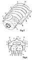
- an actuator housing 19 is shown, as in a suction device.
- Fig. 1 can be used.
- This consists of an essentially cylindrical Adjustment housing body 20, which is closed with a cover 21.
- Both Resonance channels 12 are formed by an actuating body 22, which consists of a Cylinder jacket 23 and a bearing cap 24 there.
- About journal 25 is the actuating body 22 is mounted in the actuating housing 19.
- Radial ribs 26 independently of intake air through the inlet 16 from the angular position of the adjusting body 22.
- the adjusting roller is replaced by a Drive 27 adjusted.
- the components of the resonance channel adjustment are assembled via screws 28.
- a seal of the moving components against the housing components takes place via sealing rings 29 which are supported radially in the housing.
- the resonance channels 12 will on the one hand by the outer sides of the control body 22 and on the other hand by a Inner contour 32 of the control housing is formed. They run helically around the Actuator around.
- an intake device which consists of an intake manifold housing 37, containing suction channels 15, two through a partition 38 with a resonance flap separate vibration collector 13, a cylinder head flange 17, and one separately executed control housing exists. These two housing parts are through an adapter piece 39, which serves as a connecting channel. there the control housing 20 is accommodated between the suction channels 15 in a space-saving manner.
- the actuating housing 20 also has the inlet 16, which acts as a flange for a Throttle valve is executed.
- the adapter piece 39 is provided with a throttle valve connector 40 connected, the above the partition 38 on the two vibrating headers 13 is attached and in a variant of the intake manifold housing 27 without resonance channel adjustment serves to connect the throttle valve shown in Case is attached to the inlet 16.
- the adapter piece 39 has a channel structure 41 which extends through an intermediate wall 42 distinguishes that with the partition 38 between the vibrating headers 13 communicates. This creates a cross-section in the adapter piece two chambers are formed, so that both connecting channels for the resonance channels in the control housing 20 through which a channel structure 41 can be formed.
- the partition 42 can be seen in the broken part of the adapter piece.
- FIG. 5 shows an intake manifold housing 37a for an internal combustion engine with a V arrangement the cylinder.
- the suction channels 15 can be seen, which are in two cylinder head flanges 17 mouth and helical around the two, parallel Vibration collectors 13 are arranged.
- the entrances to the swing collectors is the control housing 19 upstream, which is integral with the intake manifold housing 37a is made.
- the two connecting channels 34 run independently of one another and flow into the two oscillation collectors 13.
- FIG. 1 An alternative embodiment of the suction device is shown schematically in FIG. in which two actuating bodies 22 are arranged in independent actuating housings 20 are.
- An inlet line 43 starting from the inlet 16, is therefore shared between the two Adjustment housing 20 on.
- the drive 27 is mechanical with both actuators 22 coupled so that a synchronous adjustment of these function groups is possible.
- the connection channels 34, the vibration collectors 13 and the suction channels 15 the combustion air reaches the cylinders.
- a lockable one Bypass channel which is marked via the inlet on the control housing 19 ( by the indicated arrow of the air flow) over that in the control housing 19 provided resonance collectors a direct connection to the vibrating collectors 13 produces as soon as the closure member is opened in this bypass channel becomes.
- the air flow can thus flow directly axially from the inlet into the vibration collector and does not have to flow over the helical resonance channels and the connection channels 34 are routed. This results in a much lower one Flow resistance in the so-called power circuit of the intake manifold leads to an increase in engine performance. This increase in performance is achieved since the motor the flow resistance formed by the actuator housing 19 Does not have to overcome channel structures.
Landscapes
- Engineering & Computer Science (AREA)
- Chemical & Material Sciences (AREA)
- Combustion & Propulsion (AREA)
- Mechanical Engineering (AREA)
- General Engineering & Computer Science (AREA)
- Characterised By The Charging Evacuation (AREA)
- Cooling, Air Intake And Gas Exhaust, And Fuel Tank Arrangements In Propulsion Units (AREA)
Applications Claiming Priority (2)
| Application Number | Priority Date | Filing Date | Title |
|---|---|---|---|
| DE10014282 | 2000-03-22 | ||
| DE10014282A DE10014282A1 (de) | 2000-03-22 | 2000-03-22 | Ansaugvorrichtung mit Schwingrohren und längenverstellbaren Resonanzrohren |
Publications (3)
| Publication Number | Publication Date |
|---|---|
| EP1136674A2 true EP1136674A2 (fr) | 2001-09-26 |
| EP1136674A3 EP1136674A3 (fr) | 2002-03-13 |
| EP1136674B1 EP1136674B1 (fr) | 2006-02-08 |
Family
ID=7635945
Family Applications (1)
| Application Number | Title | Priority Date | Filing Date |
|---|---|---|---|
| EP01105204A Expired - Lifetime EP1136674B1 (fr) | 2000-03-22 | 2001-03-03 | Dispositif d'admission avec des tube de suralimentation par inertie et avec des tubes de résonance à longueur variable |
Country Status (5)
| Country | Link |
|---|---|
| US (1) | US6431136B2 (fr) |
| EP (1) | EP1136674B1 (fr) |
| JP (1) | JP2001263075A (fr) |
| AT (1) | ATE317495T1 (fr) |
| DE (2) | DE10014282A1 (fr) |
Cited By (2)
| Publication number | Priority date | Publication date | Assignee | Title |
|---|---|---|---|---|
| WO2005098215A1 (fr) * | 2004-03-30 | 2005-10-20 | Dr. Ing. H.C. F. Porsche Aktiengesellschaft | Systeme d'admission pour un moteur a combustion interne |
| US7077093B2 (en) | 2002-04-20 | 2006-07-18 | Mahle Filtersysteme Gmbh | Fresh gas supply system for a combustion engine |
Families Citing this family (11)
| Publication number | Priority date | Publication date | Assignee | Title |
|---|---|---|---|---|
| CN1668831A (zh) | 2002-07-19 | 2005-09-14 | 利滕斯汽车公司 | 具有可变化横截面积的进气岐管 |
| US6959679B2 (en) * | 2002-11-15 | 2005-11-01 | Advanced Engine Management Inc. | Air intake device for internal combustion engine |
| DE10303701B4 (de) * | 2003-01-30 | 2012-02-16 | Siemens Ag | Verfahren und Vorrichtung zum Steuern einer Brennkraftmaschine |
| US7073473B2 (en) * | 2003-07-18 | 2006-07-11 | Litens Automotive Partnership | Intake manifold variable runner area |
| US7117974B2 (en) * | 2004-05-14 | 2006-10-10 | Visteon Global Technologies, Inc. | Electronically controlled dual chamber variable resonator |
| US6986333B2 (en) | 2004-05-25 | 2006-01-17 | Litens Automotive | Intake manifold with variable runner area |
| JP4321514B2 (ja) * | 2005-11-08 | 2009-08-26 | トヨタ自動車株式会社 | 内燃機関の吸気装置 |
| RU2312235C1 (ru) * | 2006-03-27 | 2007-12-10 | Государственное образовательное учреждение высшего профессионального образования Уфимский государственный авиационный технический университет | Впускная система двигателя внутреннего сгорания |
| CN102678403B (zh) * | 2012-06-07 | 2014-11-05 | 哈尔滨工程大学 | 半月楔形谐振进气管 |
| AU2016231519A1 (en) * | 2015-09-22 | 2017-04-06 | Coates Technology Labs Pty Limited | Display housing for a digital display screen |
| CN109630330A (zh) * | 2018-11-30 | 2019-04-16 | 天津惠德汽车进气系统股份有限公司 | 一种具有进气谐振的进气歧管 |
Citations (1)
| Publication number | Priority date | Publication date | Assignee | Title |
|---|---|---|---|---|
| DE3940486A1 (de) | 1989-12-07 | 1991-06-13 | Audi Ag | Resonanz-ansaugsystem fuer eine mehrzylinder-brennkraftmaschine |
Family Cites Families (6)
| Publication number | Priority date | Publication date | Assignee | Title |
|---|---|---|---|---|
| DE3625756A1 (de) * | 1986-07-30 | 1988-02-04 | Bayerische Motoren Werke Ag | Resonanzansaugsystem fuer brennkraftmaschinen |
| DE3843690A1 (de) * | 1988-12-23 | 1990-07-05 | Bayerische Motoren Werke Ag | Aus schwingrohrsystem und resonanzsystem kombinierte ansauganlage fuer mehrzylinder-brennkraftmaschinen |
| JPH05332143A (ja) * | 1992-05-30 | 1993-12-14 | Suzuki Motor Corp | V型エンジンの吸気装置 |
| DE19800063B4 (de) * | 1998-01-02 | 2006-04-13 | Volkswagen Ag | Sauganlage zur Verbrennungsluftversorgung einer Brennkraftmaschine und Verfahren zu deren Steuerung |
| EP0980968A1 (fr) * | 1998-08-20 | 2000-02-23 | FILTERWERK MANN + HUMMEL GmbH | Dispositif d'admission pour moteur à combustion interne |
| DE59903052D1 (de) * | 1998-08-20 | 2002-11-14 | Mann & Hummel Filter | Ansaugvorrichtung für eine brennkraftmaschine |
-
2000
- 2000-03-22 DE DE10014282A patent/DE10014282A1/de not_active Withdrawn
-
2001
- 2001-03-03 DE DE50108877T patent/DE50108877D1/de not_active Expired - Lifetime
- 2001-03-03 AT AT01105204T patent/ATE317495T1/de not_active IP Right Cessation
- 2001-03-03 EP EP01105204A patent/EP1136674B1/fr not_active Expired - Lifetime
- 2001-03-22 US US09/813,642 patent/US6431136B2/en not_active Expired - Fee Related
- 2001-03-22 JP JP2001083414A patent/JP2001263075A/ja active Pending
Patent Citations (1)
| Publication number | Priority date | Publication date | Assignee | Title |
|---|---|---|---|---|
| DE3940486A1 (de) | 1989-12-07 | 1991-06-13 | Audi Ag | Resonanz-ansaugsystem fuer eine mehrzylinder-brennkraftmaschine |
Cited By (3)
| Publication number | Priority date | Publication date | Assignee | Title |
|---|---|---|---|---|
| US7077093B2 (en) | 2002-04-20 | 2006-07-18 | Mahle Filtersysteme Gmbh | Fresh gas supply system for a combustion engine |
| WO2005098215A1 (fr) * | 2004-03-30 | 2005-10-20 | Dr. Ing. H.C. F. Porsche Aktiengesellschaft | Systeme d'admission pour un moteur a combustion interne |
| US7404387B2 (en) | 2004-03-30 | 2008-07-29 | Dr. Ing. H.C.F. Porsche Aktiengesellschaft | Intake system for an internal combustion engine |
Also Published As
| Publication number | Publication date |
|---|---|
| US20010035146A1 (en) | 2001-11-01 |
| DE10014282A1 (de) | 2001-09-27 |
| EP1136674A3 (fr) | 2002-03-13 |
| ATE317495T1 (de) | 2006-02-15 |
| EP1136674B1 (fr) | 2006-02-08 |
| JP2001263075A (ja) | 2001-09-26 |
| US6431136B2 (en) | 2002-08-13 |
| DE50108877D1 (de) | 2006-04-20 |
Similar Documents
| Publication | Publication Date | Title |
|---|---|---|
| EP1174597B1 (fr) | Ensemble pour un moteur à combustion avec un filtre à huile | |
| EP1136674B1 (fr) | Dispositif d'admission avec des tube de suralimentation par inertie et avec des tubes de résonance à longueur variable | |
| DE102010011372A1 (de) | Ladeluftkanal für einen Verbrennungsmotor | |
| DE3446377A1 (de) | Ansaugvorrichtung fuer kolben-verbrennungskraftmaschinen | |
| DE202014009873U1 (de) | Abgasturbolader mit kombinierter Einstelleinrichtung für Bypassventil und Flutenverbindung | |
| DE10127820A1 (de) | Ölabscheidevorrichtung für Kurbelgehäusegase einer Verbrennungskraftmaschine | |
| EP0725210B1 (fr) | Module d'aspiration | |
| DE69200328T2 (de) | Schubumkehrvorrichtung für Turboantriebwerk mit hohem Nebenstromverhältnis. | |
| EP1069306A2 (fr) | Tubulure d'admission pour un moteur à combustion | |
| DE102010022483B4 (de) | Welle, insbesondere Nockenwelle | |
| DE19756332B4 (de) | Luftansaugkanalsystem für eine Brennkraftmaschine | |
| EP0204687B1 (fr) | Moteur à combustion interne à deux temps | |
| WO2011151089A1 (fr) | Arbre à cames en forme de cylindre creux, muni d'un dispositif séparateur d'huile intégré | |
| EP1135584B1 (fr) | Tubulure d'admission reglable | |
| EP0954686B1 (fr) | Tubulure d'aspiration pour la regulation de la consommation d'air dans le systeme d'aspiration d'un moteur a combustion interne | |
| EP1101916A2 (fr) | Conduit d'admission avec déconnexion sélective d'un conduit | |
| WO2000011332A1 (fr) | Dispositif d'aspiration pour moteur a combustion interne | |
| DE19506306A1 (de) | Ansaugvorrichtung für eine Kolbenbrennkraftmaschine | |
| EP0753657A1 (fr) | Collecteur d'admission d'air pour un moteur à combustion interne | |
| DE10236393A1 (de) | Ansaugkanalsystem | |
| DE102017210322A1 (de) | Abscheidevorrichtung | |
| DE69607212T2 (de) | Klappenventil für das einlasssystem einer brennkraftmaschine | |
| AT404162B (de) | Schaltelement für brennkraftmaschinen | |
| DE10346763A1 (de) | Saugmodul insbesondere für Brennkraftmaschinen | |
| EP1030963B1 (fr) | Collecteur d'admission dote d'elements d'insertion |
Legal Events
| Date | Code | Title | Description |
|---|---|---|---|
| PUAI | Public reference made under article 153(3) epc to a published international application that has entered the european phase |
Free format text: ORIGINAL CODE: 0009012 |
|
| AK | Designated contracting states |
Kind code of ref document: A2 Designated state(s): AT BE CH CY DE DK ES FI FR GB GR IE IT LI LU MC NL PT SE TR |
|
| AX | Request for extension of the european patent |
Free format text: AL;LT;LV;MK;RO;SI |
|
| PUAL | Search report despatched |
Free format text: ORIGINAL CODE: 0009013 |
|
| AK | Designated contracting states |
Kind code of ref document: A3 Designated state(s): AT BE CH CY DE DK ES FI FR GB GR IE IT LI LU MC NL PT SE TR |
|
| AX | Request for extension of the european patent |
Free format text: AL;LT;LV;MK;RO;SI |
|
| 17P | Request for examination filed |
Effective date: 20020625 |
|
| AKX | Designation fees paid |
Free format text: AT BE CH CY DE DK ES FI FR GB GR IE IT LI LU MC NL PT SE TR |
|
| RAP1 | Party data changed (applicant data changed or rights of an application transferred) |
Owner name: MANN + HUMMEL GMBH |
|
| 17Q | First examination report despatched |
Effective date: 20050121 |
|
| GRAP | Despatch of communication of intention to grant a patent |
Free format text: ORIGINAL CODE: EPIDOSNIGR1 |
|
| GRAS | Grant fee paid |
Free format text: ORIGINAL CODE: EPIDOSNIGR3 |
|
| GRAA | (expected) grant |
Free format text: ORIGINAL CODE: 0009210 |
|
| AK | Designated contracting states |
Kind code of ref document: B1 Designated state(s): AT BE CH CY DE DK ES FI FR GB GR IE IT LI LU MC NL PT SE TR |
|
| PG25 | Lapsed in a contracting state [announced via postgrant information from national office to epo] |
Ref country code: IT Free format text: LAPSE BECAUSE OF FAILURE TO SUBMIT A TRANSLATION OF THE DESCRIPTION OR TO PAY THE FEE WITHIN THE PRESCRIBED TIME-LIMIT;WARNING: LAPSES OF ITALIAN PATENTS WITH EFFECTIVE DATE BEFORE 2007 MAY HAVE OCCURRED AT ANY TIME BEFORE 2007. THE CORRECT EFFECTIVE DATE MAY BE DIFFERENT FROM THE ONE RECORDED. Effective date: 20060208 Ref country code: NL Free format text: LAPSE BECAUSE OF FAILURE TO SUBMIT A TRANSLATION OF THE DESCRIPTION OR TO PAY THE FEE WITHIN THE PRESCRIBED TIME-LIMIT Effective date: 20060208 Ref country code: IE Free format text: LAPSE BECAUSE OF FAILURE TO SUBMIT A TRANSLATION OF THE DESCRIPTION OR TO PAY THE FEE WITHIN THE PRESCRIBED TIME-LIMIT Effective date: 20060208 Ref country code: FI Free format text: LAPSE BECAUSE OF FAILURE TO SUBMIT A TRANSLATION OF THE DESCRIPTION OR TO PAY THE FEE WITHIN THE PRESCRIBED TIME-LIMIT Effective date: 20060208 |
|
| REG | Reference to a national code |
Ref country code: GB Ref legal event code: FG4D Free format text: NOT ENGLISH |
|
| REG | Reference to a national code |
Ref country code: CH Ref legal event code: EP |
|
| PG25 | Lapsed in a contracting state [announced via postgrant information from national office to epo] |
Ref country code: AT Free format text: LAPSE BECAUSE OF NON-PAYMENT OF DUE FEES Effective date: 20060303 |
|
| REG | Reference to a national code |
Ref country code: IE Ref legal event code: FG4D Free format text: LANGUAGE OF EP DOCUMENT: GERMAN |
|
| PG25 | Lapsed in a contracting state [announced via postgrant information from national office to epo] |
Ref country code: LI Free format text: LAPSE BECAUSE OF NON-PAYMENT OF DUE FEES Effective date: 20060331 Ref country code: CH Free format text: LAPSE BECAUSE OF NON-PAYMENT OF DUE FEES Effective date: 20060331 Ref country code: MC Free format text: LAPSE BECAUSE OF NON-PAYMENT OF DUE FEES Effective date: 20060331 Ref country code: BE Free format text: LAPSE BECAUSE OF NON-PAYMENT OF DUE FEES Effective date: 20060331 |
|
| REF | Corresponds to: |
Ref document number: 50108877 Country of ref document: DE Date of ref document: 20060420 Kind code of ref document: P |
|
| PG25 | Lapsed in a contracting state [announced via postgrant information from national office to epo] |
Ref country code: SE Free format text: LAPSE BECAUSE OF FAILURE TO SUBMIT A TRANSLATION OF THE DESCRIPTION OR TO PAY THE FEE WITHIN THE PRESCRIBED TIME-LIMIT Effective date: 20060508 Ref country code: DK Free format text: LAPSE BECAUSE OF FAILURE TO SUBMIT A TRANSLATION OF THE DESCRIPTION OR TO PAY THE FEE WITHIN THE PRESCRIBED TIME-LIMIT Effective date: 20060508 |
|
| PG25 | Lapsed in a contracting state [announced via postgrant information from national office to epo] |
Ref country code: ES Free format text: LAPSE BECAUSE OF FAILURE TO SUBMIT A TRANSLATION OF THE DESCRIPTION OR TO PAY THE FEE WITHIN THE PRESCRIBED TIME-LIMIT Effective date: 20060519 |
|
| GBT | Gb: translation of ep patent filed (gb section 77(6)(a)/1977) |
Effective date: 20060508 |
|
| NLV1 | Nl: lapsed or annulled due to failure to fulfill the requirements of art. 29p and 29m of the patents act | ||
| PG25 | Lapsed in a contracting state [announced via postgrant information from national office to epo] |
Ref country code: PT Free format text: LAPSE BECAUSE OF FAILURE TO SUBMIT A TRANSLATION OF THE DESCRIPTION OR TO PAY THE FEE WITHIN THE PRESCRIBED TIME-LIMIT Effective date: 20060710 |
|
| ET | Fr: translation filed | ||
| REG | Reference to a national code |
Ref country code: IE Ref legal event code: FD4D |
|
| REG | Reference to a national code |
Ref country code: CH Ref legal event code: PL |
|
| PLBE | No opposition filed within time limit |
Free format text: ORIGINAL CODE: 0009261 |
|
| STAA | Information on the status of an ep patent application or granted ep patent |
Free format text: STATUS: NO OPPOSITION FILED WITHIN TIME LIMIT |
|
| 26N | No opposition filed |
Effective date: 20061109 |
|
| BERE | Be: lapsed |
Owner name: MANN + HUMMEL G.M.B.H. Effective date: 20060331 |
|
| PG25 | Lapsed in a contracting state [announced via postgrant information from national office to epo] |
Ref country code: GR Free format text: LAPSE BECAUSE OF FAILURE TO SUBMIT A TRANSLATION OF THE DESCRIPTION OR TO PAY THE FEE WITHIN THE PRESCRIBED TIME-LIMIT Effective date: 20060509 |
|
| PG25 | Lapsed in a contracting state [announced via postgrant information from national office to epo] |
Ref country code: TR Free format text: LAPSE BECAUSE OF FAILURE TO SUBMIT A TRANSLATION OF THE DESCRIPTION OR TO PAY THE FEE WITHIN THE PRESCRIBED TIME-LIMIT Effective date: 20060208 Ref country code: LU Free format text: LAPSE BECAUSE OF NON-PAYMENT OF DUE FEES Effective date: 20060303 |
|
| PG25 | Lapsed in a contracting state [announced via postgrant information from national office to epo] |
Ref country code: CY Free format text: LAPSE BECAUSE OF FAILURE TO SUBMIT A TRANSLATION OF THE DESCRIPTION OR TO PAY THE FEE WITHIN THE PRESCRIBED TIME-LIMIT Effective date: 20060208 |
|
| PGFP | Annual fee paid to national office [announced via postgrant information from national office to epo] |
Ref country code: FR Payment date: 20100402 Year of fee payment: 10 |
|
| PGFP | Annual fee paid to national office [announced via postgrant information from national office to epo] |
Ref country code: GB Payment date: 20100322 Year of fee payment: 10 |
|
| PGFP | Annual fee paid to national office [announced via postgrant information from national office to epo] |
Ref country code: DE Payment date: 20100324 Year of fee payment: 10 |
|
| GBPC | Gb: european patent ceased through non-payment of renewal fee |
Effective date: 20110303 |
|
| REG | Reference to a national code |
Ref country code: FR Ref legal event code: ST Effective date: 20111130 |
|
| PG25 | Lapsed in a contracting state [announced via postgrant information from national office to epo] |
Ref country code: DE Free format text: LAPSE BECAUSE OF NON-PAYMENT OF DUE FEES Effective date: 20111001 Ref country code: FR Free format text: LAPSE BECAUSE OF NON-PAYMENT OF DUE FEES Effective date: 20110331 |
|
| PG25 | Lapsed in a contracting state [announced via postgrant information from national office to epo] |
Ref country code: GB Free format text: LAPSE BECAUSE OF NON-PAYMENT OF DUE FEES Effective date: 20110303 |
|
| REG | Reference to a national code |
Ref country code: DE Ref legal event code: R119 Ref document number: 50108877 Country of ref document: DE Effective date: 20111001 |