EP1136678A2 - Système de réglage pour un moteur à combustion interne avec commande des soupapes variable - Google Patents
Système de réglage pour un moteur à combustion interne avec commande des soupapes variable Download PDFInfo
- Publication number
- EP1136678A2 EP1136678A2 EP01107185A EP01107185A EP1136678A2 EP 1136678 A2 EP1136678 A2 EP 1136678A2 EP 01107185 A EP01107185 A EP 01107185A EP 01107185 A EP01107185 A EP 01107185A EP 1136678 A2 EP1136678 A2 EP 1136678A2
- Authority
- EP
- European Patent Office
- Prior art keywords
- engine
- cycle
- cylinders
- cycle operation
- operation range
- Prior art date
- Legal status (The legal status is an assumption and is not a legal conclusion. Google has not performed a legal analysis and makes no representation as to the accuracy of the status listed.)
- Withdrawn
Links
- 238000002485 combustion reaction Methods 0.000 title claims abstract description 17
- 238000000034 method Methods 0.000 claims description 3
- 230000006835 compression Effects 0.000 description 19
- 238000007906 compression Methods 0.000 description 19
- 239000000446 fuel Substances 0.000 description 15
- 238000004880 explosion Methods 0.000 description 9
- 238000002347 injection Methods 0.000 description 9
- 239000007924 injection Substances 0.000 description 9
- 238000011144 upstream manufacturing Methods 0.000 description 3
- 230000001939 inductive effect Effects 0.000 description 2
- 238000005086 pumping Methods 0.000 description 2
- 238000010926 purge Methods 0.000 description 2
- 239000000725 suspension Substances 0.000 description 2
- 230000001133 acceleration Effects 0.000 description 1
- 239000000498 cooling water Substances 0.000 description 1
- 230000000694 effects Effects 0.000 description 1
- 230000006698 induction Effects 0.000 description 1
- 239000000203 mixture Substances 0.000 description 1
- 238000012986 modification Methods 0.000 description 1
- 230000004048 modification Effects 0.000 description 1
- 230000007935 neutral effect Effects 0.000 description 1
- 230000001629 suppression Effects 0.000 description 1
- XLYOFNOQVPJJNP-UHFFFAOYSA-N water Substances O XLYOFNOQVPJJNP-UHFFFAOYSA-N 0.000 description 1
Images


Classifications
-
- F—MECHANICAL ENGINEERING; LIGHTING; HEATING; WEAPONS; BLASTING
- F02—COMBUSTION ENGINES; HOT-GAS OR COMBUSTION-PRODUCT ENGINE PLANTS
- F02D—CONTROLLING COMBUSTION ENGINES
- F02D41/00—Electrical control of supply of combustible mixture or its constituents
- F02D41/008—Controlling each cylinder individually
-
- F—MECHANICAL ENGINEERING; LIGHTING; HEATING; WEAPONS; BLASTING
- F02—COMBUSTION ENGINES; HOT-GAS OR COMBUSTION-PRODUCT ENGINE PLANTS
- F02B—INTERNAL-COMBUSTION PISTON ENGINES; COMBUSTION ENGINES IN GENERAL
- F02B69/00—Internal-combustion engines convertible into other combustion-engine type, not provided for in F02B11/00; Internal-combustion engines of different types characterised by constructions facilitating use of same main engine-parts in different types
- F02B69/06—Internal-combustion engines convertible into other combustion-engine type, not provided for in F02B11/00; Internal-combustion engines of different types characterised by constructions facilitating use of same main engine-parts in different types for different cycles, e.g. convertible from two-stroke to four stroke
-
- F—MECHANICAL ENGINEERING; LIGHTING; HEATING; WEAPONS; BLASTING
- F02—COMBUSTION ENGINES; HOT-GAS OR COMBUSTION-PRODUCT ENGINE PLANTS
- F02D—CONTROLLING COMBUSTION ENGINES
- F02D41/00—Electrical control of supply of combustible mixture or its constituents
- F02D41/30—Controlling fuel injection
- F02D41/3011—Controlling fuel injection according to or using specific or several modes of combustion
- F02D41/3017—Controlling fuel injection according to or using specific or several modes of combustion characterised by the mode(s) being used
- F02D41/3058—Controlling fuel injection according to or using specific or several modes of combustion characterised by the mode(s) being used the engine working with a variable number of cycles
-
- F—MECHANICAL ENGINEERING; LIGHTING; HEATING; WEAPONS; BLASTING
- F02—COMBUSTION ENGINES; HOT-GAS OR COMBUSTION-PRODUCT ENGINE PLANTS
- F02B—INTERNAL-COMBUSTION PISTON ENGINES; COMBUSTION ENGINES IN GENERAL
- F02B1/00—Engines characterised by fuel-air mixture compression
- F02B1/02—Engines characterised by fuel-air mixture compression with positive ignition
- F02B1/04—Engines characterised by fuel-air mixture compression with positive ignition with fuel-air mixture admission into cylinder
-
- F—MECHANICAL ENGINEERING; LIGHTING; HEATING; WEAPONS; BLASTING
- F02—COMBUSTION ENGINES; HOT-GAS OR COMBUSTION-PRODUCT ENGINE PLANTS
- F02B—INTERNAL-COMBUSTION PISTON ENGINES; COMBUSTION ENGINES IN GENERAL
- F02B75/00—Other engines
- F02B75/02—Engines characterised by their cycles, e.g. six-stroke
- F02B2075/022—Engines characterised by their cycles, e.g. six-stroke having less than six strokes per cycle
- F02B2075/025—Engines characterised by their cycles, e.g. six-stroke having less than six strokes per cycle two
-
- F—MECHANICAL ENGINEERING; LIGHTING; HEATING; WEAPONS; BLASTING
- F02—COMBUSTION ENGINES; HOT-GAS OR COMBUSTION-PRODUCT ENGINE PLANTS
- F02B—INTERNAL-COMBUSTION PISTON ENGINES; COMBUSTION ENGINES IN GENERAL
- F02B75/00—Other engines
- F02B75/02—Engines characterised by their cycles, e.g. six-stroke
- F02B2075/022—Engines characterised by their cycles, e.g. six-stroke having less than six strokes per cycle
- F02B2075/027—Engines characterised by their cycles, e.g. six-stroke having less than six strokes per cycle four
-
- F—MECHANICAL ENGINEERING; LIGHTING; HEATING; WEAPONS; BLASTING
- F02—COMBUSTION ENGINES; HOT-GAS OR COMBUSTION-PRODUCT ENGINE PLANTS
- F02B—INTERNAL-COMBUSTION PISTON ENGINES; COMBUSTION ENGINES IN GENERAL
- F02B75/00—Other engines
- F02B75/02—Engines characterised by their cycles, e.g. six-stroke
- F02B75/021—Engines characterised by their cycles, e.g. six-stroke having six or more strokes per cycle
Definitions
- the present invention relates in general to control systems for controlling internal combustion engines of a variable valve type wherein open/close movements of the intake and exhaust valves are controlled in accordance with an operation condition of the engine, and more particularly to the control systems of a type that controls the intake air amount by controlling the close timing (viz., open period) of each intake valve to carry out a so-called non-throttle operation of the engine. More specifically, the present invention is concerned with the control systems of a type that allows the engine to work under various operation cycles.
- variable valve type internal combustion engines are widely employed in motor vehicles for the superiority of the engine.
- fuel consumption and driveability under lower speed and low load engine operation are improved and at the same time due to increased mixture charging effect, sufficient output under high speed and high load engine operation is obtained.
- Laid-open Japanese Patent Application (viz., Tokkaihei) 8-200025 shows a control system.
- the variable valves of this publication are actuated by electromagnetic actuators, and the open/close movements of them are controlled by the control system through the actuators.
- Each cylinder of the engine is equipped with four valves, namely, main and auxiliary intake valves and main and auxiliary exhaust valves, which are independently controlled by electromagnetic actuators in accordance with the engine operation condition, thereby to control the output of the engine.
- control of the intake air amount is effected by controlling the close timing (or open period) of each intake valve thereby carrying out the "non-throttle operation" of the engine.
- the electromagnetic actuators have a limitation in speeding up the actuation to the intake valves.
- reduction of load is almost impossible or at least very difficult. That is, for reducing the engine torque, it is necessary to shorten the open period of each intake valve to reduce the intake air amount. This means that the intake valve has to be closed instantly just after its opening movement.
- variable cycle operation For ease of description, such engine operation as allowing switching between different cycle operations will be referred to as “variable cycle operation” in the following.
- the present invention aims to provide a control system for controlling a variable valve type internal combustion engine, which suppresses or at least minimizes a torque gap that would occur upon cycle switching between 4-cycle operation and the multi-cycle operation.
- a control system for controlling a variable valve type internal combustion engine.
- the engine has cylinders and electromagnetically actuated intake and exhaust valves arranged for each cylinder.
- the intake air amount fed to the cylinder is controlled by controlling the close timing of the intake valve.
- the control system comprises an operation range judging section that judges an operation range of the engine; a variable cycle operating section that switches the operation of the engine between 4-cycle operation and a different cycle operation in accordance with the judgment carried out by the operation range judging section, the different cycle operation being of an operation whose cycle is different from the 4-cycle; and an intermediate variable cycle operating section that allows part of the cylinders of the engine to carry out 4-cycle operation and the remaining part of the cylinders to carry out the different cycle operation when the operation range judging section judges that the engine is under an intermediate operation range between an operation range provided by the 4-cycle operation and an operation range provided by the different cycle operation.
- a control system for controlling a variable valve type internal combustion engine.
- the engine has cylinders and electromagnetically actuated intake and exhaust valves arranged for each cylinder.
- the intake air amount fed to the cylinder is controlled by controlling the close timing of the intake valve.
- the control system comprises means for judging an operation range assumed by the engine; means for switching the operation of the engine between 4-cycle operation and a different cycle operation in accordance with the judgment made by the operation range judging section, the different cycle operation being of an operation whose cycle is different from the 4-cycle; and means for allowing part of the cylinders of the engine to carry out 4-cycle operation and the remaining part of the cylinders to carry out the different cycle operation when the operation range judging section judges that the engine is under an intermediate operation range between an operation range provided by the 4-cycle operation and an operation range provided by the different cycle operation.
- a method for controlling a variable valve type internal combustion engine has cylinders and electromagnetically actuated intake and exhaust valves arranged for each cylinder.
- the intake air amount fed to the cylinder is controlled by controlling the close timing of the intake valve.
- the method comprises judging an operation range assumed by the engine; switching the operation of the engine between 4-cycle operation and a different cycle operation in accordance with the judgment made by the operation range judging section, the different cycle operation being of an operation whose cycle is different from the 4-cycle; and allowing part of the cylinders of the engine to carry out 4-cycle operation and the remaining part of the cylinders to carry out the different cycle operation when said operation range judging section judges that the engine is under an intermediate operation range between an operation range provided by the 4-cycle operation and an operation range provided by the different cycle operation.
- a control apparatus for a multi-cylinder engine comprises a first section that operates a four cycle operation when the engine is in a first engine operation range; a second section that operates a different cycle operation when the engine is in a second engine operation range, the different cycle operation being different from the four cycle operation; and a third section that operates an intermediate cycle operation when the engine is in a third engine operation range, the third engine operation range being arranged between the first engine operation range and the second engine operation range, wherein a part of the cylinders are operated on the four-cycle operation and the remaining part of the cylinders are operated on the different cycle operation, in the intermediate cycle operation.
- FIG. 1 there is schematically shown a variable valve type internal combustion engine 1 to which a control system of a first embodiment of the present invention is practically applied.
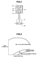
- the intake and exhaust valves 5 and 6 are actuated by electromagnetic actuators, such as one as shown in Fig. 2.
- the electromagnetic actuator comprises an armature plate 22 which is secured to a stem 21 of a valve 20.
- the armature plate 22 is held in a neutral position by upper and lower springs 23 and 24.
- the valve closing coil 26 is deenergized and then the valve opening coil 25 is energized.
- the armature plate 22 is shifted downward together with the valve 20 thereby to induce an open condition of the valve 20.
- the valve opening coil 25 is deenergized and then the valve closing coil 26 is energized.
- the armature plate 22 is shifted upward together with the valve 20 thereby to induce a close condition of the valve 20.
- an electronically controlled throttle valve 9 in the intake passage 7 at position upstream of the intake manifold, there is arranged an electronically controlled throttle valve 9. If desired, at a position upstream of the throttle valve 9, there may be arranged a pressure-charging device, such as turbocharger, supercharger or the like. In each branch of the intake manifold, there is arranged an electromagnetic fuel injection valve 10.
- the open/close movements of the electromagnetically actuated intake and exhaust valves 5 and 6 are controlled.
- the close timing "IVC" of the intake valves 5 is variably controlled for controlling the intake air amount thereby to substantially carry out the non-throttle operation of the engine.
- the throttle valve 9 works to produce a negative pressure in the intake manifold, that is needed for canister purging, crankcase purging and the like.
- the fuel injection amount and fuel injection timing of each fuel injector 10 are controlled in accordance with operation condition of the engine 1. That is, basically, the fuel injection amount is so set as to provide a desired air/fuel ratio based on the intake air amount "Qa" detected by the air flow meter 14, and with the injection ending timing being fixed to a given point before the top dead center "TDC" of intake stroke, the fuel injection starting timing is controlled so as to obtain the set fuel injection amount.
- variable cycle operation will be described in detail with respect to a four cylinder engine 1.
- the engine 1 operates on the four stroke cycle, that is, (1) intake ⁇ (2) compression (ignition) ⁇ (3) explosion ⁇ (4) exhaust (during which, fuel injection takes place in the induction system). The expansion occurs at intervals of 180° in crank angle in case of the four cylinder engine 1.
- the cylinders are subjected to 4-cycle operation or 12-cycle operation respectively. That is, if the ignition order is #1 ⁇ #3 ⁇ #4 ⁇ #2, the cylinders #1 and #4 constitute a first group and the cylinders #2 and #3 constitute a second group, and the cylinders (for example, #1 and #4) of one of the groups are subjected to 4-cycle operation and the cylinders (for example, #2 and #3) of the other group are subjected to 12-cycle operation.
- step S1 the accelerator opening degree "APO” and the engine speed “Ne” are read, and at step S2, a target torque (viz., target intake air amount) "TQ" is looked up from a data map of Fig. 5 which shows the relation between "APO", “Ne” and "TQ".
- a target torque viz., target intake air amount
- the operation range of the engine 1 is judged with reference to a map of Fig. 3 which shows the relation between "Ne", "TQ" and the operation range. If the judgment shows the normal operation range "A”, the operation flow goes to step S4 to carry out 4-cycle operation. If the judgment shows the high-speed and low-load operation range "B”, the operation flow goes to step S5 to carry out 12-cycle operation. While, if the judgment shows the intermediate operation range "C" between the normal operation range "A” and the high-speed and low-load operation range "B”, the operation flow goes to step S6 to cause the cylinders to carry out 4-cycle and 12-cycle operations. That is, two cylinders are subjected to 4-cycle operation and the other two cylinders are subjected to 12-cycle operation.
- a data map for deriving the intake valve close timing "IVC” is selected. Then, at step S10, the intake valve close timing "IVC" for establishing the target torque (viz., target intake air amount) "TQ" is looked up from the selected data map which shows the relation between "Ne", "TQ" and "IVC".
- Fig. 6 shows a data map for looking up the "IVC" in 4-cycle operation.
- the engine 1 upon assuming the high-speed and low-load operation, the engine 1 is subjected to a cycle switching from 4-cycle operation to 12-cycle operation (viz., multi-cycle operation).
- the engine 1 sufficiently reduces its output torque, which brings about expansion of the torque-controllable non-throttle operation range of the engine 1.
- the intermediate operation range between 4-cycle operation range and the multi-cycle operation range a half (viz., two) of the cylinders are subjected to 4-cycle operation and the other half (viz., two) of the same are subjected to the multi-cycle operation (viz., 12-cycle operation), which brings about both control of the torque gap and further expansion of the torque-controllable non-throttle operation range of the engine 1.
- the multi-cycle operation viz., 12-cycle operation
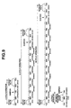
- each cylinder is subjected to the two stroke cycle, in which during downward movement of the piston (namely, in the middle of the explosion stroke after the piston has reached the top dead center "TDC"), the intake and exhaust valves are opened at generally same time to bring about the air intake and gas discharge simultaneously at the time near (namely, just before and after) the bottom dead center “BDC" of the piston, and during upward movement of the piston (namely, in the middle of the piston lifting stroke after the piston has reached the bottom dead center “BDC”), the intake and exhaust valves are closed at generally same time to bring about a so-called compression stroke, and when the piston comes to a position just before the top dead center "TDC", ignition takes place to bring about a subsequent explosion stroke.
- TDC top dead center
- the cylinders are subjected to 4-cycle operation or 2-cycle operation respectively. That is, if the ignition order is #1 ⁇ #3 ⁇ #4 ⁇ #2, the cylinders #1 and #4 constitute a first group and the cylinders #2 and #3 constitute a second group, and the cylinders (for example, #1 and #4) of one of the groups are subjected to 4-cycle operation and the cylinders (for example, #2 and #3) of the other group are subjected to 2-cycle operation.
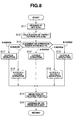
- step S11 the acceleration opening degree "APO” and the engine speed “Ne” are read and at step S12, a target torque (viz., target intake air amount) "TQ" is looked up from a data map which shows the relation between "APO", “Ne” and “TQ”.
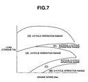
- step S13 the operation range of the engine 1 is judged with reference to the map of Fig. 7 which shows the relation between "Ne", "TQ” and the operation range. If the judgment shows the normal operation range "A”, the operation flow goes to step S14 to carry out 4-cycle operation. If the judgment shows the high-speed and low-load operation range "B”, the operation flow goes to step S15 to carry out 12-cycle operation.
- step S16 If the judgment shows the intermediate operation range "C" between the normal operation range “A” and the high-speed and low-load operation range “B”, the operation flow goes to step S16 to cause the cylinders to carry out 4-cycle and 12-cycle operations. That is, two cylinders are subjected to 4-cycle operation and the other two cylinders are subjected to 12-cycle operation. If the judgment shows the high-load range "D”, the operation flow goes to step S17 to carry out 2-cycle operation. While, if the judgment shows the intermediate operation range "E” of higher-speed side between the normal operation range "A” and the high-load operation range “D”, the operation flow goes to step S18 to cause the cylinders to carry out 4-cycle and 2-cycle operations. That is, two cylinders are subjected to 4-cycle operation and the other two cylinders are subjected to 2-cycle operation.
- step S19 based on the operation range "A", “B”, “C”, “D” or “E” thus judged, a data map for deriving the intake valve close timing "IVC” is selected. Then, at step S20, the intake valve close timing "IVC” for establishing the target torque (viz., target intake air amount) "TQ" is looked up from the selected data map which shows the relation between "Ne", "TQ" and "IVC".
- the present invention is also applicable to a six cylinder engine. In this case, in the high-speed and low-load operation range, it preferable to cause the engine to carry out 16-cycle operation.
Landscapes
- Engineering & Computer Science (AREA)
- Chemical & Material Sciences (AREA)
- Combustion & Propulsion (AREA)
- Mechanical Engineering (AREA)
- General Engineering & Computer Science (AREA)
- Output Control And Ontrol Of Special Type Engine (AREA)
- Valve-Gear Or Valve Arrangements (AREA)
- Valve Device For Special Equipments (AREA)
Applications Claiming Priority (2)
| Application Number | Priority Date | Filing Date | Title |
|---|---|---|---|
| JP2000081891A JP2001263110A (ja) | 2000-03-23 | 2000-03-23 | 可変動弁エンジンの制御装置 |
| JP2000081891 | 2000-03-23 |
Publications (2)
| Publication Number | Publication Date |
|---|---|
| EP1136678A2 true EP1136678A2 (fr) | 2001-09-26 |
| EP1136678A3 EP1136678A3 (fr) | 2002-08-28 |
Family
ID=18598761
Family Applications (1)
| Application Number | Title | Priority Date | Filing Date |
|---|---|---|---|
| EP01107185A Withdrawn EP1136678A3 (fr) | 2000-03-23 | 2001-03-22 | Système de réglage pour un moteur à combustion interne avec commande des soupapes variable |
Country Status (3)
| Country | Link |
|---|---|
| US (1) | US6523504B2 (fr) |
| EP (1) | EP1136678A3 (fr) |
| JP (1) | JP2001263110A (fr) |
Cited By (5)
| Publication number | Priority date | Publication date | Assignee | Title |
|---|---|---|---|---|
| EP1447548A1 (fr) * | 2003-02-17 | 2004-08-18 | Ford Global Technologies, Inc. | Procédé et système de commande de couple dans un véhicule |
| US6910449B2 (en) | 2002-12-30 | 2005-06-28 | Ford Global Technologies, Llc | Method for auto-ignition operation and computer readable storage device for use with an internal combustion engine |
| AT501183A1 (de) * | 2004-08-19 | 2006-07-15 | Avl List Gmbh | Verfahren zum betrieb einer brennkraftmaschine |
| WO2006017870A3 (fr) * | 2004-08-19 | 2008-11-27 | Avl List Gmbh | Procede pour faire fonctionner un moteur a combustion interne |
| FR3010452A1 (fr) * | 2013-09-10 | 2015-03-13 | Peugeot Citroen Automobiles Sa | Moteur a combustion de vehicule automobile a desactivation de cylindre amelioree |
Families Citing this family (38)
| Publication number | Priority date | Publication date | Assignee | Title |
|---|---|---|---|---|
| SE523773C2 (sv) * | 2001-09-07 | 2004-05-18 | Cargine Engineering Ab | Modulering av vridmoment i en förbränningsmotor |
| US7131933B2 (en) * | 2001-12-07 | 2006-11-07 | Toyota Jidosha Kabushiki Kaisha | Vehicle control apparatus having means for changing inertia torque of engine during shifting action or during switching of operating state of lock-up clutch |
| SE524802C2 (sv) * | 2002-11-04 | 2004-10-05 | Cargine Engineering Ab | Styrmetod för modulering av vridmoment i en kolvförbränningsmotor |
| DE10357986B4 (de) * | 2002-12-12 | 2016-09-01 | Denso Corporation | Variable Ventilsteuervorrichtung für einen Verbrennungsmotor |
| US7559309B2 (en) | 2004-03-19 | 2009-07-14 | Ford Global Technologies, Llc | Method to start electromechanical valves on an internal combustion engine |
| US7128687B2 (en) * | 2004-03-19 | 2006-10-31 | Ford Global Technologies, Llc | Electromechanically actuated valve control for an internal combustion engine |
| US7031821B2 (en) * | 2004-03-19 | 2006-04-18 | Ford Global Technologies, Llc | Electromagnetic valve control in an internal combustion engine with an asymmetric exhaust system design |
| US7079935B2 (en) * | 2004-03-19 | 2006-07-18 | Ford Global Technologies, Llc | Valve control for an engine with electromechanically actuated valves |
| US7555896B2 (en) | 2004-03-19 | 2009-07-07 | Ford Global Technologies, Llc | Cylinder deactivation for an internal combustion engine |
| US7107946B2 (en) * | 2004-03-19 | 2006-09-19 | Ford Global Technologies, Llc | Electromechanically actuated valve control for an internal combustion engine |
| US7194993B2 (en) * | 2004-03-19 | 2007-03-27 | Ford Global Technologies, Llc | Starting an engine with valves that may be deactivated |
| US7063062B2 (en) * | 2004-03-19 | 2006-06-20 | Ford Global Technologies, Llc | Valve selection for an engine operating in a multi-stroke cylinder mode |
| US7107947B2 (en) * | 2004-03-19 | 2006-09-19 | Ford Global Technologies, Llc | Multi-stroke cylinder operation in an internal combustion engine |
| US7165391B2 (en) | 2004-03-19 | 2007-01-23 | Ford Global Technologies, Llc | Method to reduce engine emissions for an engine capable of multi-stroke operation and having a catalyst |
| US7140355B2 (en) * | 2004-03-19 | 2006-11-28 | Ford Global Technologies, Llc | Valve control to reduce modal frequencies that may cause vibration |
| US7021289B2 (en) * | 2004-03-19 | 2006-04-04 | Ford Global Technology, Llc | Reducing engine emissions on an engine with electromechanical valves |
| US7072758B2 (en) * | 2004-03-19 | 2006-07-04 | Ford Global Technologies, Llc | Method of torque control for an engine with valves that may be deactivated |
| US7032581B2 (en) * | 2004-03-19 | 2006-04-25 | Ford Global Technologies, Llc | Engine air-fuel control for an engine with valves that may be deactivated |
| US7128043B2 (en) | 2004-03-19 | 2006-10-31 | Ford Global Technologies, Llc | Electromechanically actuated valve control based on a vehicle electrical system |
| US7240663B2 (en) * | 2004-03-19 | 2007-07-10 | Ford Global Technologies, Llc | Internal combustion engine shut-down for engine having adjustable valves |
| US7066121B2 (en) * | 2004-03-19 | 2006-06-27 | Ford Global Technologies, Llc | Cylinder and valve mode control for an engine with valves that may be deactivated |
| US7383820B2 (en) | 2004-03-19 | 2008-06-10 | Ford Global Technologies, Llc | Electromechanical valve timing during a start |
| GB2415744B (en) * | 2004-05-13 | 2008-10-29 | Anthony Edgar Blackburn | Engine cycles |
| US7080613B2 (en) * | 2004-07-12 | 2006-07-25 | General Motors Corporation | Method for auto-ignition combustion control |
| US20070068472A1 (en) * | 2005-03-31 | 2007-03-29 | Wilson Wayne M | Variable Valve Operating System for an Internal Combustion Engine |
| US8430067B2 (en) * | 2005-05-12 | 2013-04-30 | Ford Global Technologies, Llc | Engine starting for engine having adjustable valve operation |
| US7377236B2 (en) | 2005-09-09 | 2008-05-27 | Ford Global Technologies, Llc | System and method for exhaust heat generation using electrically actuated cylinder valves and variable stroke combustion cycles |
| US7337762B2 (en) * | 2005-10-06 | 2008-03-04 | Gm Global Technology Operations, Inc. | Fuel adaptation in a homogeneous charge compression ignition engine |
| JP4674180B2 (ja) * | 2006-03-31 | 2011-04-20 | 大阪瓦斯株式会社 | エンジン及びヒートポンプシステム |
| US7418928B2 (en) * | 2006-04-28 | 2008-09-02 | Caterpillar Inc. | Engine and method for operating an engine |
| JP2008019835A (ja) * | 2006-07-14 | 2008-01-31 | Mazda Motor Corp | 過給機付きエンジン |
| US20080022666A1 (en) * | 2006-07-31 | 2008-01-31 | Driscoll James J | Balanced partial two-stroke engine |
| JP2006348947A (ja) * | 2006-08-18 | 2006-12-28 | Kazuo Oyama | 排気圧回生機付内燃機関 |
| US7946259B2 (en) * | 2008-09-10 | 2011-05-24 | Ford Global Technologies, Llc | Multi-stroke internal combustion engine |
| US7997237B2 (en) | 2008-09-10 | 2011-08-16 | Ford Global Technologies, Llc | Multi-stroke internal combustion engine |
| CN102325976A (zh) | 2008-12-22 | 2012-01-18 | 卡特彼勒公司 | 执行稀燃6冲程循环的发动机控制系统 |
| JP6643930B2 (ja) * | 2015-03-31 | 2020-02-12 | 大阪瓦斯株式会社 | エンジンシステム |
| CN106930846B (zh) * | 2015-12-29 | 2021-03-19 | 长城汽车股份有限公司 | 多冲程循环发动机的控制方法、系统及车辆 |
Citations (2)
| Publication number | Priority date | Publication date | Assignee | Title |
|---|---|---|---|---|
| JPH08200025A (ja) | 1995-01-20 | 1996-08-06 | Toyota Motor Corp | 電磁駆動バルブ制御装置 |
| JP2000045804A (ja) | 1998-08-04 | 2000-02-15 | Nissan Motor Co Ltd | 内燃機関のトルク制御装置 |
Family Cites Families (14)
| Publication number | Priority date | Publication date | Assignee | Title |
|---|---|---|---|---|
| DE2703067A1 (de) | 1977-01-26 | 1978-07-27 | Peter R Dr Ing Kuhn | Mehrtakt-ottomotor |
| DE2740045A1 (de) * | 1977-09-06 | 1979-03-15 | Bayerische Motoren Werke Ag | Verfahren zur teillast-steuerung von brennkraftmaschinen |
| JPH01305129A (ja) * | 1988-06-02 | 1989-12-08 | Nissan Motor Co Ltd | 内燃機関 |
| US4945870A (en) * | 1988-07-29 | 1990-08-07 | Magnavox Government And Industrial Electronics Company | Vehicle management computer |
| EP0387372B1 (fr) | 1989-03-14 | 1994-05-25 | Vasant Mukund Joshi | Machine à combustion interne |
| US5022353A (en) * | 1989-04-26 | 1991-06-11 | Isuzu Ceramics Research Institute Co., Ltd. | Variable-cycle engine |
| DE69107021T2 (de) * | 1990-11-13 | 1995-05-18 | Isuzu Ceramics Research Institute Co. Ltd., Fujisawa, Kanagawa | Zwei oder Viertaktverbrennungskraftmaschine und sein Steuerungssystem. |
| US5117790A (en) * | 1991-02-19 | 1992-06-02 | Caterpillar Inc. | Engine operation using fully flexible valve and injection events |
| US5154141A (en) * | 1991-11-20 | 1992-10-13 | Mcwhorter Edward M | Dual cycle engine process |
| US5515818A (en) * | 1993-12-15 | 1996-05-14 | Machine Research Corporation Of Chicago | Electromechanical variable valve actuator |
| US5517951A (en) * | 1994-12-02 | 1996-05-21 | Paul; Marius A. | Two stroke/four stroke engine |
| US5699758A (en) * | 1996-02-15 | 1997-12-23 | Caterpillar Inc. | Method and apparatus for multiple cycle internal combustion engine operation |
| DE19810933C2 (de) * | 1998-03-13 | 2001-08-16 | Daimler Chrysler Ag | Verbrennungsmotor |
| SE521741C2 (sv) | 1999-06-24 | 2003-12-02 | Volvo Personvagnar Ab | Metod för att styra en flertaktsmotor |
-
2000
- 2000-03-23 JP JP2000081891A patent/JP2001263110A/ja active Pending
-
2001
- 2001-03-19 US US09/810,532 patent/US6523504B2/en not_active Expired - Fee Related
- 2001-03-22 EP EP01107185A patent/EP1136678A3/fr not_active Withdrawn
Patent Citations (2)
| Publication number | Priority date | Publication date | Assignee | Title |
|---|---|---|---|---|
| JPH08200025A (ja) | 1995-01-20 | 1996-08-06 | Toyota Motor Corp | 電磁駆動バルブ制御装置 |
| JP2000045804A (ja) | 1998-08-04 | 2000-02-15 | Nissan Motor Co Ltd | 内燃機関のトルク制御装置 |
Cited By (8)
| Publication number | Priority date | Publication date | Assignee | Title |
|---|---|---|---|---|
| US6910449B2 (en) | 2002-12-30 | 2005-06-28 | Ford Global Technologies, Llc | Method for auto-ignition operation and computer readable storage device for use with an internal combustion engine |
| US7400966B2 (en) | 2002-12-30 | 2008-07-15 | Ford Global Technologies, Llc | Method for auto-ignition operation and computer readable storage device for use with an internal combustion engine |
| US7441538B2 (en) | 2002-12-30 | 2008-10-28 | Ford Global Technologies, Llc | Method for auto-ignition operation and computer storage device for use with an internal combustion engine |
| US7793637B2 (en) | 2002-12-30 | 2010-09-14 | Ford Global Technologies, Llc | Method for auto-ignition operation and computer readable storage device for use with an internal combustion engine |
| EP1447548A1 (fr) * | 2003-02-17 | 2004-08-18 | Ford Global Technologies, Inc. | Procédé et système de commande de couple dans un véhicule |
| AT501183A1 (de) * | 2004-08-19 | 2006-07-15 | Avl List Gmbh | Verfahren zum betrieb einer brennkraftmaschine |
| WO2006017870A3 (fr) * | 2004-08-19 | 2008-11-27 | Avl List Gmbh | Procede pour faire fonctionner un moteur a combustion interne |
| FR3010452A1 (fr) * | 2013-09-10 | 2015-03-13 | Peugeot Citroen Automobiles Sa | Moteur a combustion de vehicule automobile a desactivation de cylindre amelioree |
Also Published As
| Publication number | Publication date |
|---|---|
| US20010023667A1 (en) | 2001-09-27 |
| US6523504B2 (en) | 2003-02-25 |
| JP2001263110A (ja) | 2001-09-26 |
| EP1136678A3 (fr) | 2002-08-28 |
Similar Documents
| Publication | Publication Date | Title |
|---|---|---|
| US6523504B2 (en) | Control system for controlling variable valve type internal combustion engine | |
| EP0659984B1 (fr) | Système de commande et procédé pour soupapes de moteur à combustion interne | |
| US5765528A (en) | Idle speed control system for automotive internal combustion engine | |
| US6161521A (en) | Internal combustion engine having deceleration fuel shut off and camshaft controlled charge trapping | |
| US7347170B2 (en) | Frequency modulated VCR-engine | |
| WO2007110774A2 (fr) | Système et procédé de détermination de demande d'accélération, et système et procédé de commande destinés à un moteur à combustion interne | |
| KR100815035B1 (ko) | 내연 기관의 밸브 작동 제어 장치 | |
| US7290524B2 (en) | Control apparatus and method for four-stroke premixed compression ignition internal combustion engine | |
| US6269793B1 (en) | Internal combustion engine having deceleration fuel shut off and camshaft controlled charge trapping | |
| US6688293B2 (en) | System and method for auto-ignition support | |
| EP1104842B1 (fr) | Dispositif de commande d'air d'admission d'un moteur à combustion interne | |
| JP5116465B2 (ja) | 内燃機関を運転する方法およびその方法を実施する内燃機関 | |
| US20010006058A1 (en) | System and method of controlling ignition timing in an engine with a variably operated intake valve | |
| JP2000087749A (ja) | 火花点火式内燃機関 | |
| US20200088115A1 (en) | Method for compensating a gas spring effect during cylinder shut-off with exhaust gas trapping | |
| JP2008303744A (ja) | 内燃機関の制御装置 | |
| JP3827861B2 (ja) | 休筒式エンジンの制御装置 | |
| JP4238629B2 (ja) | 内燃機関のアイドル振動低減装置 | |
| JP3620381B2 (ja) | 可変動弁エンジンの制御装置 | |
| US8151748B2 (en) | Internal combustion engine comprising a variable valve lift profile system and a method for controlling valve lift profile shifting | |
| JP2000045804A (ja) | 内燃機関のトルク制御装置 | |
| JP2009052505A (ja) | 内燃機関 | |
| Asmus | Effects of valve events on engine operation | |
| JPH10103092A (ja) | 電磁式吸・排気弁を有するエンジン制御装置 | |
| US10550771B2 (en) | Control device of internal-combustion engine |
Legal Events
| Date | Code | Title | Description |
|---|---|---|---|
| PUAI | Public reference made under article 153(3) epc to a published international application that has entered the european phase |
Free format text: ORIGINAL CODE: 0009012 |
|
| 17P | Request for examination filed |
Effective date: 20010322 |
|
| AK | Designated contracting states |
Kind code of ref document: A2 Designated state(s): AT BE CH CY DE DK ES FI FR GB GR IE IT LI LU MC NL PT SE TR |
|
| AX | Request for extension of the european patent |
Free format text: AL;LT;LV;MK;RO;SI |
|
| PUAL | Search report despatched |
Free format text: ORIGINAL CODE: 0009013 |
|
| AK | Designated contracting states |
Kind code of ref document: A3 Designated state(s): AT BE CH CY DE DK ES FI FR GB GR IE IT LI LU MC NL PT SE TR |
|
| AX | Request for extension of the european patent |
Free format text: AL;LT;LV;MK;RO;SI |
|
| AKX | Designation fees paid |
Designated state(s): DE FR GB |
|
| STAA | Information on the status of an ep patent application or granted ep patent |
Free format text: STATUS: THE APPLICATION HAS BEEN WITHDRAWN |
|
| 18W | Application withdrawn |
Effective date: 20041018 |