EP1136770A2 - Bouilleur pour système d'absorption à diffusion - Google Patents
Bouilleur pour système d'absorption à diffusion Download PDFInfo
- Publication number
- EP1136770A2 EP1136770A2 EP01100949A EP01100949A EP1136770A2 EP 1136770 A2 EP1136770 A2 EP 1136770A2 EP 01100949 A EP01100949 A EP 01100949A EP 01100949 A EP01100949 A EP 01100949A EP 1136770 A2 EP1136770 A2 EP 1136770A2
- Authority
- EP
- European Patent Office
- Prior art keywords
- cooker
- tubes
- wall
- space
- reservoir
- Prior art date
- Legal status (The legal status is an assumption and is not a legal conclusion. Google has not performed a legal analysis and makes no representation as to the accuracy of the status listed.)
- Granted
Links
- 238000010521 absorption reaction Methods 0.000 title claims description 10
- VHUUQVKOLVNVRT-UHFFFAOYSA-N Ammonium hydroxide Chemical compound [NH4+].[OH-] VHUUQVKOLVNVRT-UHFFFAOYSA-N 0.000 claims abstract description 13
- 235000011114 ammonium hydroxide Nutrition 0.000 claims abstract description 13
- 238000010438 heat treatment Methods 0.000 claims description 10
- 238000009792 diffusion process Methods 0.000 claims description 8
- 230000015572 biosynthetic process Effects 0.000 claims description 3
- 238000009413 insulation Methods 0.000 claims description 3
- 239000007788 liquid Substances 0.000 claims description 3
- 230000000149 penetrating effect Effects 0.000 claims 1
- QGZKDVFQNNGYKY-UHFFFAOYSA-N Ammonia Chemical compound N QGZKDVFQNNGYKY-UHFFFAOYSA-N 0.000 description 11
- 239000007789 gas Substances 0.000 description 10
- 229910021529 ammonia Inorganic materials 0.000 description 5
- 238000004519 manufacturing process Methods 0.000 description 5
- 238000010276 construction Methods 0.000 description 4
- 239000003507 refrigerant Substances 0.000 description 3
- 230000000694 effects Effects 0.000 description 2
- 239000008236 heating water Substances 0.000 description 2
- 239000000463 material Substances 0.000 description 2
- 238000000034 method Methods 0.000 description 2
- 239000000203 mixture Substances 0.000 description 2
- 238000005057 refrigeration Methods 0.000 description 2
- 239000002904 solvent Substances 0.000 description 2
- XLYOFNOQVPJJNP-UHFFFAOYSA-N water Substances O XLYOFNOQVPJJNP-UHFFFAOYSA-N 0.000 description 2
- UGFAIRIUMAVXCW-UHFFFAOYSA-N Carbon monoxide Chemical compound [O+]#[C-] UGFAIRIUMAVXCW-UHFFFAOYSA-N 0.000 description 1
- UFHFLCQGNIYNRP-UHFFFAOYSA-N Hydrogen Chemical compound [H][H] UFHFLCQGNIYNRP-UHFFFAOYSA-N 0.000 description 1
- 230000002745 absorbent Effects 0.000 description 1
- 239000002250 absorbent Substances 0.000 description 1
- 239000006096 absorbing agent Substances 0.000 description 1
- 239000012223 aqueous fraction Substances 0.000 description 1
- IHTRHZMXELXCEJ-UHFFFAOYSA-N azane;helium Chemical compound [He].N IHTRHZMXELXCEJ-UHFFFAOYSA-N 0.000 description 1
- 238000009835 boiling Methods 0.000 description 1
- 239000012159 carrier gas Substances 0.000 description 1
- 230000005494 condensation Effects 0.000 description 1
- 238000009833 condensation Methods 0.000 description 1
- 238000001816 cooling Methods 0.000 description 1
- 125000004122 cyclic group Chemical group 0.000 description 1
- 230000007423 decrease Effects 0.000 description 1
- 238000011161 development Methods 0.000 description 1
- 230000018109 developmental process Effects 0.000 description 1
- 239000003546 flue gas Substances 0.000 description 1
- 239000001307 helium Substances 0.000 description 1
- 229910052734 helium Inorganic materials 0.000 description 1
- SWQJXJOGLNCZEY-UHFFFAOYSA-N helium atom Chemical compound [He] SWQJXJOGLNCZEY-UHFFFAOYSA-N 0.000 description 1
- 239000001257 hydrogen Substances 0.000 description 1
- 229910052739 hydrogen Inorganic materials 0.000 description 1
- 239000000126 substance Substances 0.000 description 1
Images
Classifications
-
- F—MECHANICAL ENGINEERING; LIGHTING; HEATING; WEAPONS; BLASTING
- F25—REFRIGERATION OR COOLING; COMBINED HEATING AND REFRIGERATION SYSTEMS; HEAT PUMP SYSTEMS; MANUFACTURE OR STORAGE OF ICE; LIQUEFACTION SOLIDIFICATION OF GASES
- F25B—REFRIGERATION MACHINES, PLANTS OR SYSTEMS; COMBINED HEATING AND REFRIGERATION SYSTEMS; HEAT PUMP SYSTEMS
- F25B15/00—Sorption machines, plants or systems, operating continuously, e.g. absorption type
- F25B15/10—Sorption machines, plants or systems, operating continuously, e.g. absorption type with inert gas
-
- F—MECHANICAL ENGINEERING; LIGHTING; HEATING; WEAPONS; BLASTING
- F25—REFRIGERATION OR COOLING; COMBINED HEATING AND REFRIGERATION SYSTEMS; HEAT PUMP SYSTEMS; MANUFACTURE OR STORAGE OF ICE; LIQUEFACTION SOLIDIFICATION OF GASES
- F25B—REFRIGERATION MACHINES, PLANTS OR SYSTEMS; COMBINED HEATING AND REFRIGERATION SYSTEMS; HEAT PUMP SYSTEMS
- F25B33/00—Boilers; Analysers; Rectifiers
-
- F—MECHANICAL ENGINEERING; LIGHTING; HEATING; WEAPONS; BLASTING
- F25—REFRIGERATION OR COOLING; COMBINED HEATING AND REFRIGERATION SYSTEMS; HEAT PUMP SYSTEMS; MANUFACTURE OR STORAGE OF ICE; LIQUEFACTION SOLIDIFICATION OF GASES
- F25B—REFRIGERATION MACHINES, PLANTS OR SYSTEMS; COMBINED HEATING AND REFRIGERATION SYSTEMS; HEAT PUMP SYSTEMS
- F25B2333/00—Details of boilers; Analysers; Rectifiers
- F25B2333/004—Details of boilers; Analysers; Rectifiers the generator or boiler uses an inert gas as pressure equalizing medium
-
- F—MECHANICAL ENGINEERING; LIGHTING; HEATING; WEAPONS; BLASTING
- F25—REFRIGERATION OR COOLING; COMBINED HEATING AND REFRIGERATION SYSTEMS; HEAT PUMP SYSTEMS; MANUFACTURE OR STORAGE OF ICE; LIQUEFACTION SOLIDIFICATION OF GASES
- F25B—REFRIGERATION MACHINES, PLANTS OR SYSTEMS; COMBINED HEATING AND REFRIGERATION SYSTEMS; HEAT PUMP SYSTEMS
- F25B2500/00—Problems to be solved
- F25B2500/05—Cost reduction
-
- F—MECHANICAL ENGINEERING; LIGHTING; HEATING; WEAPONS; BLASTING
- F25—REFRIGERATION OR COOLING; COMBINED HEATING AND REFRIGERATION SYSTEMS; HEAT PUMP SYSTEMS; MANUFACTURE OR STORAGE OF ICE; LIQUEFACTION SOLIDIFICATION OF GASES
- F25B—REFRIGERATION MACHINES, PLANTS OR SYSTEMS; COMBINED HEATING AND REFRIGERATION SYSTEMS; HEAT PUMP SYSTEMS
- F25B2500/00—Problems to be solved
- F25B2500/21—Reduction of parts
-
- Y—GENERAL TAGGING OF NEW TECHNOLOGICAL DEVELOPMENTS; GENERAL TAGGING OF CROSS-SECTIONAL TECHNOLOGIES SPANNING OVER SEVERAL SECTIONS OF THE IPC; TECHNICAL SUBJECTS COVERED BY FORMER USPC CROSS-REFERENCE ART COLLECTIONS [XRACs] AND DIGESTS
- Y02—TECHNOLOGIES OR APPLICATIONS FOR MITIGATION OR ADAPTATION AGAINST CLIMATE CHANGE
- Y02A—TECHNOLOGIES FOR ADAPTATION TO CLIMATE CHANGE
- Y02A30/00—Adapting or protecting infrastructure or their operation
- Y02A30/27—Relating to heating, ventilation or air conditioning [HVAC] technologies
-
- Y—GENERAL TAGGING OF NEW TECHNOLOGICAL DEVELOPMENTS; GENERAL TAGGING OF CROSS-SECTIONAL TECHNOLOGIES SPANNING OVER SEVERAL SECTIONS OF THE IPC; TECHNICAL SUBJECTS COVERED BY FORMER USPC CROSS-REFERENCE ART COLLECTIONS [XRACs] AND DIGESTS
- Y02—TECHNOLOGIES OR APPLICATIONS FOR MITIGATION OR ADAPTATION AGAINST CLIMATE CHANGE
- Y02B—CLIMATE CHANGE MITIGATION TECHNOLOGIES RELATED TO BUILDINGS, e.g. HOUSING, HOUSE APPLIANCES OR RELATED END-USER APPLICATIONS
- Y02B30/00—Energy efficient heating, ventilation or air conditioning [HVAC]
- Y02B30/62—Absorption based systems
Definitions
- the invention relates to a cooker for a diffusion absorption system according to the preamble of claim 1.
- Diffusion absorption systems have long been known as small refrigeration systems for use in household refrigerators. With a corresponding design, they can also be used as heat pumps for heating or cooling purposes.
- the refrigerant ammonia (NH 3 ) and water are used as a pair of substances in these systems.
- the water as the solvent is the absorbent material, with hydrogen or helium generally being used as the pressure-compensating carrier gas.
- the ammonia-water mixture sets in motion when heat is added due to temperature and concentration differences. The heat is supplied in a cooker. Boiling expels gas bubbles from the NH 3 -rich solution.
- the water fraction in this gas stream is separated or returned in the rectifier, so that almost only NH 3 vapor flows to the condenser.
- the gas bubble pump must be designed so that it pumps the liquid to a considerable height in order to generate the necessary driving force.
- the high-purity ammonia vapor condenses and releases the heat of condensation into the heating water.
- the liquid ammonia then flows down into the evaporator. In the helium-ammonia atmosphere, the ammonia evaporates while absorbing ambient energy.
- the gas mixture then passes through a gas-gas heat exchanger and flows to the absorber, where the gaseous ammonia is absorbed by the low-NH 3 ammonia-water solution and releases the heat of absorption to the heating water before the noise-free process starts again.
- each flame tube touches two pump tubes and is welded to them.
- the pump pipes run as separate individual components directly in the central flue gas chimney.
- the invention has for its object the construction of a stove for a diffusion absorption system to optimize and thereby reduce the manufacturing effort.
- the cooker for a diffusion absorption system is characterized in that several cooker tubes are arranged in a closed, pressure-resistant container in a circle around a central heating device with an exhaust gas chimney lying above it.
- An annular cylindrical space is created around the stove pipes, which is delimited in the lower area on the inside by a wall around the heating device or further above by the exhaust gas fireplace.
- Another wall forms the outer jacket around the stove pipes.
- the space between the inner and outer wall is filled in particular with poor ammonia-water solution.
- the cooker tubes are preferably straight and end with their end face on an annular flange plate in the lower suction space, are connected to it or fixed to it with a precise fit.
- the annulus is dimensioned such that the vapor formation inside penetrates from below rich ammonia-water solution by the transferred from the inside Heat is initially promoted. The insulation effect decreases with the formation of steam further to.
- the additional wall is either sealed with the stove pipes enclosing wall connected or fixed precisely to this. Mainly This prevents ammonia vapor from accumulating in the intake chamber or reservoir forms and rises.
- the annular flange plate can approximately on the Level of the upper area of the reservoir.
- the stove pipes are also fixed to it, but they protrude from the - just like the surrounding wall Flange plate made with a freely protruding end in the intake space.
- the lower stove pipe area completely surrounded by rich ammonia-water solution and the insulating effect between the space around the heated stove pipes and the outside The area of the surrounding suction space or reservoir is thus also given.
- the outer jacket around the stove pipes does not have to be pressure-resistant, but essentially just be a liquid-tight wall.
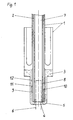
- the cooker with vertically aligned cooker tubes 2 and the reservoir 3 for the refrigerant or solvent are arranged in a common pressure-resistant container 1.
- the container 1 forms a suction space 5 for the rich ammonia-water solution. This is heated with a centrally arranged heating device 6 in the cooker.
- the exhaust gas chimney 7 extends in an extension of the heating device 6, ie within the circularly arranged cooker tubes 2. It is delimited by an inner wall 8. Together with another wall 9, which encloses the stove pipes 2 from the outside, an annular cylindrical space 10 is created.
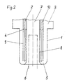
- annular space 11 open at the bottom with a wall 12 is located on the outside of the wall 9 and extends at least over the lower area with the heating device 6 or the area with the highest temperatures inside. It isolates the space 10 from the surrounding suction space 5 or the reservoir 3. According to FIG. 2, the annular flange plate 4 can also be attached approximately at the level of the upper region of the reservoir 3 for insulation purposes.
- the cooker tubes 2 and the surrounding wall 9 protrude from there with a freely projecting end into the lower region of the suction space 5.
Landscapes
- Engineering & Computer Science (AREA)
- Physics & Mathematics (AREA)
- Mechanical Engineering (AREA)
- Thermal Sciences (AREA)
- General Engineering & Computer Science (AREA)
- Power Engineering (AREA)
- Cookers (AREA)
- Sorption Type Refrigeration Machines (AREA)
- Gas Separation By Absorption (AREA)
- General Preparation And Processing Of Foods (AREA)
- Treating Waste Gases (AREA)
Applications Claiming Priority (2)
| Application Number | Priority Date | Filing Date | Title |
|---|---|---|---|
| DE10014128 | 2000-03-22 | ||
| DE10014128A DE10014128C1 (de) | 2000-03-22 | 2000-03-22 | Kocher für eine Diffusionsabsorptionsanlage |
Publications (3)
| Publication Number | Publication Date |
|---|---|
| EP1136770A2 true EP1136770A2 (fr) | 2001-09-26 |
| EP1136770A3 EP1136770A3 (fr) | 2002-07-17 |
| EP1136770B1 EP1136770B1 (fr) | 2005-11-23 |
Family
ID=7635848
Family Applications (1)
| Application Number | Title | Priority Date | Filing Date |
|---|---|---|---|
| EP01100949A Expired - Lifetime EP1136770B1 (fr) | 2000-03-22 | 2001-01-17 | Bouilleur pour système d'absorption à diffusion |
Country Status (3)
| Country | Link |
|---|---|
| EP (1) | EP1136770B1 (fr) |
| AT (1) | ATE310931T1 (fr) |
| DE (2) | DE10014128C1 (fr) |
Cited By (1)
| Publication number | Priority date | Publication date | Assignee | Title |
|---|---|---|---|---|
| CN103148640A (zh) * | 2013-03-20 | 2013-06-12 | 浙江腾云制冷科技有限公司 | 一种用于发生器的内管 |
Families Citing this family (2)
| Publication number | Priority date | Publication date | Assignee | Title |
|---|---|---|---|---|
| DE10219550B4 (de) * | 2002-04-25 | 2004-09-16 | Deutsches Zentrum für Luft- und Raumfahrt e.V. | Austreibervorrichtung |
| DE102009003912B4 (de) * | 2009-01-03 | 2011-11-03 | Robert Bosch Gmbh | Kocher für eine Diffusionsabsorptionsanlage |
Citations (2)
| Publication number | Priority date | Publication date | Assignee | Title |
|---|---|---|---|---|
| EP0413791B1 (fr) | 1989-03-14 | 1993-05-12 | STIERLIN, Hans | Absorbeur pour un systeme d'absorption diffusion |
| EP0419606B1 (fr) | 1989-03-14 | 1994-08-03 | STIERLIN, Hans | Purgeur avec pompe a bulles de gaz |
Family Cites Families (4)
| Publication number | Priority date | Publication date | Assignee | Title |
|---|---|---|---|---|
| DE478338C (de) * | 1929-06-22 | Sulzer Akt Ges Geb | Kocherabsorber fuer Absorptionskaeltemaschinen mit intermittierendem Betrieb | |
| US2030265A (en) * | 1931-06-12 | 1936-02-11 | Nygaard Johan Olsen | Water tube boiler |
| US4127993A (en) * | 1977-05-12 | 1978-12-05 | Allied Chemical Corporation | Method and generator unit of an absorption heat pump system for separating a rich liquor into a refrigerant and a solution low in refrigerant content |
| US5067330A (en) * | 1990-02-09 | 1991-11-26 | Columbia Gas System Service Corporation | Heat transfer apparatus for heat pumps |
-
2000
- 2000-03-22 DE DE10014128A patent/DE10014128C1/de not_active Expired - Fee Related
-
2001
- 2001-01-17 EP EP01100949A patent/EP1136770B1/fr not_active Expired - Lifetime
- 2001-01-17 DE DE50108123T patent/DE50108123D1/de not_active Expired - Lifetime
- 2001-01-17 AT AT01100949T patent/ATE310931T1/de active
Patent Citations (2)
| Publication number | Priority date | Publication date | Assignee | Title |
|---|---|---|---|---|
| EP0413791B1 (fr) | 1989-03-14 | 1993-05-12 | STIERLIN, Hans | Absorbeur pour un systeme d'absorption diffusion |
| EP0419606B1 (fr) | 1989-03-14 | 1994-08-03 | STIERLIN, Hans | Purgeur avec pompe a bulles de gaz |
Cited By (1)
| Publication number | Priority date | Publication date | Assignee | Title |
|---|---|---|---|---|
| CN103148640A (zh) * | 2013-03-20 | 2013-06-12 | 浙江腾云制冷科技有限公司 | 一种用于发生器的内管 |
Also Published As
| Publication number | Publication date |
|---|---|
| ATE310931T1 (de) | 2005-12-15 |
| EP1136770B1 (fr) | 2005-11-23 |
| EP1136770A3 (fr) | 2002-07-17 |
| DE50108123D1 (de) | 2005-12-29 |
| DE10014128C1 (de) | 2001-08-30 |
Similar Documents
| Publication | Publication Date | Title |
|---|---|---|
| DE602004001297T2 (de) | Absorptions-Klimaanlage | |
| DE10014128C1 (de) | Kocher für eine Diffusionsabsorptionsanlage | |
| EP0025986A1 (fr) | Procédé et dispositif pour l'utilisation de la chaleur recueillie à basse température | |
| EP2204627B1 (fr) | Réchaud pour une installation d'absorption par diffusion | |
| DE69511904T2 (de) | Heizungsanlage für ein gebäude mit wärmerohr | |
| DE10221188A1 (de) | Absorptions-Diffusions-Kühlstruktur | |
| EP1136771B1 (fr) | Rectificateur pour système d'absorption à diffusion | |
| DE10248557B4 (de) | Diffusionsabsorptionsanlage | |
| DE102011105742A1 (de) | Periodisch arbeitende Sorptionsvorrichtung | |
| DE10014124C1 (de) | Rektifikator für eine Diffusionsabsorptionsanlage | |
| CH265013A (de) | Kontinuierlich arbeitender Absorptionskälteapparat. | |
| DE4029995A1 (de) | Absorptionsmaschine | |
| DE497332C (de) | Absorptionsmaschine | |
| DE20005331U1 (de) | Diffusionsabsorptionsanlage | |
| DE202017007574U1 (de) | Verdampfervorrichtung | |
| DE10014122C5 (de) | Diffusionsabsorptionsanlage | |
| EP1278027B1 (fr) | Installation d'absorption à diffusion | |
| DE102005030793A1 (de) | Diffusionsabsorptionsanlage | |
| AT89464B (de) | Dampfwarmwasser-Heizkörper. | |
| DE1501009C (de) | Absorptionskälteanlage | |
| CH357419A (de) | Kocheraggregat an einer mit druckausgleichendem Hilfsgas arbeitenden Absorptionskältemaschine | |
| EP1136768A2 (fr) | Système d'absorption à diffusion | |
| DE29924391U1 (de) | Absorptionskühlanordnung | |
| DE20023150U1 (de) | Diffusionsabsorptionsanlage | |
| CH247836A (de) | Verdampfer mit senkrecht stehenden Heizrohren. |
Legal Events
| Date | Code | Title | Description |
|---|---|---|---|
| PUAI | Public reference made under article 153(3) epc to a published international application that has entered the european phase |
Free format text: ORIGINAL CODE: 0009012 |
|
| AK | Designated contracting states |
Kind code of ref document: A2 Designated state(s): AT BE CH CY DE DK ES FI FR GB GR IE IT LI LU MC NL PT SE TR |
|
| AX | Request for extension of the european patent |
Free format text: AL;LT;LV;MK;RO;SI |
|
| 17P | Request for examination filed |
Effective date: 20020306 |
|
| PUAL | Search report despatched |
Free format text: ORIGINAL CODE: 0009013 |
|
| AK | Designated contracting states |
Kind code of ref document: A3 Designated state(s): AT BE CH CY DE DK ES FI FR GB GR IE IT LI LU MC NL PT SE TR |
|
| AX | Request for extension of the european patent |
Free format text: AL;LT;LV;MK;RO;SI |
|
| AKX | Designation fees paid |
Designated state(s): AT CH DE LI NL |
|
| RAP1 | Party data changed (applicant data changed or rights of an application transferred) |
Owner name: BBT THERMOTECHNIK GMBH |
|
| RAP1 | Party data changed (applicant data changed or rights of an application transferred) |
Owner name: BBT THERMOTECHNIK GMBH |
|
| GRAP | Despatch of communication of intention to grant a patent |
Free format text: ORIGINAL CODE: EPIDOSNIGR1 |
|
| GRAS | Grant fee paid |
Free format text: ORIGINAL CODE: EPIDOSNIGR3 |
|
| GRAA | (expected) grant |
Free format text: ORIGINAL CODE: 0009210 |
|
| AK | Designated contracting states |
Kind code of ref document: B1 Designated state(s): AT CH DE LI NL |
|
| REG | Reference to a national code |
Ref country code: CH Ref legal event code: EP |
|
| REF | Corresponds to: |
Ref document number: 50108123 Country of ref document: DE Date of ref document: 20051229 Kind code of ref document: P |
|
| REG | Reference to a national code |
Ref country code: CH Ref legal event code: NV Representative=s name: ISLER & PEDRAZZINI AG |
|
| RAP2 | Party data changed (patent owner data changed or rights of a patent transferred) |
Owner name: ROBERT BOSCH GMBH |
|
| NLT2 | Nl: modifications (of names), taken from the european patent patent bulletin |
Owner name: ROBERT BOSCH GMBH Effective date: 20060329 |
|
| PLBE | No opposition filed within time limit |
Free format text: ORIGINAL CODE: 0009261 |
|
| STAA | Information on the status of an ep patent application or granted ep patent |
Free format text: STATUS: NO OPPOSITION FILED WITHIN TIME LIMIT |
|
| 26N | No opposition filed |
Effective date: 20060824 |
|
| REG | Reference to a national code |
Ref country code: CH Ref legal event code: PCAR Free format text: ISLER & PEDRAZZINI AG;POSTFACH 1772;8027 ZUERICH (CH) |
|
| REG | Reference to a national code |
Ref country code: DE Ref legal event code: R084 Ref document number: 50108123 Country of ref document: DE Effective date: 20120919 |
|
| PGFP | Annual fee paid to national office [announced via postgrant information from national office to epo] |
Ref country code: DE Payment date: 20140325 Year of fee payment: 14 Ref country code: NL Payment date: 20140122 Year of fee payment: 14 Ref country code: CH Payment date: 20140124 Year of fee payment: 14 |
|
| PGFP | Annual fee paid to national office [announced via postgrant information from national office to epo] |
Ref country code: AT Payment date: 20140122 Year of fee payment: 14 |
|
| REG | Reference to a national code |
Ref country code: DE Ref legal event code: R119 Ref document number: 50108123 Country of ref document: DE |
|
| REG | Reference to a national code |
Ref country code: NL Ref legal event code: V1 Effective date: 20150801 |
|
| REG | Reference to a national code |
Ref country code: CH Ref legal event code: PL |
|
| REG | Reference to a national code |
Ref country code: AT Ref legal event code: MM01 Ref document number: 310931 Country of ref document: AT Kind code of ref document: T Effective date: 20150117 |
|
| PG25 | Lapsed in a contracting state [announced via postgrant information from national office to epo] |
Ref country code: NL Free format text: LAPSE BECAUSE OF NON-PAYMENT OF DUE FEES Effective date: 20150801 |
|
| PG25 | Lapsed in a contracting state [announced via postgrant information from national office to epo] |
Ref country code: DE Free format text: LAPSE BECAUSE OF NON-PAYMENT OF DUE FEES Effective date: 20150801 Ref country code: CH Free format text: LAPSE BECAUSE OF NON-PAYMENT OF DUE FEES Effective date: 20150131 Ref country code: LI Free format text: LAPSE BECAUSE OF NON-PAYMENT OF DUE FEES Effective date: 20150131 |
|
| PG25 | Lapsed in a contracting state [announced via postgrant information from national office to epo] |
Ref country code: AT Free format text: LAPSE BECAUSE OF NON-PAYMENT OF DUE FEES Effective date: 20150117 |