EP1136995B1 - Dispositif de lecture de code à barres et procédé pour son usage dans un changeur automatique de supports de données - Google Patents
Dispositif de lecture de code à barres et procédé pour son usage dans un changeur automatique de supports de données Download PDFInfo
- Publication number
- EP1136995B1 EP1136995B1 EP01302133A EP01302133A EP1136995B1 EP 1136995 B1 EP1136995 B1 EP 1136995B1 EP 01302133 A EP01302133 A EP 01302133A EP 01302133 A EP01302133 A EP 01302133A EP 1136995 B1 EP1136995 B1 EP 1136995B1
- Authority
- EP
- European Patent Office
- Prior art keywords
- support mechanism
- picker
- autochanger
- media
- imaging device
- Prior art date
- Legal status (The legal status is an assumption and is not a legal conclusion. Google has not performed a legal analysis and makes no representation as to the accuracy of the status listed.)
- Expired - Lifetime
Links
- 238000000034 method Methods 0.000 title claims description 20
- 238000003384 imaging method Methods 0.000 claims description 75
- 230000007246 mechanism Effects 0.000 claims description 75
- 230000003287 optical effect Effects 0.000 claims description 41
- 230000032258 transport Effects 0.000 description 4
- 238000012544 monitoring process Methods 0.000 description 2
- 230000001133 acceleration Effects 0.000 description 1
- 230000000737 periodic effect Effects 0.000 description 1
Images




Classifications
-
- G—PHYSICS
- G11—INFORMATION STORAGE
- G11B—INFORMATION STORAGE BASED ON RELATIVE MOVEMENT BETWEEN RECORD CARRIER AND TRANSDUCER
- G11B15/00—Driving, starting or stopping record carriers of filamentary or web form; Driving both such record carriers and heads; Guiding such record carriers or containers therefor; Control thereof; Control of operating function
- G11B15/675—Guiding containers, e.g. loading, ejecting cassettes
- G11B15/68—Automatic cassette changing arrangements; automatic tape changing arrangements
- G11B15/682—Automatic cassette changing arrangements; automatic tape changing arrangements with fixed magazines having fixed cassette storage cells, e.g. in racks
- G11B15/6835—Automatic cassette changing arrangements; automatic tape changing arrangements with fixed magazines having fixed cassette storage cells, e.g. in racks the cassettes being transferred to a fixed recorder or player using a moving carriage
-
- G—PHYSICS
- G11—INFORMATION STORAGE
- G11B—INFORMATION STORAGE BASED ON RELATIVE MOVEMENT BETWEEN RECORD CARRIER AND TRANSDUCER
- G11B17/00—Guiding record carriers not specifically of filamentary or web form, or of supports therefor
- G11B17/22—Guiding record carriers not specifically of filamentary or web form, or of supports therefor from random access magazine of disc records
- G11B17/225—Guiding record carriers not specifically of filamentary or web form, or of supports therefor from random access magazine of disc records wherein the disks are transferred from a fixed magazine to a fixed playing unit using a moving carriage
Definitions
- the following invention generally relates to an imaging device used in an autochanger and, more particularly, to a bar code reader movably attached to a media handling device used in an autochanger.
- An autochanger is a device that is used for storing large amounts of data on a plurality of media pieces, such as magnetic or optical media.
- An autochanger typically comprises a media library, a media handler, a media player, and a processor.
- the media library typically has a plurality of bays that store individual media pieces.
- the media player translates the data stored on the media pieces to a usable format, e.g., a binary format.
- the media player also writes data onto the media pieces.
- the media handler which may also be referred to herein as a "picker," transports the media pieces between the bays in the media library and the media player.
- the processor controls the movement of the media handler and indexes the locations of the media pieces within the autochanger.
- One of the uses of the autochanger is for backing up large amounts of data.
- a bank or other industry may have account information and the like stored as data in a storage system.
- the storage system provides for quick access to the account information during business hours.
- the bank or other industry may back up the data on a periodic basis, e.g., nightly, in case the data stored in the storage system becomes corrupt.
- the data stored in the storage system becomes corrupt, it can readily be replaced by transferring data from the media pieces stored in the autochanger to the storage system.
- that portion may be replaced by its copy stored in the autochanger.
- the autochanger may index portions of data to the locations on particular media pieces where the data is located.
- Some autochangers use media pieces that have optical indicia located thereon that serve to identify the individual media pieces.
- the optical indicia may, as an example, be conventional bar codes that correspond to alphanumeric characters, which identify each individual media piece.
- An optical reader may be attached to the media handling device and may serve to read the optical indicum.
- the optical reader may be a bar code reader.
- the autochanger uses the optical reader to "read" the optical indicia and, thus, to identify the individual media pieces located within the autochanger.
- Some autochangers have a scanning beam bar code reader attached to the media handler, which allows the autochanger to read the bar codes attached to the media pieces.
- Scanning beam bar code readers are typically expensive and comprise several moving parts, which makes them susceptible to failure.
- the increased susceptibility to failure is due to the scanning bar code readers being attached to the media handler, which moves throughout the autochanger. This movement typically causes relatively harsh acceleration forces to be applied to the bar code readers.
- the addition of scanning bar code readers to the autochanger increases the cost of the autochanger and reduces its reliability.
- the media library typically comprises several adjacent columns of media pieces.
- the media handler moves in a vertical direction to access media pieces stored in a particular column.
- the media handler also moves in a horizontal direction to access media pieces stored in different columns.
- An objective in the design of autochangers is to limit the size of the autochangers, thus, the media pieces in the library are typically compacted within a small space.
- the movement of the media handler should be limited so as not to require additional space in the autochanger for movement.
- Japanese Patent Application JP 05144156 discloses an automatic optical disk changer having an optical disk housing rack for holding optical disk containers. Each disk container has an identification mark on the outside, and the containers are arranged so that the identification marks are displayed in a row in the housing rack.
- the disk changer also includes an optical reader for detecting the identification marks, and a device for rotating the reader with respect to the changer.
- the reader is fitted on a supporting base and a laser beam is emitted from a head of the reader onto the identification mark to be read.
- the optical reader is operated by a robot system, and can be slid down a vertical supporting pillar to align the reader with the rack and read the identification marks on each of the containers.
- the present invention provides an autochanger and a method for reading optical indicia attached to media pieces, as recited in the appended claims.
- the autochanger may comprise a library and the media handling device that is movable relative to the library.
- the library may be adapted to hold a plurality of media pieces having optical indicia affixed thereto.
- the autochanger may move the media handling device to positions where the imaging device may read the optical indicia.
- the imaging device may move between the first operative position and the second operative position to read selected indicia. This movement allows the media handling device to move the imaging device to positions where it is able to read the indicia without the need to move beyond the confines of the autochanger.
- the attachment of the imaging device to the media handling device allows for relative movement between the imaging device and the media pieces.
- This relative movement may be used by the imaging device to read the indicia affixed to the media pieces by causing the imaging device to "scan" the indicia.
- the relative movement may be used by the imaging device to scan the bar codes.
- the imaging device may be a fixed beam bar code reader rather than a scanning beam bar code reader, which reduces the cost and improves the reliability of the autochanger.
- Figs. 1 through 10 in general, illustrate a media handling device 100 comprising a support mechanism 260 having a first portion 262 and a second portion 264.
- the first portion 262 is attached to the media handling device 162 and wherein the second portion 264 is movably associated with the first portion 262.
- An imaging device 250 is attached to the support mechanism second portion 264.
- the support mechanism second portion 264 has a first operative position and a second operative position relative to the support mechanism first portion 262.
- Figs. 1 through 10 also, in general, illustrate an autochanger 100.
- the autochanger 100 comprises a media library 160 having a plurality of media holding bays and a media handling device 162 movably associated with the media holding bays.
- the media handling device 162 comprises a support mechanism 260 having a first portion 262 and a second portion 264 wherein the first portion 262 is attached to the media handling device 162 and wherein the second portion 264 is movably associated with the first portion 262.
- the support mechanism second portion 264 has a first operative position and a second operative position relative to the support mechanism first portion 262.
- An imaging device 250 is attached to the support mechanism second portion 264.
- Figs. 1 through 10 also, in general, illustrate a method for reading optical indicia 196 attached to media pieces 170.
- the method comprises: providing a first media piece 180 located at a first position, the first media piece 180 having a first optical indicum 196 attached thereto; providing a second media piece 200 located at a second position, the second media piece 200 having a second optical indicum 196 attached thereto; providing a media handling device 162.
- the media handling device 162 comprising a support mechanism 260 having a first portion 262 and a second portion 264.
- the first portion 262 is attached to the media handling device 162 and the second portion 264 is movably associated with the first portion 262.
- the support mechanism second portion 264 has a first operative position and a second operative position relative to the support mechanism first portion 262.
- the method for reading optical indicia 196 further comprises: providing an imaging device 250 attached to the support mechanism second portion 264; moving the support mechanism second portion 264 to the first operative position; reading the first optical indicum 196 using the imaging device 250; moving the support mechanism second portion 264 to the second operative position; and reading the second optical indicum 196 using the imaging device 250.
- Figs. 1 through 10 also, in general, illustrate a method for reading an optical indicum 196 attached to a media piece 180.
- the method comprises: providing a media handling device 162, the media handling device 162 being movable relative to the optical indicum 162; providing a fixed beam imaging device 250 attached to the media handling device 162; causing relative movement between the imaging device 162 and the optical indicum 196; generating image data representative of the optical indicum 196 while the imaging device 162 is moved relative to the optical indicum 196.
- autochanger 100 may, for example, be of the type commercially available from the Hewlett-Packard Company and sold as Model Number HP 4228w or of the type described in the following United States Patents: 5,644,559 of Christie, et al., for FLIP LATCH ASSEMBLY FOR MEDIA AUTOCHANGER; and 5,682,096 of Christie, et al., for METHOD AND APPARATUS FOR MONITORING OPERATING POSITIONS OF A MEDIA AUTOCHANGER.
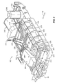
- FIG. 1 A cut away top perspective view of the autochanger 100 is illustrated in Fig. 1. It should be noted that for illustration purposes, the view of Fig. 1 is a rear view of the autochanger 100.
- the autochanger 100 and its components are described herein with reference to a horizontal direction 110 and a vertical direction 116.
- the horizontal direction 110 is sometimes referred to as a translational direction.
- the horizontal direction 110 may be described in greater detail with reference to a positive horizontal direction 112 and a negative horizontal direction 114.
- the vertical direction 116 may be described in greater detail with reference to a positive vertical direction 118 and a negative vertical direction 120.
- the components comprising the autochanger 100 may be located in a chassis 130. It should be noted that, for illustration purposes, not all the components comprising the autochanger 100 are illustrated as being located in the chassis 130 of Fig. 1.
- the chassis 130 may contain a library 160, a picker 162, an engagement member 164, and a media player 166. Servos and other drive mechanisms that move the picker 162 within the chassis 130 are not illustrated in Fig. 1.
- the chassis 130 may be a parallel-piped structure having a right portion 132, a left portion 134, top portion 136, a bottom portion 138, a rear portion 140, and a front portion 142.
- the right portion 132 and the left portion 134 may be separated by a width W1.
- One of the objectives in the design of the autochanger 100 is to minimize the size of the chassis 130, which is achieved, in part, by minimizing the width W1.
- the library 160 may contain a plurality of media pieces 170, wherein each media piece 170 is stored in an individual bay.
- the library 160 may have the media pieces 170 arranged in columns.
- the autochanger 100 illustrated in Fig. 1 has three columns in the library 160, a first column 174, a second column 176, and a third column 178, that extend in the vertical direction 116. It is to be understood that the use of three vertically extending columns of media pieces 170 is for illustration purposes only and that the autochanger 100 may have more or fewer columns and that the columns may extend in other directions.
- the media player 166 may be located in the proximity of the library 160 and may serve to read data from and write data to the media pieces 170 in a conventional manner. It should be noted that only one media player 166 is illustrated as being located in the chassis 130, however, it is to be understood that several media players 166 may be located in the chassis 130.
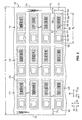
- FIG. 2 A partial front view of the library 160 with media pieces 170 located therein is illustrated in Fig. 2.
- the media pieces 170 are illustrated herein as being digital linear tape cartridges, however, it is to be understood that other forms of media may be used in place of the digital linear tape cartridges.
- Two media pieces, a first media piece 180 and a second media piece 200, will be used as references to describe all the media pieces 170 and the relations of the media pieces 170 to the chassis 130.
- the first media piece 180 may have a left side 182, a right side 184, a top side 186, a bottom side 188, and a front side 190.
- the left side 182 may be separated from the right side 184 by a width W2 and the top side 186 may be separated from the bottom side 188 by a height H1.
- the front side 190 may have a read/write portion 198 with a read/write switch 192 located therein.
- the read/write switch 192 may serve to prevent data from being erased from the media piece in a conventional manner.
- the front side 190 may also have an indicum portion 194 with an indicum 196 located therein.
- the indicum 196 may have a left portion 197 and a right portion 199.
- the indicum 196 may, as an example, be a conventional bar code that contains information, which identifies the first media piece 180. As illustrated in Fig. 2, the indicum portion 194 is located in the proximity of the right side 184 of the first media piece 180.
- the indicum 196 may, as an example, be a conventional bar code.
- the bar code may have a series of bars and spaces that extend in the vertical direction 116.
- the indicum 196 may represent an identification, such as an alphanumeric sequence, that distinguishes the individual media pieces from each other.
- the indicum 196 may be "read" from the left portion 197 to the right portion 199 by a conventional bar code reader in a conventional manner.
- the right side 184 of the first media piece 180 may be separated from the left portion 134 of the chassis 130 by a distance D1.
- the left side 182 of the second media piece 200 may be separated from the right portion 132 of the chassis 130 by a distance D2. Accordingly, the width W1 of the chassis 130 is dependant on the distance D1 and the distance D2.
- One method of meeting the design objective of having a small chassis 130 is by minimizing the distance D1 and the distance D2.
- the picker 162 may be located adjacent the library 160 and may move throughout the chassis 130 in the horizontal direction 110 and the vertical direction 116. As will be described in greater detail below, the picker 162 may serve to transport the media pieces 170 between the media player 166 and the library 160.
- the autochanger 100 may have servos and orientation systems that move the picker 162 within the autochanger 100 and determine the position of the picker 162 within the autochanger 100. Examples of servo and orientation systems used in an autochanger are described in United States patent number, 5,544,146 for CARTRIDGE HANDLING SYSTEM of Luffel et al..
- the chassis 130 may have a plurality of hard stops, not shown, that limit the movement of the picker 162 within the chassis 130.
- the current supplied to the servos moving the picker 162 against the hard stop will increase.
- the autochanger 100 is able to determine if the picker 162 has encountered a hard stop or other encumbrance within the autochanger 100.
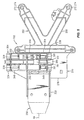
- Fig. 3 provides an enlarged view of the picker 162. It should be noted that the view of the picker 162 illustrated Fig. 3 is reversed from the view of the picker 162 illustrated in Fig. 1.
- the picker 162 may have a front portion 230, a rear portion 232, a left portion 234, a right portion 236, a top portion 238, and a bottom portion 240.
- the front portion 230 may have an opening 244 formed therein.
- the opening 244 may have a height H2 and a width W3, which may be appropriately sized to allow a media piece 170, Fig. 2, to pass into the picker 162.
- the top portion 238 of the picker 162 may have a first servo 246 and a second servo 248 attached thereto.
- the first servo 246 may serve to transport digital linear tapes through the opening 244, Fig. 3, in a conventional manner.
- the first servo 246 may serve to extract media pieces 170, Fig. 2, from and insert media pieces 170, Fig. 2, into the library 160.
- the second servo 248 may serve to move the picker 162 in the horizontal direction 110 in a conventional manner.
- a current monitor not shown, may be associated with the second servo 248 and may serve to indicate when the picker 162 encounters a hard stop or other encumbrance within the autochanger 100, Fig. 1.
- the top portion 238 of the picker 162 may have a support mechanism 260 attached thereto.
- Fig. 5 illustrates an enlarged view of the support mechanism 260.
- the support mechanism 260 may serve to slidably attach an imaging device 250 to the picker 162.
- the support mechanism 260 may have a first portion 262 slidably associated with a second portion 264.
- the first portion 262 may have a bracket 268 with a platform 270 attached thereto.
- the bracket 268 may have a plurality of holes 272 with screws 274 passing therethrough. The holes 272 in conjunction with the screws 274 serve to secure the support mechanism 260 to the picker 162.
- the platform 270 may have an upper side 276 and a lower side 278.
- a first retainer 280 and a second retainer 281 may be attached to or integrally formed with the upper side 276.
- the first retainer 280 and the second retainer 281 may be substantially similar to each other.
- the first retainer 280 may be a T-shaped device having a stem 282 attached to a cross member 284.
- the cross member 284 may have a first guide portion 286 and a second guide portion 288 facing the platform 270.
- the first guide portion 286 and the second guide portion 288 may be located a distance D3 from the upper side 276 of the platform 270. Referring again to Figs.
- first retainer 280 and the second retainer 281 may serve to guide the second portion 264 in the horizontal direction 110 relative to the first portion 262.
- the first retainer 280 and the second retainer 281 may also serve to retain the second portion 264 in close proximity to the first portion 262.
- the platform 270 may have a lock mechanism 290 associated therewith.
- the lock mechanism 290 may pass through the platform 270.
- the lock mechanism 290 may serve to lock the second portion 264 of the support mechanism 260 relative to the platform 270.
- the lock mechanism 290 may have a first lock 292 and a second lock 293, Fig. 5, located in a housing 294. Only the first lock 292 is illustrated in the side view of Fig. 7, however, both locks 292, 293, Fig. 5, are described with reference to the first lock 292 illustrated in Fig. 7.
- the first lock 292 may have a top portion 298, a bottom portion 300, a first slope 302, a second slope 304, a first extension 306, a second extension 308, a first contact surface 310, and a second contact surface 312.
- the first slope 302 and the second slope 304 may be substantially planar surfaces that are formed at an angle relative to the top portion 298.
- the first contact surface 310 and the second contact surface 312 may be portions of the first extension 306 and the second extension 308 that are adapted to contact the lower side 278 of the platform 270.
- the housing 294 may serve to contain the first lock 292 in the proximity of the platform 270.
- a spring 296 or other detent mechanism may be connected between the first lock 292 and the housing 294.
- the spring 296 may serve to bias the first lock 292 in the positive vertical direction 118.
- Moving the first lock 292 in the negative vertical direction 120 may be accomplished by applying a force in negative vertical direction 120 to the top portion 298 of the first lock 292.
- Moving the first lock 292 in the negative vertical direction 120 may also be accomplished by applying a force in the positive horizontal direction 112 to the second slope 304 or applying a force the negative horizontal direction 114 to the first slope 302.
- the first lock 292 and the second lock 293, Fig. 5 both may be located in the same housing 294 and connected to the same spring 296. Referring again to Figs. 4 and 5, the first lock 292 and the second lock 293 may extend through the platform 270 to engage the second portion 264 of the support mechanism 260.
- the second portion 264 of the support mechanism 260 may be operatively or slidably associated with the platform 270 and, thus, the first portion 262.
- the second portion 264 may have a slide 330 with a bracket 332 attached thereto.
- the bracket 332 may serve to support the imaging device 250.
- the slide 330 may have a first end portion 334 and a second end portion 336 with a first mid portion 338 and a second mid portion 339 located therebetween. Referring again to Fig. 7, which illustrates a side cut away view of the slide 330, including the first mid portion 338, the slide 330 may have a first stop 340 associated with the first end portion 334 and a second stop 342 associated with the second end portion 336.
- the first mid portion 338 may have a first open portion 346, a second open portion 348, and a closed portion 350.
- the first open portion 346 and the second open portion 348 may be appropriately sized so that the first lock 292 may pass through them.
- a first channel 344 may extend between the first stop 340 and the second stop 342 and may extend below the closed portion 350.
- the first channel 344 may be appropriately sized so as to accommodate the first lock 292, which allows the slide 330 to move in the horizontal direction 110 as is described in greater detail below.
- the second mid portion 339 may be substantially similar to the first mid portion 338.
- the second mid portion 339 may have a first open portion 352, a second open portion 354, and a closed portion 356 that are substantially similar to their corresponding parts of the first mid portion 338.
- a second channel, not shown, that is substantially similar to the first channel 344, Fig. 7, may extend between the first stop 340 and the second stop 342 and under the closed portion 356.
- the second channel may be appropriately sized to accommodate the second lock 293 as the second portion 264 moves relative to the first portion 262.
- the closed portions 350, 354 may serve to cover the first channel 344 and the second channel so as to recess the locks 292, 293 into the housing 294 as the slide 330 moves in the horizontal direction 110.
- the use of two mid portions 338, 339 in conjunction with the first and second retainers 280, 281 provides for a substantially linear movement of the second portion 264 relative to the first portion 262 in the horizontal direction 110.
- the first guide portion 286 and the second guide portion 288 may contact the first mid portion 338 and the second mid portion 339 respectively. This contact retains the slide 330 in close proximity to the upper side 276 of the platform 270. In addition, this contact provides for a linear movement of the slide 330 relative to the platform 270 in the horizontal direction 110.
- the second mid portion 339 may have a cable clasp 328 attached thereto.
- the cable clasp 328 may serve to secure a data and/or power cable, not shown, associated with the imaging device 250.
- the cable clasp 328 prevents the data and/or power cable from binding on components located within the autochanger 100, Fig. 1, as the second portion 264 and the picker 162 move relative to each other and throughout the autochanger 100, Fig. 1.
- the engagement member 164 may extend from the top portion 136 of the chassis 130.
- An enlarged side view of the engagement member 164 is illustrated in Fig. 8.
- the engagement member 164 may be a rigid member having an upper side 360 and a lower side 362.
- a first prong 364 and a second prong 366 may extend from the lower side 362.
- the mid section of the first prong 364 may be located a D4 from the top portion 136 of the chassis 130.
- a first hole 368 and a second hole 370 may extend through the engagement member 164 and the top portion 136 of the chassis 130.
- a first fastener 372 and a second fastener 374 may extend through the first hole 368 and the second hole 370 respectively. The first fastener 372 and the second fastener 374 may serve to attach the engagement member 164 to the top portion 136 of the chassis 130.
- the first prong 364 and the second prong 366 may be adapted to contact the first mid portion 338 and the second mid portion 339 of the slide 330. More specifically, they may serve to press the first lock 292 and the second lock 293 while pushing against either the first stop 340 or the second stop 342. This may be achieved by having the distance D4 appropriately sized so that the first prong 364 and the second prong 366 are able to contact the first mid portion 338 and the second mid portion 339. Accordingly, the first prong 364 may serve to release the locks 292, 293 in the support mechanism 260 and to move the second portion 264 relative to the first portion 262.
- the first prong 364 and the second prong 366 may also serve to press against the first stop 340 and the second stop 342 of the slide 330.
- the engagement member 164 may ultimately serve to move the imaging device 250 relative to the picker 162 as is described in greater detail below.
- the imaging device 250 may be secured to the bracket 332 of the second portion 264 in a conventional manner.
- the imaging device 250 may, as an example, be a conventional, stationary beam, bar code reader.
- the imaging device 250 may, as an example, be of the type commercially available from the Welch Allyn Company of Skaneateles Falls, New York and sold under the tradename SCANTEAM® 6500.
- the imaging device 250 may receive a pencil beam of light, which is illustrated as extending along an axis AA.
- the imaging device 250 may "read" an indicum 196, Fig. 2, by scanning the axis AA across an indicum 196, which causes the imaging device 250 to generate an image of the indicum 196.
- the imaging device 250 may output digital data that is representative of the image of the indicum 196, which may be processed by a processor, not shown.
- the autochanger 100 may have position sensors, not shown, that determine the position of the picker 162 within the autochanger 100.
- the autochanger 100 may also have sensors that determine if the picker 162 has encountered an obstacle or a hard stop.
- current sensors may monitor the current supplied to the second servo 248 and other servos, not shown, that move the picker 162 within the autochanger 100. If a servo attempts to move the picker 162 against an obstacle, the current drawn by the servo will increase. By monitoring the current, the autochanger 100 is able to determine if the picker 162 has encountered an obstacle or a hard stop. This technique may be used by the autochanger 100 to determine if the picker 162 has properly engaged the engagement member 164 as will be described in greater detail below.
- the autochanger 100 serves to store large quantities of data on the media pieces 170. This storage ability is accomplished by reading data from and writing data to the media pieces 170, which is performed by the media player 166.
- the picker 162 serves to transport the media pieces 170 between the library 160 and the media player 166.
- the autochanger 100 uses the imaging device 250 to read the indicia 196 attached to the media pieces 170. More specifically, the picker 162 moves the imaging device 250 in the horizontal direction 110 in order to provide relative movement between the imaging device 250 and an indicium 196. This movement causes the axis AA, Fig. 3, to scan the indicium 196. Accordingly, an image of the indicum 196 is received by the imaging device 250, which generates an image of the indicium 196. Generating an image of an indicum 196 is sometimes referred to as "reading" the indicum 196. Conventional processing is used to decode the indicium 196 and, thus, identify the media piece 170 to which the indicum 196 is attached.
- the picker 162 would have to move in the horizontal direction 110 beyond the columns of media pieces 170 in order for the imaging device 250 to scan the indicum 196. This extended movement would cause the distance D1 and/or the distance D2 to be increased, which would increase the width W1 of the autochanger 100.
- one of the design objectives of the autochanger 100 is to reduce the size and, thus, the width W1 of the autochanger 100.
- the autochanger 100 described above has minimal distances D1 and D2.
- the minimal distances D1 and D2 are achieved by moving the imaging device 250 to an optimal position when it reads the indicum 196. More specifically, the imaging device 250 is in a first position as illustrated in Figs. 1 and 4 when it reads the indicia 196 attached to the media pieces 170 located in the second column 176 and the third column 178. In order to read the indicia 196 attached to the media pieces 170 located in the first column 174, the imaging device 250 moves to a second position, which is illustrated in Fig. 9. Moving the imaging device 250 from the first position to the second position is performed by the autochanger 100 moving the picker 162 to a position where it engages the engagement member 164. Once engaged, the picker 162 moves in the horizontal direction 110, which causes the second portion 264 of the support mechanism 260 to move relative to the picker 162. Accordingly, the imaging device 250 moves between the first position and the second position relative to the picker 162.
- the autochanger 100 upon powering up the autochanger 100, the autochanger 100 does not know where the picker 162 is located within the autochanger 100, nor does the autochanger 100 know which position the imaging device 250 is in.
- the autochanger 100 inventory process commences with autochanger 100 determining the position of the picker 162 within the autochanger 100.
- the autochanger 100 moves the picker 162 in the negative vertical direction 120 until it can no longer move, meaning that the picker 162 has encountered a hard stop.
- This position is known as the negative vertical hard stop and may be sensed by a rise in the current being supplied to the servos, which is indicative of the picker 162 encountering a hard stop.
- the location of the negative vertical hard stop may be stored by the autochanger 100 for future processing.
- the autochanger 100 may then move the picker 162 in the positive horizontal direction 112 until the picker 162 encounters a hard stop.
- This location is referred to as the positive horizontal hard stop and may be stored by the autochanger 100 for future reference.
- the autochanger 100 has information stored therein pertaining to the distance from the positive horizontal hard stop to a point in the horizontal direction 110 where the second portion 264 of the support mechanism 260 aligns with the engagement member 164. Accordingly, the autochanger 100 moves the picker 162 in the negative horizontal direction 114 to this point.
- the autochanger 100 has information stored therein pertaining to the distance from the negative vertical stop to the engagement member 164.
- the autochanger 100 uses this information to move the picker 162 in the positive horizontal direction 112 to a point where the engagement member 164 may engage the second portion 264 of the support mechanism 260.
- the autochanger 100 then moves the picker 162 in the negative horizontal direction 114, which causes the second portion 264 of the support mechanism 260 to moves to the first position. More specifically, referring to Figs. 1, 4 and 6, the first prong 364 of the engagement member 164 contacts the first lock 292 and the second prong 366 contacts the second lock 293.
- the engagement member 164 causes the first lock 292 and the second lock 293 to depress into the platform 270.
- the depression of the first lock 292 and the second lock 293 into the platform 270 allows for the second portion 264 of the support mechanism 260 to be readily moved relative to the first portion 262.
- the autochanger 100 instructs the picker 162 to move in the negative horizontal direction 114 a predetermined distance, which causes the imaging device 250 to move to the first position. It should be note that in the event the imaging device 250 is located in the first position prior to the above-described process, the imaging device 250 will remain in the first position during the process.
- the autochanger 100 then orients itself with reference to the media pieces 170. This orientation is performed by moving the picker 162 in the negative vertical direction 120 until it encounters the negative vertical hard stop. The picker 162 is then moved in the positive horizontal direction 112 until it encounters the positive horizontal hard stop. The picker 162 is now in a known position relative to the media pieces 170 located in the library 160.
- the autochanger 100 may commence inventorying the media pieces 170.
- the autochanger 100 moves the picker 162 predetermined distances to a position wherein the imaging device 250 is able to read the optical indicum 196 attached to the first media piece 180. More specifically, the autochanger 100 moves the picker 162 to a point where the axis AA intersects the left portion 197 of the indicum 196.
- the autochanger 100 then moves the picker 162 in the positive horizontal direction 112 so that the axis AA scans the indicum 196. This movement continues until the axis AA intersects the right portion 199 of the indicum 196.
- the imaging device 250 generates image data representative of the indicum 196 in a conventional manner. The image data may identify the first media piece 180. Accordingly, the autochanger 100 is able to catalog the identity and location of the first media piece 180.
- the autochanger 100 then moves the picker 162 in the negative horizontal direction 114 and the positive vertical direction 118 to a point where the axis AA intersects the left portion 197 of the indicum 196 affixed to the media piece 170 located above the first media piece 180.
- the indicum 196 is read and the identity and location of the media piece are cataloged as described above with reference to the first media piece 180. This process of reading indicia 196 is repeated for all the media pieces 170 located in the third column 178. It should be noted that the operation of the reading the indicum 196 may proceed in either the positive horizontal direction 112 or the negative horizontal direction 114.
- the autochanger 100 then moves the picker 162 so that the imaging device 250 may read the indicia 196 affixed to the media pieces 170 located in the second column 176. It should be noted that the imaging device 250 may be located in either the first position or the second position, Fig. 9, to read the indicia 196 affixed to the media pieces 170 located in the second column 176.
- the imaging device 250 In order for the imaging device 250 to read the indicia 196 affixed to the media pieces 170 located in the first column 174, the imaging device 250 has to move to the second position relative to the picker 162 as illustrated in Fig. 9. If the imaging device 250 did not move, the picker 162 would have to move in the horizontal direction 110 beyond the right portion 132 of the chassis 130. Thus, an autochanger 100 with a larger width W1 would be required. The autochanger 100 moves in the horizontal direction 110 and the vertical direction 116 to a point where the first prong 364, Fig. 8, and the second prong 366 of the engagement member 164 contact the second stop 342, Fig. 7, of the slide 330. The first prong 364, Fig.
- the second prong 366 may also serve to depress the first lock 292 and the second lock 293.
- the picker 162 then moves in the positive horizontal direction 112, which causes the second portion 264 to move relative to the support mechanism 260. This in turn causes the imaging device 250, Fig. 9, to move to the second position.
- the autochanger 100 then causes the picker 162 to move the imaging device 250 to positions where the imaging device 250 may read the indicia 196 affixed to the media pieces 170 located in the first column 174.
- the autochanger 100 may write data to and read data from the media pieces 170. Because the locations and identities of the media pieces 170 are known, the picker 162 may move selected media pieces 170 to the media player 166 where data may be read from and written to the media pieces 170.
- sensors may be used to determine the location of the imaging device 250 relative to the picker 162.
- a switch or the like may be operatively associated with the support mechanism 260. The switch may toggle to a first direction when the imaging device 250 is located in the first position and the switch may toggle to a second direction when the support mechanism 260 is located in the second position.
- an electromechanical device may be operative associated between the imaging device 250 and the picker 162.
- the electromechanical device may move the imaging device 250 between the first position and the second position in a conventional manner.
- the imaging device 250, Fig. 3 is maintained in a fixed position relative to the picker 162.
- a non-movable support mechanism 260 may secure the imaging device 250 to the picker 162.
- the indicia 196, Fig. 2 are read as described above by providing relative movement between the imaging device 250 and the indicia 196.
Landscapes
- Automatic Tape Cassette Changers (AREA)
Claims (10)
- Changeur automatique (100) comprenant :ladite deuxième partie de mécanisme de support (264) comprenant une première partie opérationnelle et une deuxième partie opérationnelle par rapport à ladite première partie de mécanisme de support (262),un dispositif de prise (162) comprenant un premier côté (238) et un deuxième côté (240) ;un mécanisme de support (280) comprenant une première partie (262) et une deuxième partie (264), dans lequel ladite première partie (262) est fixée au dit dispositif de prise (162) et dans lequel ladite deuxième partie (264) est associée par glissement avec ladite première partie (262) ; etun dispositif de formation d'image (250) fixé à ladite deuxième partie de mécanisme de support (264) et adapté pour lire des indices optiques (196) fixés à des pièces de support (170) reçues dans ledit changeur automatique (100) ;
dans lequel ladite première partie de mécanisme de support (262) est fixée à un quelconque du premier côté (238) et du deuxième côté (240) du dispositif de prise (162) et est pourvue d'un dispositif de retenue (280) destiné à guider la deuxième partie (264), et un élément de verrouillage (292, 293) adapté pour verrouiller la deuxième partie (264) dans une quelconque des première et deuxième positions opérationnelles, et
la deuxième partie de mécanisme de support (264) est pourvue d'un guide (338, 339) mis en prise par glissement avec ledit dispositif de retenue (280). - Changeur automatique (100) selon la revendication 1, dans lequel ledit élément de verrouillage fait partie d'un mécanisme de verrouillage (290), ledit mécanisme de verrouillage (290) comprenant :ledit élément de verrouillage (292) s'étendant à travers ladite première partie de mécanisme de support (262) et mettant en prise ladite deuxième partie de mécanisme de support (264), ledit élément de verrouillage (292) présentant une position verrouillée et une position non verrouillée ; etun mécanisme de détente (296) associé de manière opérationnelle entre ladite première partie de mécanisme de support (262) et ledit élément de verrouillage (292), ledit mécanisme de détente (296) adapté pour solliciter ledit élément de verrouillage (292) dans ladite position verrouillée.
- Changeur automatique (100) selon la revendication 1 dans lequel ledit dispositif de formation d'image (250) est un lecteur de code à barres à faisceau fixe.
- Changeur automatique (100) selon la revendication 1, dans lequel ladite première partie de mécanisme de support (262) comprend en outre :dans lequel ledit support (268) est fixé au dit dispositif de prise (162) ;un support (268) et un mécanisme de détente (296) ;
dans lequel ledit dispositif de retenue (280) est fixé au dit support (268) ;
dans lequel ledit élément de verrouillage (292, 293) est associé de manière mobile avec ledit support (268) le long d'un deuxième axe (116) et dans lequel ledit élément de verrouillage (292, 293) comprend un état verrouillé et un état non verrouillé ;
dans lequel ledit mécanisme de détente (296) est associé de manière opérationnelle entre ledit support (268) et ledit élément de verrouillage (292, 293) et est adapté pour solliciter ledit élément de verrouillage (292, 293) dans ledit état verrouillé ; et
dans lequel ladite deuxième partie de mécanisme de support (264) comprend en outre :un élément de support (332) et un canal (338, 339) ;dans lequel ledit dispositif de formation d'image (250) est fixé au dit élément de support (332) ; etdans lequel ledit canal (338, 339) comprend une partie ouverte (346, 348, 352, 354) et une partie fermée (350, 356), dans lequel ledit canal (338, 339) met en prise ledit élément de verrouillage (292, 293), dans lequel ledit élément de verrouillage (292, 293) est dans ledit état verrouillé lorsque l'élément de verrouillage (292, 293) met en prise ladite partie ouverte de canal (346, 348, 352, 354) et dans lequel ledit élément de verrouillage (292, 293) est dans ledit état non verrouillé lorsque ledit élément de verrouillage (292, 293) met en prise la partie fermée de canal (350, 356). - Changeur automatique selon la revendication 1, comprenant en outre :une bibliothèque multimédia (160) comprenant une pluralité de baies de retenue multimédia ; dans lequelle dispositif de prise (162) est associé de manière mobile avec lesdites baies de retenue multimédia.
- Procédé de lecture d'indices optiques (196) fixés à des pièces multimédia (170), ledit procédé comprenant les étapes consistant à :fournir une première pièce multimédia (180) placée au niveau d'une première position, ladite première pièce multimédia (180) comprenant un premier indice optique (196) fixé sur celle-ci ;fournir une deuxième pièce multimédia (200) placée au niveau d'une deuxième position, ladite deuxième pièce multimédia (200) comprenant un deuxième indice optique (196) fixé sur celle-ci ;fournir un dispositif de prise (162) comprenant un premier côté (238) et un deuxième côté (240), ledit dispositif de prise (162) comprenant :un mécanisme de support (260) comprenant une première partie (262) et une deuxième partie (264), dans lequel ladite première partie (262) est fixée au dit dispositif de prise (162) et dans lequel ladite deuxième partie (264) est associée par glissement avec ladite première partie (262) ;ladite deuxième partie de mécanisme de support (264) comprenant une première position opérationnelle et une deuxième position opérationnelle par rapport à ladite première partie de mécanisme de support (262) ;ladite première partie de mécanisme de support (262) étant fixée à un quelconque dudit premier côté (238) dudit deuxième côté (240) dudit dispositif de prise (162) et étant pourvue d'un dispositif de retenue (280) destiné à guider ladite deuxième partie (264), et un élément de verrouillage (292, 293) adapté pour verrouiller ladite deuxième partie (264) dans une quelconque desdites première et deuxième positions opérationnelles ;ladite deuxième partie de mécanisme de support (264) étant pourvue d'un guide (338, 339) mis en prise par glissement avec ledit dispositif de retenue (280) ;fournir un dispositif de formation d'image (250) fixé à ladite deuxième partie de mécanisme de support (264) ;glisser ladite deuxième partie de mécanisme de support (264) vers ladite première position opérationnelle ;lire ledit premier indice optique (196) à l'aide dudit dispositif de formation d'image (250) ;glisser ladite deuxième partie de mécanisme de support (264) vers ladite deuxième position opérationnelle ; etlire ledit deuxième indice optique (196) à l'aide dudit dispositif de formation d'image (250).
- Procédé selon la revendication 6, comprenant en outre l'étape consistant à fournir un élément de mise en prise (164), dans lequel ledit déplacement de ladite deuxième partie de mécanisme de support (264) vers ladite première position opérationnelle comprend les étapes consistant à :déplacer ledit dispositif de prise (162) vers une position dans laquelle ledit élément de mise en prise (164) entre en contact avec ladite deuxième partie de mécanisme de support (264) ; etdéplacer ledit dispositif de prise par rapport au dit élément de mise en prise (164) dans lequel ladite deuxième partie d'élément de support (264) reste dans une position fixe par rapport au dit élément de mise en prise (164) jusqu'à ce que ladite deuxième partie de mécanisme de support (264) soit dans ladite première position opérationnelle.
- Procédé selon la revendication 6, comprenant en outre l'étape consistant à fournir une trajectoire de lumière (AA) entre ledit premier indice optique (196) et ledit dispositif de formation d'image (250), dans lequel ledit premier indice optique (196) comprend une première extrémité (197) et une deuxième extrémité (199), et dans lequel ladite étape consistant à lire le premier indice optique (196) comprend les étapes consistant à :déplacer ledit dispositif de prise (162) vers une position dans laquelle ladite trajectoire de lumière (AA) coupe ladite première extrémité de premier indice optique (197) ;déplacer ledit dispositif de prise (162) vers une position dans laquelle ladite trajectoire de lumière (AA) coupe ladite deuxième extrémité de premier indice optique (199) alors que ladite trajectoire de lumière (AA) coupe de manière continue ledit premier indice optique (196) ; etgénérer des données d'image représentatives dudit premier indice optique (196) à l'aide dudit dispositif de formation d'image (250).
- Changeur automatique selon la revendication 5 et comprenant en outre un châssis (130), ledit châssis (130) comprenant un élément de mise en prise (164) s'étendant depuis celui-ci, ledit élément de mise en prise (164) étant positionné pour entrer en contact avec ladite deuxième partie de mécanisme de support (264), pour déplacer de manière relative ladite deuxième partie de mécanisme de support (264) par rapport à ladite première partie de mécanisme de support (262).
- Changeur automatique (100) selon la revendication 5, comprenant en outre une première pièce multimédia (180), une deuxième pièce multimédia (200) et une trajectoire de lumière (AA), dans lequel ladite trajectoire de lumière (AA) s'étend entre ladite première pièce multimédia (180) et ledit dispositif de formation d'image (250) lorsque ladite deuxième partie de mécanisme de support (264) se trouve dans ladite première partie opérationnelle, et dans lequel ladite trajectoire de lumière (AA) s'étend entre ladite deuxième pièce multimédia (200) et ledit dispositif de formation d'image (250) lorsque ladite deuxième partie de mécanisme de support (264) est dans ladite deuxième position opérationnelle.
Applications Claiming Priority (2)
| Application Number | Priority Date | Filing Date | Title |
|---|---|---|---|
| US09/532,930 US6631102B2 (en) | 2000-03-22 | 2000-03-22 | Imaging device and method for use in an autochanger |
| US532930 | 2000-03-22 |
Publications (2)
| Publication Number | Publication Date |
|---|---|
| EP1136995A1 EP1136995A1 (fr) | 2001-09-26 |
| EP1136995B1 true EP1136995B1 (fr) | 2005-10-12 |
Family
ID=24123787
Family Applications (1)
| Application Number | Title | Priority Date | Filing Date |
|---|---|---|---|
| EP01302133A Expired - Lifetime EP1136995B1 (fr) | 2000-03-22 | 2001-03-08 | Dispositif de lecture de code à barres et procédé pour son usage dans un changeur automatique de supports de données |
Country Status (4)
| Country | Link |
|---|---|
| US (2) | US6631102B2 (fr) |
| EP (1) | EP1136995B1 (fr) |
| JP (1) | JP2001331991A (fr) |
| DE (1) | DE60113905T2 (fr) |
Families Citing this family (6)
| Publication number | Priority date | Publication date | Assignee | Title |
|---|---|---|---|---|
| US6631102B2 (en) * | 2000-03-22 | 2003-10-07 | Hewlett-Packard Development Company, L.P. | Imaging device and method for use in an autochanger |
| US7028314B2 (en) * | 2003-03-24 | 2006-04-11 | Hewlett-Packard Development Company, L.P. | Media storage system and method for identifying a storage location therein |
| US7333293B2 (en) * | 2004-06-29 | 2008-02-19 | Hewlett-Packard Development Company, L.P. | Storage system having a reader with a light sensing portion inclined with respect to an axis of a label of a storage medium |
| JP4328332B2 (ja) * | 2006-02-24 | 2009-09-09 | 富士通株式会社 | バーコード読取り装置、バーコード読取り方法、バーコード読取りプログラム及びライブラリ装置 |
| US7855938B2 (en) * | 2007-09-21 | 2010-12-21 | Tandberg Data Asa | Expandable data storage system and method with cartridge pass-through between cartridge handling units |
| US8276168B2 (en) * | 2008-06-13 | 2012-09-25 | Quantum Corporation | Data storage media accessibility in a media library |
Family Cites Families (25)
| Publication number | Priority date | Publication date | Assignee | Title |
|---|---|---|---|---|
| GB2109598B (en) | 1981-11-04 | 1985-07-10 | Sony Corp | Controlling electronic devices |
| US5041789A (en) * | 1989-01-03 | 1991-08-20 | Bruker Analytische Messtechnik Gmbh | Magnetic-resonance instrument employing barcode experiment specification |
| US5237467A (en) * | 1991-02-14 | 1993-08-17 | Exabyte Corporation | Cartridge handling apparatus and method with motion-responsive ejection |
| JPH052815A (ja) * | 1991-06-26 | 1993-01-08 | Nec Eng Ltd | 外部記憶装置 |
| JPH05144156A (ja) | 1991-11-25 | 1993-06-11 | Toshiba Corp | 光デイスク自動交換器 |
| JP3211313B2 (ja) | 1991-11-25 | 2001-09-25 | ソニー株式会社 | カセット・オートチェンジャー |
| US5323327A (en) * | 1992-05-01 | 1994-06-21 | Storage Technology Corporation | On-the-fly cataloging of library cell contents in an automated robotic tape library |
| US5427489A (en) * | 1992-11-25 | 1995-06-27 | Gte Vantage Incorporated | Apparatus for controlling an automated cassette library |
| JP3412193B2 (ja) * | 1993-06-29 | 2003-06-03 | 株式会社ニコン | 露光装置 |
| JPH0798923A (ja) * | 1993-09-29 | 1995-04-11 | Pioneer Electron Corp | ディスクチェンジャー |
| JP2999351B2 (ja) | 1993-09-30 | 2000-01-17 | 富士通株式会社 | ライブラリ装置 |
| US5544146B1 (en) | 1994-08-24 | 1998-03-03 | Hewlett Packard Co | Cartridge handling system |
| US5742445A (en) * | 1994-12-22 | 1998-04-21 | Fujitsu Limited | Magnetic tape machine using friction data in controlling accessor speed |
| US5644559A (en) | 1995-01-04 | 1997-07-01 | Hewlett-Packard Company | Flip latch assembly for media autochanger |
| US5682096A (en) | 1995-01-05 | 1997-10-28 | Hewlett-Packard Company | Method and apparatus for monitoring operating positions of a media autochanger |
| US5761161A (en) * | 1995-06-07 | 1998-06-02 | International Business Machines Corporation | Automated library system with vertically translating input/output station |
| JPH1125552A (ja) * | 1997-07-07 | 1999-01-29 | Fujitsu Ltd | ライブラリ装置 |
| US6120230A (en) * | 1997-08-25 | 2000-09-19 | Advanced Digital Information Corporation | Roller-inserter for use with cartridge style information storage media |
| US5999356A (en) * | 1997-08-29 | 1999-12-07 | International Business Machines Corporation | Data cartridge library with rotating storage stacks |
| US6008964A (en) * | 1997-11-14 | 1999-12-28 | Exabyte Corporation | Cartridge library and method of operation thereof |
| US6205093B1 (en) * | 1998-07-24 | 2001-03-20 | International Business Machines Corporation | Read only input system providing control information encoded in a bar code label for automated data storage library |
| US6246642B1 (en) * | 1999-04-13 | 2001-06-12 | Hewlett-Packard Company | Automated optical detection system and method |
| US6153999A (en) * | 1999-04-16 | 2000-11-28 | Storage Technology Corporation | Robotic library dead reckon targeting |
| US6203262B1 (en) * | 1999-05-10 | 2001-03-20 | Mark R. Frich | Cart loading system and method for library-like materials |
| US6631102B2 (en) * | 2000-03-22 | 2003-10-07 | Hewlett-Packard Development Company, L.P. | Imaging device and method for use in an autochanger |
-
2000
- 2000-03-22 US US09/532,930 patent/US6631102B2/en not_active Expired - Fee Related
-
2001
- 2001-03-08 EP EP01302133A patent/EP1136995B1/fr not_active Expired - Lifetime
- 2001-03-08 DE DE60113905T patent/DE60113905T2/de not_active Expired - Lifetime
- 2001-03-22 JP JP2001083521A patent/JP2001331991A/ja active Pending
-
2003
- 2003-06-16 US US10/463,485 patent/US6820273B2/en not_active Expired - Lifetime
Also Published As
| Publication number | Publication date |
|---|---|
| JP2001331991A (ja) | 2001-11-30 |
| EP1136995A1 (fr) | 2001-09-26 |
| DE60113905T2 (de) | 2006-07-20 |
| DE60113905D1 (de) | 2006-02-23 |
| US6631102B2 (en) | 2003-10-07 |
| US20020145949A1 (en) | 2002-10-10 |
| US6820273B2 (en) | 2004-11-16 |
| US20030218943A1 (en) | 2003-11-27 |
Similar Documents
| Publication | Publication Date | Title |
|---|---|---|
| KR100237934B1 (ko) | 자동 라이브러리 시스템 | |
| JP2999787B2 (ja) | カートリッジ受動係合アセンブリを備えた光ディスクカートリッジ取扱い装置 | |
| US4853925A (en) | Information memory unit | |
| US5995477A (en) | Data cartridge caddy-to-storage rack referencing method and apparatus | |
| US6028733A (en) | Data cartridge caddy-to-storage rack interlock and release system | |
| EP0877363B1 (fr) | Système de verrouillage et de déverrouillage de cassettes de données | |
| EP1136995B1 (fr) | Dispositif de lecture de code à barres et procédé pour son usage dans un changeur automatique de supports de données | |
| US5993045A (en) | Data cartridge caddy presence sensing method and apparatus | |
| US6760914B2 (en) | Disk reproducing apparatus | |
| EP1207490B1 (fr) | Système de lecture de code à barres double pour un système de stockage de données | |
| US5999500A (en) | Data cartridge interlock release actuator system | |
| US6775093B1 (en) | Data cartridge-to-caddy referencing system for a data cartridge handling mechanism within an autochanger | |
| JP4564217B2 (ja) | データ記憶システムおよび情報検出方法 | |
| JP2007213811A (ja) | データカートリッジの種類を識別するための媒体検出システム及び方法 | |
| KR19990037517A (ko) | 기록 매체 카트리지 장착 장치 | |
| US7088644B2 (en) | Methods for regulating the position of a plunge mechanism of a cartridge engaging assembly | |
| US7477479B2 (en) | Tape drive bezel for use with multiple accessors | |
| US20050085942A1 (en) | Inventory control device | |
| EP0877361A2 (fr) | Réceptacle de manipulation et de stockage de cassettes de données |
Legal Events
| Date | Code | Title | Description |
|---|---|---|---|
| PUAI | Public reference made under article 153(3) epc to a published international application that has entered the european phase |
Free format text: ORIGINAL CODE: 0009012 |
|
| AK | Designated contracting states |
Kind code of ref document: A1 Designated state(s): AT BE CH CY DE DK ES FI FR GB GR IE IT LI LU MC NL PT SE TR Kind code of ref document: A1 Designated state(s): DE FR GB |
|
| AX | Request for extension of the european patent |
Free format text: AL;LT;LV;MK;RO;SI |
|
| 17P | Request for examination filed |
Effective date: 20011121 |
|
| AKX | Designation fees paid |
Free format text: DE FR GB |
|
| 17Q | First examination report despatched |
Effective date: 20020919 |
|
| GRAP | Despatch of communication of intention to grant a patent |
Free format text: ORIGINAL CODE: EPIDOSNIGR1 |
|
| GRAS | Grant fee paid |
Free format text: ORIGINAL CODE: EPIDOSNIGR3 |
|
| GRAA | (expected) grant |
Free format text: ORIGINAL CODE: 0009210 |
|
| AK | Designated contracting states |
Kind code of ref document: B1 Designated state(s): DE FR GB |
|
| REG | Reference to a national code |
Ref country code: GB Ref legal event code: FG4D |
|
| REF | Corresponds to: |
Ref document number: 60113905 Country of ref document: DE Date of ref document: 20060223 Kind code of ref document: P |
|
| ET | Fr: translation filed | ||
| PLBE | No opposition filed within time limit |
Free format text: ORIGINAL CODE: 0009261 |
|
| STAA | Information on the status of an ep patent application or granted ep patent |
Free format text: STATUS: NO OPPOSITION FILED WITHIN TIME LIMIT |
|
| 26N | No opposition filed |
Effective date: 20060713 |
|
| PGFP | Annual fee paid to national office [announced via postgrant information from national office to epo] |
Ref country code: FR Payment date: 20100406 Year of fee payment: 10 |
|
| PGFP | Annual fee paid to national office [announced via postgrant information from national office to epo] |
Ref country code: GB Payment date: 20100326 Year of fee payment: 10 |
|
| PGFP | Annual fee paid to national office [announced via postgrant information from national office to epo] |
Ref country code: DE Payment date: 20100329 Year of fee payment: 10 |
|
| GBPC | Gb: european patent ceased through non-payment of renewal fee |
Effective date: 20110308 |
|
| REG | Reference to a national code |
Ref country code: FR Ref legal event code: ST Effective date: 20111130 |
|
| PG25 | Lapsed in a contracting state [announced via postgrant information from national office to epo] |
Ref country code: DE Free format text: LAPSE BECAUSE OF NON-PAYMENT OF DUE FEES Effective date: 20111001 Ref country code: FR Free format text: LAPSE BECAUSE OF NON-PAYMENT OF DUE FEES Effective date: 20110331 |
|
| REG | Reference to a national code |
Ref country code: DE Ref legal event code: R119 Ref document number: 60113905 Country of ref document: DE Effective date: 20111001 |
|
| PG25 | Lapsed in a contracting state [announced via postgrant information from national office to epo] |
Ref country code: GB Free format text: LAPSE BECAUSE OF NON-PAYMENT OF DUE FEES Effective date: 20110308 |