EP1137032A2 - Interrupteur magnétique - Google Patents
Interrupteur magnétique Download PDFInfo
- Publication number
- EP1137032A2 EP1137032A2 EP01106190A EP01106190A EP1137032A2 EP 1137032 A2 EP1137032 A2 EP 1137032A2 EP 01106190 A EP01106190 A EP 01106190A EP 01106190 A EP01106190 A EP 01106190A EP 1137032 A2 EP1137032 A2 EP 1137032A2
- Authority
- EP
- European Patent Office
- Prior art keywords
- armature
- contact
- core
- switch according
- yoke
- Prior art date
- Legal status (The legal status is an assumption and is not a legal conclusion. Google has not performed a legal analysis and makes no representation as to the accuracy of the status listed.)
- Withdrawn
Links
- XEEYBQQBJWHFJM-UHFFFAOYSA-N Iron Chemical compound [Fe] XEEYBQQBJWHFJM-UHFFFAOYSA-N 0.000 claims description 14
- 239000000463 material Substances 0.000 claims description 11
- 229910052742 iron Inorganic materials 0.000 claims description 7
- AJCDFVKYMIUXCR-UHFFFAOYSA-N oxobarium;oxo(oxoferriooxy)iron Chemical compound [Ba]=O.O=[Fe]O[Fe]=O.O=[Fe]O[Fe]=O.O=[Fe]O[Fe]=O.O=[Fe]O[Fe]=O.O=[Fe]O[Fe]=O.O=[Fe]O[Fe]=O AJCDFVKYMIUXCR-UHFFFAOYSA-N 0.000 claims description 4
- 230000005284 excitation Effects 0.000 claims description 2
- 230000004907 flux Effects 0.000 abstract description 8
- BGPVFRJUHWVFKM-UHFFFAOYSA-N N1=C2C=CC=CC2=[N+]([O-])C1(CC1)CCC21N=C1C=CC=CC1=[N+]2[O-] Chemical compound N1=C2C=CC=CC2=[N+]([O-])C1(CC1)CCC21N=C1C=CC=CC1=[N+]2[O-] BGPVFRJUHWVFKM-UHFFFAOYSA-N 0.000 description 9
- PXHVJJICTQNCMI-UHFFFAOYSA-N Nickel Chemical compound [Ni] PXHVJJICTQNCMI-UHFFFAOYSA-N 0.000 description 6
- 230000008901 benefit Effects 0.000 description 6
- 230000008878 coupling Effects 0.000 description 6
- 238000010168 coupling process Methods 0.000 description 6
- 238000005859 coupling reaction Methods 0.000 description 6
- 238000010276 construction Methods 0.000 description 5
- RYGMFSIKBFXOCR-UHFFFAOYSA-N Copper Chemical compound [Cu] RYGMFSIKBFXOCR-UHFFFAOYSA-N 0.000 description 3
- 229910052802 copper Inorganic materials 0.000 description 3
- 239000010949 copper Substances 0.000 description 3
- 230000007423 decrease Effects 0.000 description 3
- 230000035945 sensitivity Effects 0.000 description 3
- 239000007779 soft material Substances 0.000 description 3
- 229910000679 solder Inorganic materials 0.000 description 3
- 229910000640 Fe alloy Inorganic materials 0.000 description 2
- 229910000990 Ni alloy Inorganic materials 0.000 description 2
- 229910000639 Spring steel Inorganic materials 0.000 description 2
- 238000000151 deposition Methods 0.000 description 2
- 230000008021 deposition Effects 0.000 description 2
- 238000005259 measurement Methods 0.000 description 2
- 238000000034 method Methods 0.000 description 2
- 239000011253 protective coating Substances 0.000 description 2
- 230000001133 acceleration Effects 0.000 description 1
- 230000009471 action Effects 0.000 description 1
- 239000004020 conductor Substances 0.000 description 1
- 238000006073 displacement reaction Methods 0.000 description 1
- 230000000694 effects Effects 0.000 description 1
- 230000003628 erosive effect Effects 0.000 description 1
- 238000002347 injection Methods 0.000 description 1
- 239000007924 injection Substances 0.000 description 1
- 238000001746 injection moulding Methods 0.000 description 1
- 239000000696 magnetic material Substances 0.000 description 1
- 238000004519 manufacturing process Methods 0.000 description 1
- 229910052759 nickel Inorganic materials 0.000 description 1
- 239000004033 plastic Substances 0.000 description 1
- 229920003023 plastic Polymers 0.000 description 1
- 230000008569 process Effects 0.000 description 1
- 230000035939 shock Effects 0.000 description 1
- 238000004544 sputter deposition Methods 0.000 description 1
- 230000003313 weakening effect Effects 0.000 description 1
Images


Classifications
-
- H—ELECTRICITY
- H01—ELECTRIC ELEMENTS
- H01H—ELECTRIC SWITCHES; RELAYS; SELECTORS; EMERGENCY PROTECTIVE DEVICES
- H01H51/00—Electromagnetic relays
- H01H51/22—Polarised relays
- H01H51/2209—Polarised relays with rectilinearly movable armature
-
- H—ELECTRICITY
- H01—ELECTRIC ELEMENTS
- H01H—ELECTRIC SWITCHES; RELAYS; SELECTORS; EMERGENCY PROTECTIVE DEVICES
- H01H50/00—Details of electromagnetic relays
- H01H50/16—Magnetic circuit arrangements
- H01H50/163—Details concerning air-gaps, e.g. anti-remanence, damping, anti-corrosion
-
- H—ELECTRICITY
- H01—ELECTRIC ELEMENTS
- H01H—ELECTRIC SWITCHES; RELAYS; SELECTORS; EMERGENCY PROTECTIVE DEVICES
- H01H50/00—Details of electromagnetic relays
- H01H50/16—Magnetic circuit arrangements
- H01H50/18—Movable parts of magnetic circuits, e.g. armature
- H01H50/32—Latching movable parts mechanically
- H01H50/326—Latching movable parts mechanically with manual intervention, e.g. for testing, resetting or mode selection
Definitions
- the invention relates to a magnetic switch having a cup-shaped yoke, a core, a coil, an armature and a fixed contact and a movable contact.
- Magnetic switches of this kind are known, for example, from EP 0 442 311 A2, which discloses a magnetic switch in which a non-magnetic armature is moved by a permanent magnet fixedly connected thereto. During this, in the direction of movement of the armature, only an operational air gap between the permanent magnet and the core brings about the effect. Furthermore, the known magnetic switch has a small coupling surface between the permanent magnet and the core, which extends only over the inner region of the cup-shaped yoke.
- the known magnetic switch has the disadvantage that the coupling surface between the permanent magnet and the core, and thus the holding force of the magnet system, is only very small relative to the structural volume of the magnetic switch.
- This means that the known magnetic switch is not suitable for use as a battery disconnecting switch in a motor vehicle, where on the one hand large currents of a few thousand amps have to be switched, and where on the other hand vibrations and jolts act on the magnetic switch.
- To achieve a greater holding force it would be possible for special magnetic materials which generate a very strong magnetic field to be used. These have the disadvantage that they are expensive to procure and complicated to process.
- the object of the present invention is therefore to provide a magnetic switch which presses the movable contact onto the fixed contact with a high holding force while having a small structural volume.
- the invention specifies a magnetic switch having a yoke that has the shape of a cup with an axis of symmetry.
- the cup has a base and a wall and is open to one side.
- a core which has a radial core flange at its end facing the base.
- This radial core flange forms with the wall of the cup a marginal air gap with a width of H R .
- This marginal air gap has a magnetic resistance of W R .
- the cup contains a plate-shaped permanent magnet which is magnetised parallel to the axis of symmetry of the cup. The permanent magnet is arranged between the core flange and the base and is magnetically coupled thereto.
- a coil whereof the coil axis is the axis of symmetry of the cup.
- the cup is covered by a plate-shaped armature which forms with the yoke a yoke air gap with a width of H J and forms with the core a core air gap with a width of H K .
- the yoke and core air gaps together form, connected serially one behind the other, the operational air gap, which has a magnetic resistance of W A .
- there is arranged on the magnetic switch a means for lifting the armature axially away from the cup. In the closed condition of the magnetic switch, the following applies: W A ⁇ W R .
- a magnetic switch is produced which is shielded from the outside extremely well and has only extremely low scattering losses for the magnetic fields. Because the armature forms an operational air gap with the core and the cup-shaped yoke, a coupling surface which is as large as possible is formed with a particular predetermined structural volume. The large coupling surface between the armature and the yoke and the core respectively results in a large holding force of the magnetic switch in the closed condition. Because the magnetic resistance of the operational air gap is smaller than the magnetic resistance of the marginal air gap, it is ensured that the majority of the magnetic flux of the permanent magnet is conducted through the armature in the closed condition.
- the system polarised by the permanent magnet moreover has the advantage that only a short switch pulse has to be sent through the coil in order to close the switch, and the coil current can be returned to zero in the closed condition. This means, in particular, that low-power operation of the magnetic switch is possible.
- the ratio W R /W A In order to achieve the maximum holding force of the armature, it would be desirable for the ratio W R /W A to be as large as possible. This would ensure that all of the magnetic flux of the permanent magnet is guided through the armature without losses being produced by way of the marginal air gap.
- a very large ratio W R /W A would, however, mean that a high counter-excitation of the coil would be required to open the switch, in order to displace the magnetic field of the permanent magnet out of the core and guide it through the marginal air gap and the wall of the cup, back onto the underside of the permanent magnet. Consequently, for the magnetic switch to have a high sensitivity to switching off, it would be desirable for the ratio W R /W A to be in the order of magnitude of one.
- a magnetic switch according to the invention may for example readily be produced with the following dimensions: for the cup, a radial extent of between 10 mm and 50 mm is chosen. With a size such as this, a compact construction is possible for the magnetic switch, as is specifically necessary for its use as a battery disconnecting switch in a motor vehicle.
- the width of the yoke and core air gaps purely for reasons of the superficial roughness of the underside of the armature or of the surfaces of the cup wall and the core, the following range can readily be set: 0.005 mm ⁇ H J ⁇ 0.05 mm and 0.005 mm ⁇ H K ⁇ 0.05 mm.
- a wall thickness of the cup of approximately 1 mm is chosen, moreover, then a surface for the yoke air gap with a size of approximately 100 mm 2 is obtained.
- the core air gap or the marginal air gap is constructed to have approximately the same order of magnitude as regards their surfaces, then to fulfil the relation mentioned above between the magnetic resistances of the operational and the marginal air gaps, the following apply: 1 mm > H R > 0.1 mm.
- the said dimensions of the core and yoke air gaps relate to the closed condition of the switch. With a magnetic switch constructed in accordance with these example dimensions, a holding force of approximately 30 N can be achieved. The axial extent of the switch corresponds approximately to the radial extent. A magnetic switch of this type can be switched at a switching capacity of approximately 0.7 W.
- a magnetic switch in which the yoke, permanent magnet, core, coil and armature are arranged rotationally symmetrically about the axis of symmetry.
- the permanent magnet is of a material containing barium ferrite.
- Barium ferrite is a readily available, inexpensive material for a permanent magnet, which greatly simplifies production of the magnetic switch. Because of the high holding force of the magnetic switch according to the invention, expensive highly magnetised special materials for the permanent magnet can be dispensed with.
- Magnetically soft iron can very readily be demagnetised, which simplifies the displacement of the flux of the permanent magnet out of the core when the magnetic switch is opened. Furthermore, magnetically soft iron has a low magnetic resistance, as a result of which it is ideal for conducting the flux of the permanent magnet to the armature.
- a high holding force of the magnetic switch may be achieved in particular in that the core and the yoke are dimensioned, at least in the region of the corresponding air gaps, in cross-section such that in the closed condition and in the absence of excitation, that is to say when the coil current is 0, there is almost magnetic saturation.
- the armature is particularly advantageous for the armature to be constructed in accordance with the invention with a radially varying plate thickness such that there is almost magnetic saturation in the entire armature in the closed condition of the magnetic switch.
- the armature thinner at the edge than in the centre, since the cross-sectional surface available for the magnetic flux increases with the distance from the axis of symmetry.
- the thickness of the armature can be lessened accordingly with increasing distance from the axis of symmetry. This makes it possible to reduce the mass of the armature to the absolutely minimum amount required.
- a minimised armature mass of this kind has the advantage that the magnetic switch is less sensitive to vibrations or shocks, since in this case it is primarily the inert mass of the armature which determines the extent to which the armature can respond to rapid accelerations.
- the magnetic switch may be constructed to be particularly compact if, according to the invention, a hole running along the axis of symmetry is provided in the yoke, the permanent magnet, the core and the armature, and through this hole runs a pin.
- This pin is secured to the armature at one end, and at the other end is coupled to a movable contact which makes contact with a first fixed contact in the closed condition of the magnetic switch. With the aid of the movable contact and the fixed contact, the circuit of a motor vehicle, for example, may be switched.
- the movable contact is a flange-shaped contact disc which is arranged symmetrically with respect to the axis of symmetry and has a central hole.
- the pin is secured in the hole in the armature by means of flange-shaped end portions and is suspended in the contact disc from a collar projecting into the contact disc hole.
- the contact disc makes contact with a first and a second fixed contact in the closed condition.
- a pressure spring contact arranged in the hole in the permanent magnet is a pressure spring contact supported against the armature and the contact disc.
- the end of the pin remote from the armature is pre-tensioned in the direction of the armature via a rocker by means of a tension or pressure spring.
- the rocker according to the invention which is coupled to the pin, is a simple means of raising the armature axially away from the cup.
- the pressure spring contact supported against the armature and the contact disc has the advantage that the holding force of the armature can be transmitted over a certain distance, regardless of the spacing between the fixed contacts and the base of the cup.
- the length of the pin in accordance with the invention, such that when the magnetic switch opens, the lower pin flange moves by an overtravel distance H U before it engages with the contact disc.
- This overtravel has the advantage that, when the magnetic switch opens, first the armature is greatly accelerated, together with the pin, as a result of the pressure spring contact, and only once the lower pin flange has engaged with the collar are the contacts pulled open by the forces of inertia thereby gained.
- the overtravel distance is preferably set in a range of between 0.5 mm and 1 mm.
- a magnetic switch in which the pin is suspended in a spring contact secured to the second fixed contact and bearing the movable contact.
- the arrangement according to the invention of a spring contact on the second fixed contact, has the advantage that it is possible to dispense with the pressure spring contact inside the cup. This means that the construction of the spring contact is no longer determined by the dimensions of the cup, but that it can be shaped and arranged outside the cup in almost any desired way.
- a possible material is for example spring steel or a nickel/iron alloy. Although these materials have a very good spring action, they are not suitable for conducting electrical current from the second fixed contact to the movable contact, because of their poor conductivity. Furthermore, it is particularly advantageous for the movable contact to be electrically connected to the second fixed contact by means of a litz wire.
- This litz wire may for example be of copper, which conducts electrical current very well.
- the magnetic switch can be operated even if the circuit fails, it is particularly advantageous to arrange on the rocker an actuating element which can be used to open the switch manually.
- This actuating element moreover has the advantage that it can be arranged such that its position can be visually recognised on the switch from the outside. This means that the means of manually opening the switch can be used as an indicator of the condition of the switch at the same time.
- Figure 1 shows a magnetic switch which is constructed to be substantially rotationally symmetrical with respect to the axis of symmetry 2 that has a yoke 1 in the shape of a cup 3.
- the cup 3 has a base 4 and a wall 9. It is made of a magnetically soft material such as iron.
- a permanent magnet 5 is laid on the base 4.
- the permanent magnet 5 is made for example of barium ferrite. It is magnetised parallel to the axis of symmetry 2. As a result of the permanent magnet 5 coming into contact with the base 4, a magnetic coupling is produced between these two bodies.
- a core 6 having a core flange 8 is arranged on the permanent magnet 5.
- the core 6 is made of a magnetically soft material such as iron.
- the core flange 8 comes into contact with the permanent magnet 5 so that there is a magnetic coupling between these two bodies.
- a coil 7 which is wound onto a coil bobbin 42 is arranged on the core 6.
- the cup 3 is covered by a plate-shaped armature 11.
- the armature 11 may be made from a magnetically soft material such as iron. In the closed condition of the magnetic switch, the armature 11 is placed on the cup 3, with a core air gap 12 being formed between the core 6 and the armature 11 and a yoke air gap 13 being formed between the yoke 1 and the armature 11.
- the core air gap 12 and the yoke air gap 13 may for example result simply from the superficial roughness of the armature 11 and the yoke 1 or the core 6. It may, however, also result from a protective coating on the surface of the armature 11, which is applied at a defined thickness for example by vapour deposition, sputtering or galvanic deposition, and which may be for example of copper or nickel. With the aid of a protective coating of this kind, the width H K of the core air gap 12 can be matched precisely to the width H R of the marginal air gap 10.
- the width H J of the yoke air gap 13 and the width H K of the core air gap 12 the following applies: 0.005 mm ⁇ H J ⁇ 0.05 mm and 0.005 mm ⁇ H K ⁇ 0.05 mm.
- the yoke air gap 13 and the core air gap 12 together form, connected serially one behind the other, the operational air gap of the magnetic switch.
- the operational air gap has a magnetic resistance of W A .
- the marginal air gap has a magnetic resistance of W R .
- a width H R for the marginal air gap of between 1 mm and 0.1 mm is chosen.
- the armature 11 is constructed as regards its plate thickness, varying over the radius, such that in the closed condition of the magnetic switch there is as complete as possible magnetic saturation of the armature 11. This means that the thickness of the armature 11 lessens with increasing distance from the axis of symmetry 2. This makes it possible to construct the armature 11 to be preferably low in mass, so that the magnetic switch becomes insensitive to those jolts and vibrations which occur in particular in motor vehicles.
- the opened condition of the switch is achieved by raising the armature 11 by a spacing s in the direction of the axis of symmetry 2.
- the armature 11 is coupled to a contact disc 17 by means of a pin 14.
- the pin 14 has an upper pin flange 24 by means of which it is secured to the armature 11.
- the contact disc 17 is in the shape of a flange with an inwardly projecting collar 25.
- the pin 14 is connected axially movably to the contact disc 17 by means of a lower pin flange 21.
- the contact disc 17 is a movable contact 15 which bridges a first fixed contact 16 to a second fixed contact 18.
- the contact disc 17 may be for example of copper.
- the fixed contacts 18, 16 are made from electrically conductive material and may for example be injection moulded into a plastics housing.
- a pressure spring contact 19 which is supported against the armature 11 and the contact disc 17. Since the lower pin flange 21 is movable within the contact disc 17 by an overtravel distance H Ü , secure contact between the contact disc 17 and the fixed contacts 16, 18 is ensured even if the contacts 15, 16, 18 are reduced in thickness by contact erosion.
- the pressure spring contact 19 transmits the holding force of the armature 11 to the contact disc 17.
- a rocker 20 illustrated only diagrammatically here
- the magnetic resistances of the operational and marginal air gaps W A , W R are set such that in the closed condition almost the entire magnetic flux of the permanent magnet 5 is conducted through the core 6 into the armature 11.
- the holding force exerted by the permanent magnet 5 on the armature 11 is sufficiently large that the coil current can be switched off once the closed condition is reached.
- low-power operation of the magnetic switch is possible.
- the armature 11 it was possible for the armature 11 to be moved from the opened to the closed condition with a switching capacity of 0.7 watts. Low-power operation of this kind for the magnetic switch is particularly important in cases where electrical power is only available to an extremely limited extent, such as in motor vehicles.
- the armature finally attains the opened position of the magnetic switch, where it is held by the rocker 20 until either the armature 11 is moved manually back into the closed position or else a new switching procedure takes place by means of the coil 7.
- Figure 2 shows a magnetic switch according to the invention, having a yoke 1, an axis of symmetry 2, a cup 3 with a base 4 and a wall 9, a permanent magnet 5, a core 6 and a coil 7, with the cup 3 being covered by an armature 11.
- the armature 11 forms with the core 6 a core air gap 12 and with the yoke 1 a yoke air gap 13.
- the magnetic switch is of exactly the same construction as the magnetic switch shown in Figure 1.
- the armature 11 is coupled to the spring contact 22 by means of a pin 14 which runs in a pin sleeve 26 running through the centre of the cup 3.
- the spring contact 22 bears the movable contact 15.
- the movable contact 15 In the closed state of the magnetic switch, the movable contact 15 is electrically connected to a first fixed contact 16 which for its part is secured to a contact beam 27.
- the spring contact 22 is secured to a second fixed contact.
- Possible materials for the spring contact 22 are in particular spring steel or a nickel/iron alloy. Since such materials conduct electrical current poorly, the movable contact 15 is brought into contact with a litz wire 23 by means of solder 30.
- the litz wire 23 is fixedly connected to the second fixed contact 18 and of flexible construction so that it follows the movement of the spring contact 22, even if the magnetic switch is actuated frequently, without tearing off as a result of material fatigue.
- a rocker 20 Arranged on the underside of the pin 14 is a rocker 20, the functioning of which is clear from Figure 3.
- FIG 3 shows the second fixed contact 18, to which the spring contact 22 is secured.
- the second fixed contact 18 may be connected to the first fixed contact (not illustrated in Figure 3), which is secured to the contact beam 27.
- a movable contact (not illustrated in Figure 3). This movable contact is connected by means of solder 30 to a litz wire 23, which for its part is secured by means of solder 30 to the second fixed contact 18.
- the spring contact 22 is connected to the second fixed contact 18 by riveting 31.
- a rocker 20 pivotal about a rocker axis 29.
- a pressure spring 28 Arranged on the side of the rocker 20 opposite the spring contact 22 is for example a pressure spring 28 which keeps the armature in the opened condition.
- FIG 4 shows the magnetic switch according to the invention, installed in a housing 34 having a cover 35.
- the magnetic switch may be closed manually.
- load terminals 33 are guided into the housing 34.
- These load terminals 33 may for example be encased inside the housing 34 by injection moulding.
- an actuating element 32 which is guided upwards out of the housing 34 to be secured to the rocker. With the aid of the actuating element 32, the magnetic switch may be opened manually.
- Figure 5 shows the housing 34 in the opened condition.
- a chamber 38 in which for example switching electronics for the magnetic switch may be accommodated.
- load terminals 33 are guided into the housing 34.
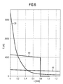
- Figure 6 shows the armature holding force 39, the contact force 40 acting on the fixed contacts, and the spring force of the pressure spring 41 on the rocker as a function of the spacing s between the armature and the cup, illustrated in a measurement graph for the embodiment of the magnetic switch illustrated in Figure 1, in the closed condition.
- the armature holding force 39 is approximately 35 N.
- the armature holding force decreases sharply as the spacing s between the armature and the cup increases, as a result of the weakening of the magnetic field as the operational air gap grows larger.
- the contact force 40 decreases as the spacing s between the armature and the cup increases, although only linearly, in accordance with the force/distance curve of a spring.
- the spring force of the pressure spring 41 decreases linearly with increasing spacing s between the armature and the cup, in accordance with the force/distance curve of a spring. From a spacing s between the armature and the cup of approximately 0.8 mm, the contact is opened, as a result of which the contact force 40 goes down to zero. At this spacing, the armature holding force 39 is still only very small, being still approximately 1 N, as a result of which the armature is held in the opened position by the spring force 41 of the pressure spring.
Landscapes
- Physics & Mathematics (AREA)
- Electromagnetism (AREA)
- Electromagnets (AREA)
Priority Applications (1)
| Application Number | Priority Date | Filing Date | Title |
|---|---|---|---|
| EP01106190A EP1137032A3 (fr) | 2000-03-15 | 2001-03-14 | Interrupteur magnétique |
Applications Claiming Priority (3)
| Application Number | Priority Date | Filing Date | Title |
|---|---|---|---|
| EP00105436 | 2000-03-15 | ||
| EP00105436 | 2000-03-15 | ||
| EP01106190A EP1137032A3 (fr) | 2000-03-15 | 2001-03-14 | Interrupteur magnétique |
Publications (2)
| Publication Number | Publication Date |
|---|---|
| EP1137032A2 true EP1137032A2 (fr) | 2001-09-26 |
| EP1137032A3 EP1137032A3 (fr) | 2003-07-16 |
Family
ID=26070672
Family Applications (1)
| Application Number | Title | Priority Date | Filing Date |
|---|---|---|---|
| EP01106190A Withdrawn EP1137032A3 (fr) | 2000-03-15 | 2001-03-14 | Interrupteur magnétique |
Country Status (1)
| Country | Link |
|---|---|
| EP (1) | EP1137032A3 (fr) |
Cited By (10)
| Publication number | Priority date | Publication date | Assignee | Title |
|---|---|---|---|---|
| CN103311047A (zh) * | 2012-03-07 | 2013-09-18 | 吉林永大电气开关有限公司 | 永磁操动机构 |
| EP3018677A1 (fr) * | 2014-11-06 | 2016-05-11 | Rockwell Automation Technologies, Inc. | Pôle unique, système de commutation de trajet de courant unique et procédé |
| CN106655705A (zh) * | 2016-10-16 | 2017-05-10 | 黄佳宁 | 一种软启动永磁耦合器 |
| US9722513B2 (en) | 2014-11-06 | 2017-08-01 | Rockwell Automation Technologies, Inc. | Torque-based stepwise motor starting |
| US9726726B2 (en) | 2014-11-06 | 2017-08-08 | Rockwell Automation Technologies, Inc. | Single-pole, single current path switching system and method |
| US9748873B2 (en) | 2014-11-06 | 2017-08-29 | Rockwell Automation Technologies, Inc. | 5-pole based wye-delta motor starting system and method |
| US9806641B2 (en) | 2014-11-06 | 2017-10-31 | Rockwell Automation Technologies, Inc. | Detection of electric motor short circuits |
| US9806642B2 (en) | 2014-11-06 | 2017-10-31 | Rockwell Automation Technologies, Inc. | Modular multiple single-pole electromagnetic switching system and method |
| US10074497B2 (en) | 2014-11-06 | 2018-09-11 | Rockwell Automation Technologies, Inc. | Operator coil parameter based electromagnetic switching |
| US10141143B2 (en) | 2014-11-06 | 2018-11-27 | Rockwell Automation Technologies, Inc. | Wear-balanced electromagnetic motor control switching |
Family Cites Families (3)
| Publication number | Priority date | Publication date | Assignee | Title |
|---|---|---|---|---|
| JP2613904B2 (ja) * | 1987-12-23 | 1997-05-28 | 松下電工株式会社 | 有極電磁石 |
| DE4004359A1 (de) * | 1990-02-13 | 1991-08-14 | Kloeckner Moeller Gmbh | Elektromagnetischer schnellausloeser fuer elektrische schaltgeraete |
| US5883557A (en) * | 1997-10-31 | 1999-03-16 | General Motors Corporation | Magnetically latching solenoid apparatus |
-
2001
- 2001-03-14 EP EP01106190A patent/EP1137032A3/fr not_active Withdrawn
Cited By (21)
| Publication number | Priority date | Publication date | Assignee | Title |
|---|---|---|---|---|
| CN103311047A (zh) * | 2012-03-07 | 2013-09-18 | 吉林永大电气开关有限公司 | 永磁操动机构 |
| CN103311047B (zh) * | 2012-03-07 | 2015-05-13 | 吉林永大电气开关有限公司 | 永磁操动机构 |
| US9772381B2 (en) | 2014-11-06 | 2017-09-26 | Rockwell Automation Technologies, Inc. | Synchronized reapplication of power for driving an electric motor |
| US9806641B2 (en) | 2014-11-06 | 2017-10-31 | Rockwell Automation Technologies, Inc. | Detection of electric motor short circuits |
| US10393809B2 (en) | 2014-11-06 | 2019-08-27 | Rockwell Automation Technologies, Inc. | Intelligent timed electromagnetic switching |
| US9722513B2 (en) | 2014-11-06 | 2017-08-01 | Rockwell Automation Technologies, Inc. | Torque-based stepwise motor starting |
| US9726726B2 (en) | 2014-11-06 | 2017-08-08 | Rockwell Automation Technologies, Inc. | Single-pole, single current path switching system and method |
| US9746521B2 (en) | 2014-11-06 | 2017-08-29 | Rockwell Automation Technologies, Inc. | 6-pole based wye-delta motor starting system and method |
| US9748873B2 (en) | 2014-11-06 | 2017-08-29 | Rockwell Automation Technologies, Inc. | 5-pole based wye-delta motor starting system and method |
| US9766291B2 (en) | 2014-11-06 | 2017-09-19 | Rockwell Automation Technologies Inc. | Cleaning and motor heating electromagnetic motor control switching |
| EP3018677A1 (fr) * | 2014-11-06 | 2016-05-11 | Rockwell Automation Technologies, Inc. | Pôle unique, système de commutation de trajet de courant unique et procédé |
| CN105589348A (zh) * | 2014-11-06 | 2016-05-18 | 洛克威尔自动控制技术股份有限公司 | 单极单载流路径开关系统和方法 |
| US9806642B2 (en) | 2014-11-06 | 2017-10-31 | Rockwell Automation Technologies, Inc. | Modular multiple single-pole electromagnetic switching system and method |
| CN105589348B (zh) * | 2014-11-06 | 2018-06-29 | 罗克韦尔自动化技术公司 | 单极单载流路径开关系统和方法 |
| US10018676B2 (en) | 2014-11-06 | 2018-07-10 | Rockwell Automation Technologies, Inc. | Electromagnetic switch interlock system and method |
| US10074497B2 (en) | 2014-11-06 | 2018-09-11 | Rockwell Automation Technologies, Inc. | Operator coil parameter based electromagnetic switching |
| US10101393B2 (en) | 2014-11-06 | 2018-10-16 | Rockwell Automation Technologies, Inc. | Temperature-based electromagnetic switching |
| US10141143B2 (en) | 2014-11-06 | 2018-11-27 | Rockwell Automation Technologies, Inc. | Wear-balanced electromagnetic motor control switching |
| US10175298B2 (en) | 2014-11-06 | 2019-01-08 | Rockwell Automation Technologies, Inc. | Wellness monitoring of electromagnetic switching devices |
| US10361051B2 (en) | 2014-11-06 | 2019-07-23 | Rockwell Automation Technologies, Inc. | Single pole, single current path switching system and method |
| CN106655705A (zh) * | 2016-10-16 | 2017-05-10 | 黄佳宁 | 一种软启动永磁耦合器 |
Also Published As
| Publication number | Publication date |
|---|---|
| EP1137032A3 (fr) | 2003-07-16 |
Similar Documents
| Publication | Publication Date | Title |
|---|---|---|
| US6424244B1 (en) | Magnetic switch | |
| US20240170946A1 (en) | Dropout recloser | |
| JP2745242B2 (ja) | 直流切換装置 | |
| US9275815B2 (en) | Relay having two switches that can be actuated in opposite directions | |
| US4306207A (en) | Self-sustaining solenoid | |
| EP3748662A1 (fr) | Actionneur cinétique pour interrupteur sous vide | |
| CA2569064A1 (fr) | Dispositif de contacts | |
| EP2091061B1 (fr) | Actionneur de déclenchement incluant une traversée thermoplastique, et unité de déclenchement et appareil de commutation électrique l'incluant | |
| US5864274A (en) | Magneto-mechanical power system | |
| EP1137032A2 (fr) | Interrupteur magnétique | |
| KR102531849B1 (ko) | 스위칭 장치 | |
| US12340964B2 (en) | Contact apparatus, electromagnetic switch, onboard charger, and new energy vehicle | |
| CN218385043U (zh) | 继电器 | |
| US3995243A (en) | Fault detection indicator | |
| KR102531475B1 (ko) | 릴레이 | |
| CN218730704U (zh) | 继电器 | |
| ATE46056T1 (de) | Magnetausloeser fuer fehlerstromschutzschalter. | |
| JP2024542832A (ja) | ストッパを有するスイッチングデバイスおよびスイッチングデバイスを作動させる方法 | |
| JP2000299041A (ja) | 真空遮断器 | |
| US20030210117A1 (en) | Magnetic latching contactor | |
| US3848206A (en) | Electromagnetic solenoid with improved contact antibounce means | |
| US5015980A (en) | Solenoid switch apparatus | |
| US3855488A (en) | Push button pulse signal generator | |
| US11631563B2 (en) | Electromagnetic actuator, electrical switching unit comprising an electromagnetic actuator of this kind | |
| CA1224833A (fr) | Relais polaire |
Legal Events
| Date | Code | Title | Description |
|---|---|---|---|
| PUAI | Public reference made under article 153(3) epc to a published international application that has entered the european phase |
Free format text: ORIGINAL CODE: 0009012 |
|
| AK | Designated contracting states |
Kind code of ref document: A2 Designated state(s): AT BE CH CY DE DK ES FI FR GB GR IE IT LI LU MC NL PT SE TR |
|
| AX | Request for extension of the european patent |
Free format text: AL;LT;LV;MK;RO;SI |
|
| PUAL | Search report despatched |
Free format text: ORIGINAL CODE: 0009013 |
|
| AK | Designated contracting states |
Designated state(s): AT BE CH CY DE DK ES FI FR GB GR IE IT LI LU MC NL PT SE TR |
|
| AX | Request for extension of the european patent |
Extension state: AL LT LV MK RO SI |
|
| AKX | Designation fees paid | ||
| REG | Reference to a national code |
Ref country code: DE Ref legal event code: 8566 |
|
| STAA | Information on the status of an ep patent application or granted ep patent |
Free format text: STATUS: THE APPLICATION IS DEEMED TO BE WITHDRAWN |
|
| 18D | Application deemed to be withdrawn |
Effective date: 20040117 |