EP1137044A2 - Flugzeitmassenspektrometer mit auswählbarer Driftlänge - Google Patents
Flugzeitmassenspektrometer mit auswählbarer Driftlänge Download PDFInfo
- Publication number
- EP1137044A2 EP1137044A2 EP01302006A EP01302006A EP1137044A2 EP 1137044 A2 EP1137044 A2 EP 1137044A2 EP 01302006 A EP01302006 A EP 01302006A EP 01302006 A EP01302006 A EP 01302006A EP 1137044 A2 EP1137044 A2 EP 1137044A2
- Authority
- EP
- European Patent Office
- Prior art keywords
- ion
- ions
- drift region
- reflector
- time
- Prior art date
- Legal status (The legal status is an assumption and is not a legal conclusion. Google has not performed a legal analysis and makes no representation as to the accuracy of the status listed.)
- Granted
Links
Images


Classifications
-
- H—ELECTRICITY
- H01—ELECTRIC ELEMENTS
- H01J—ELECTRIC DISCHARGE TUBES OR DISCHARGE LAMPS
- H01J49/00—Particle spectrometers or separator tubes
- H01J49/26—Mass spectrometers or separator tubes
- H01J49/34—Dynamic spectrometers
- H01J49/40—Time-of-flight spectrometers
- H01J49/406—Time-of-flight spectrometers with multiple reflections
Definitions
- This invention relates to time-of-flight mass spectrometers that incorporate an ion mirror or reflector to increase the effective length of the drift region focusing. More particularly it relates to such spectrometers having more than one ion reflector and in which the number of reflections undergone by the ion packets can be varied to adjust the resolution of the spectrometer.
- the mass-to-charge ratio of an ion is determined by accelerating it through to a given energy by means of an electrostatic field and measuring its subsequent flight time through a field-free drift region.
- the mass resolution of such a spectrometer is obviously dependent on the length of the drift region, because increasing its length will increase the separation in time between ions of adjacent mass-to-charge ratios.
- drift region length is in practice limited by the physical size of the spectrometer and certain observations, discussed below, limit the maximum resolution obtainable, irrespective of the drift region length.
- the two most important aberrations arise from: (i) variations in the position in the accelerating field at which the ion is generated; and (ii) variations in the velocity imparted to the ion during its creation.
- the first of these aberrations may be at least in part corrected by the space focusing technique, first taught by Wiley and McLaren in Rev. Sci. Instrum. 1955 vol 26 (12) pp 1150-1157, and in many subsequent papers and patents.
- the second aberration requires correction by velocity focusing.
- the technique known as delayed extraction, also first suggested by Wiley and McLaren (ibid.) is a commonly used method of providing some degree of velocity focusing.
- Another way of reducing the effect of different initial ion velocities is to provide an ion reflector at the end of the drift region to reflect the ions back towards the source through the drift region to a detector located close to the source (see, for example, Mamyrin, Karatev et al, Sov. Phys. JETP, 1973, vol 37 (1) pp 45-48). Ions that leave the source region with a high velocity in the direction of the drift region will penetrate further into the ion reflector before being turned around than will ions of a lower initial velocity. Consequently, ions with high initial velocity will travel a greater distance between the source and the detector than will ions of lower initial velocity. It is therefore possible to arrange the instrumental parameters so that the "initially fast" and the "initially slow” ions arrive at the detector at the same time.
- Another advantage that results from the use of a reflecting analyser is that the distance travelled by the ions in the drift region is approximately double that it would be in a linear analyser of the same physical size, which results in improved resolution.
- each reflection results in a transmission loss (typically between 10% and 50%), and mass peaks tend to be broadened (and therefore reduced in intensity) as the path length is increased.
- the spectrometers described in DE4418489, and US 5,880,466 are essentially ion traps in which a packet of ions is repeatedly reflected between two parallel ion mirrors and does not enter a conventional ion detector. Instead, the oscillating ion packet is caused to induce a signal in sensing electrodes, which signal can be measured and processed by suitable electronic data processing equipment.
- GB 2080021 discloses in its Figure 6 embodiment a multiple reflection time-of-flight mass spectrometer comprising an ion mirror that can be electronically tilted to reflect the incoming ion packets at different angles. At one such angle, the reflected packets pass into an ion detector, thereby enabling a moderate resolution spectrum to be recorded. At another such angle the reflected packets are directed to a second ion mirror and then to another ion detector, thereby providing increased path length and enabling a higher resolution spectrum to be recorded at lower sensitivity.
- Piyadasa detects the ions by switching off one of the mirrors after a predetermined time to allow the ion packets to pass through the mirror and impact on a conventional ion detector.
- the number of ion reflections may be varied by adjustment of the time interval between the generation of an ion packet and the moment the ion mirror is switched off.
- Another objective is to provide such a time-of-flight mass analyser in which the number of reflections can be changed more easily than is possible with prior multiple-reflection spectrometers.
- Other objectives are to provide mass spectrometers and tandem mass spectrometers comprising such time-of-flight mass analysers.
- Another objective is to provide methods of changing the number of reflections in a time-of-flight mass analyser having orthogonal ion injection, which are simpler and more easily implemented than prior methods.
- Further objectives are to provide methods of changing the resolution of a time-of-flight mass analyser having orthogonal ion injection or of a mass spectrometer incorporating such an analyser, which are simpler and more easily implemented than prior methods.
- a time-of-flight mass analyser comprising:
- the ion detector is disposed in a common plane with the ion packet generator at the entrance to the drift region. Preferably, this plane is perpendicular to the axis of the drift region.
- the second ion reflector is disposed between the ion detector and the ion packet generator in another plane which is also perpendicular to the axis of the drift region. Most preferably, the two planes are coincident.
- the length of the path travelled by the packets of ions from the ion packet generator to the ion detector is determined by the value of n . If n is zero, the analyser functions as a conventional reflectron analyser in which ion packets are generated by the ion packet generator and travel through the drift region to the first ion reflector. The first ion reflector then reflects them back through the drift region into the ion detector.
- An analyser according to the invention may operate in this mode if the inclination of the initial direction to the drift region axis is such that the ions reflected by the first ion reflector do not enter the second ion reflector, but instead pass directly into the ion detector.
- ions leaving the ion packet generator travel through the drift region to the first ion reflector where they are reflected back through at least a portion of the drift region and enter the second ion reflector. This returns them to the first ion reflector, which in turn reflects them back through the drift region.
- their displacement from the drift region axis is now greater than it was after the first reflection at the first ion reflector so that they now enter the ion detector instead of the second ion reflector. This mode of operation is described in greater detail below.
- the increase in resolution is accompanied by a loss in sensitivity, however, because each reflection results in some loss of ions, sometimes as much as 50%.
- Preferred embodiments of the invention therefore comprise a time-of-flight analyser which has at least two of these modes of operation, corresponding to at least a low resolution / high sensitivity mode and a high resolution / low sensitivity mode (i.e. a mode with a zero or low value of n , and a mode with a higher value of n ).
- Means are provided for selecting the modes by changing the inclination of the initial direction at which the ions enter the drift region relative to its axis.
- the injection of ions into the drift region is done by intermittently applying an electrostatic field approximately orthogonally to the direction of travel of the beam of ions travelling through the ion packet generator, as in a conventional orthogonal acceleration time-of-flight mass analyser.
- Application of this field ejects a packet of ions comprising a segment of the ion beam into the drift region in an initial direction which is the resultant of the orthogonal velocity imparted to the ions by the field and their original transverse velocity through the ion packet generator.
- the orthogonal component of velocity is typically much greater than their original velocity so that the packet of ions leaves the ion packet generator in the approximate direction of the axis of the drift region, as in a prior orthogonal time-of-flight analyser.
- the initial direction of travel in the drift region and the axis of the drift region determines the mode of operation of the analyser.
- a high angle of inclination between the actual initial direction and the axis of the drift region results in a low (or zero) value of n , while a low angle gives a higher value of n .
- the initial direction and consequently the value of n with which the time-of-flight analyser operates, is determined by the ratio of the initial velocity of the ions as they enter the ion packet generator to the orthogonal velocity imparted to them in the ion packet generator.
- a desired mode of operation is selected by setting the ratio of the initial energy at which the ions enter the ion packet generator to the orthogonal energy imparted to the ions by the ion packet generator to the value which results in the desired value of n .
- the energy of the ions entering the ion packet generator is controlled by accelerating the ions through a potential gradient as they approach the ion packet generator so that they enter it with an energy equal to the sum of their starting energy and the energy they acquire on travelling through the gradient.
- the starting energy of each of the ions entering the ion packet generator must be similar. This is most conveniently achieved by use of an ion energy-collimating device upstream of the ion packet generator.
- Such devices include (without limitation thereto) a collisional-focusing gas cell and an electrostatic energy filter.
- a collisional-focusing gas cell causes the ions passing through it to repeatedly collide with molecules of an inert gas in the cell so that they emerge with a kinetic energy approximately equal to that of the thermal energy of the neutral gas molecules, irrespective of their original kinetic energy.
- Such devices are well known in the art, and are described, for example, in US patent 4,963,736.
- they may comprise a multipole electrode set to which radio frequency potentials are applied to confine the ions to the vicinity of the cell axis, and into which an inert gas at a pressure of about 10 -2 torr is introduced.
- Such a cell produces a beam of ions which comprises ions having approximately the same kinetic energy (usually less than about 3eV) and which are all travelling in the same direction.
- a preferred embodiment of the invention may therefore comprise a mass spectrometer which has an ion source, a collisional-focusing gas cell for collimating the ions generated by the source, equalizing their kinetic energies and transmitting them to a time-of-flight mass analyser of the type previously described.
- the invention may comprise a tandem mass spectrometer which has an ion source, a first mass filter for transmitting ions having mass-to-charge ratios in a predetermined range, a collisional-focusing gas cell for receiving ions transmitted by said first mass filter, fragmenting them by collisions with neutral molecules of gas, collimating said fragment ions, equalizing their kinetic energies and transmitting them to a time-of-flight mass analyser of the type previously described.
- the first mass analyser will comprise a linear quadrupole mass filter or a quadrupole ion trap. It is also within the scope of the invention to combine the gas cell with the first mass analyser, particularly in the case of a quadrupole ion trap.
- the mode of operation of the time-of-flight analyser i.e. the value of n
- the mode of operation of the time-of-flight analyser can be changed merely by adjusting the value of the potential gradient through which the ions are accelerated as they approach the ion packet generator. This is much simpler way of changing the number of reflections in a multiple reflection time-of-flight analyser than is taught by any of the prior art discussed above.
- the invention provides a method of determining the mass-to-charge ratio of ions travelling in a beam by measuring their time of flight through a drift region having an axis, an entrance and an exit, there being also provided a first ion reflector disposed at said exit and a second ion reflector disposed in juxtaposition to said first ion reflector to reflect those packets of ions which enter it back through at least a portion of said drift region; said method comprising sequentially executing the following steps: -
- the invention provides a simple and convenient method of changing between these modes, merely by adjusting the angle of inclination between the initial direction at which the ions enter the drift region and the axis of the drift region.
- the initial direction in which the ions are injected into the drift region, and therefore the value of n is dependent on the ratio of the energy imparted by the electrostatic field to the ions in the beam to inject packets of ions into the drift region and the original energy they possessed while travelling in the beam.
- a desired mode of operation is selected by setting the ratio of the initial energy of the ions in the beam from which the ion packets are ejected to the energy imparted to them by the electrostatic field to the value which results in the desired value of n .
- the electrostatic field is arranged to eject the ion packets from the beam in a substantially orthogonal direction.
- the energy of ions in the beam is controlled by accelerating them through a potential gradient before the electrostatic field is applied to eject packets of ions into the drift region.
- the desired value of n may then be selected simply by adjusting the potential difference through which the ions are accelerated.
- the ions are passed through an ion energy-collimating device before they are accelerated by the potential gradient.
- Such devices include (without limitation thereto) a collisional-focusing gas cell and an electrostatic energy filter. This ensures that the ions have substantially the same energy at the moment that they are injected into the drift region, so that the initial direction in the drift region is the same for all ions in any given packet of ions.
- the invention further provides a method of mass spectrometry comprising generating a beam of ions whose mass-to-charge ratios are to be determined, passing said beam through a collisional-focusing gas cell in order to collimate the ions and to equalize their translational energies, and determining their mass-to-charge ratios by measuring their time of flight through a drift region in the manner described above.
- the invention further provides a method of tandem mass spectrometry comprising generating a beam of ions, passing said ions through a first mass filter to transmit only those ions having mass-to-charge ratios in a predetermined range, fragmenting at least some of those ions by collisions with molecules of inert gas, collimating the fragment ions and equalizing their translational energies, and determining the mass-to-charge ratios of the fragment ions by measuring their time of flight through a drift region in the manner described above.
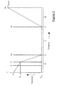
- a time-of-flight mass analyser generally indicated by 1 comprises a drift region 2 having an axis 3, an entrance 4 and an exit 5.
- An ion-packet generator 6 comprises a pusher electrode 7 and three extraction grids 8, 9 and 10.
- a first ion reflector 18 is disposed downstream of the exit 5, and a second ion reflector 19 is disposed at the entrance 4.
- An ion detector 20 is also disposed at the entrance 4, as shown.
- the analyser is enclosed in a vacuum housing (shown schematically at 17) and maintained at a pressure of 10 -6 torr or less by a suitable pumping system (not shown).
- a beam of ions whose mass-to-charge ratio is to be determined enters the ion-packet generator 6 along a beam axis 11 and passes between the pusher electrode 7 and the first extraction grid 8.
- a beam collection electrode 12 receives ions that are not injected into the drift region by the ion packet generator 6, and deflects them into an auxiliary ion detector 13. The detector may be used to monitor the incoming ion beam and to adjust the apparatus used to generate that beam without using the time-of-flight analyser itself.
- the drift region 2 is enclosed by a conductive flight tube 14. This is mounted at the entrance 4 of the drift region 2 from an insulating flange 15 that is fitted into a recess in the vacuum housing 17. A conductive flange 21, maintained at the same potential as the flight tube 14, is also attached to the flange 15. At the exit 5, the end of the flight tube 14 is supported from a flange 22 by ceramic rods 16 that form part of the first ion reflector 18.
- the first ion reflector 18 comprises 11 annular electrodes 23-33 and a rear reflector electrode 34, all supported on the ceramic rods 16 and spaced apart by tubular ceramic insulators (eg, 35 and 36). Electrode 23 additionally comprises a fine mesh entrance grid, represented by a dashed line in Fig. 1.
- the second ion reflector 19 comprises five annular reflector electrodes 37-41 and a rear reflector electrode 42, each mounted on ceramic rods 43, 44 and spaced apart by tubular insulators 46.
- a fine mesh entrance grid 55, attached to the flange 21, is also provided.
- the ion detector 20 comprises two microchannel plate electron multiplier plates 47 in series.
- a collector electrode 73 is disposed behind the multiplier plates 47 to receive the secondary electrons generated by the multiplier plates 47 and is capacitively coupled to a plate electrode 48.
- the dielectric material of the capacitor formed by electrodes 73 and 48 is a polyimide film 72 that is capable of providing electrical isolation to at least 8KV.
- a 50-ohm transmission line comprising a solid inner conical member 49 and an outer conical member 50 are used to connect the electrode 48 to a RF coaxial connector 51 mounted on the vacuum housing 17.
- Accurate impedance matching of the electrical connection to the collector electrode 48 is important because the frequency response of the detector and its associated electronics must be in the GHz region to allow the time-of-flight analyser to operate at maximum sensitivity and resolution.
- the electrical insulation provided by the film 72 allows the detector to respond to both positive and negative ions. In order to detect negative ions it is necessary to maintain the electrode 73 at a high potential, and the presence of the film 72 allows the conical member 49 and the connector 51 to be maintained at ground potential. This facilitates the connection of the ion detector signal processing equipment while maintaining the required potential difference across the microchannel plates 48.
- ion detector 20, first reflector 18, drift region 2 and the ion-packet generator 6 are conventional components of prior orthogonal acceleration mass analysers and need not be described in detail.
- ions entering the ion-packet generator 6 do so between the pusher electrode 7 and the first extractor grid 8 at a potential V IN , which is typically a few volts removed from ground potential.
- the pusher electrode 7 and extractor grids 8 and 9 are maintained at the potential V IN .
- the extractor grid 10 and the flight tube 14 are maintained at a high potential V TOF , which is typically -9 kV for use with positive ions, and +9 kV for use with negative ions.
- the grid 23 at the entrance of the first ion reflector 18 is also maintained at V TOF , ensuring that the drift region 2 remains field free.
- V REFLECT is typically about 2.5 kV higher than V IN (i.e. +2.5 kV for positive ions,-2.5 kV for negative ions). Consequently, ions entering the first ion reflector 18 are reflected before they strike the rear reflector electrode 34, as shown by the trajectories 52-54 (Fig. 1).
- the entrance of the ion detector microchannel plates 48 is maintained at the flight tube potential V TOF .
- the potential of the pusher electrode 7 is momentarily raised to V P (typically about 1.5 kV higher than V IN ) and the potential of the extraction grid 8 is simultaneously set to an intermediate value such that an approximately linear potential gradient is generated in the ion-packet generator 6.
- V P typically about 1.5 kV higher than V IN
- the potential of the extraction grid 8 is simultaneously set to an intermediate value such that an approximately linear potential gradient is generated in the ion-packet generator 6.
- Application of this ion ejection pulse causes the ions comprised in the segment of the ion beam present inside the ion-packet generator 6 to be injected into the drift region 2 at the entrance 4.
- this packet of ions travels through the drift region 2 along trajectory 53 and is reflected by the first ion reflector 18 back through the drift region 2 to reach the ion detector 20.
- the ions comprised in the packet separate according to their mass-to-charge ratios so that the lightest ions (having high velocities) reach the detector in advance of the heavier ions.
- a mass spectrum can therefore be recorded by measuring the time of arrival of the ions at the detector. This mode of operation (i.e.
- the present invention additionally incorporates a second ion reflector 19 (Fig. 1) which is used when greater resolution is required.
- a second ion reflector 19 Fig. 1 which is used when greater resolution is required.
- the potential difference between the rear reflector electrode 42 of the second ion reflector 19 and its first reflecting electrode 55 may be the same as that applied across the first ion reflector 18 because they both reflect ions having the same kinetic energy. Consequently, the same high voltage power supply can be used to supply both reflectors.
- no other major components are required to modify a conventional orthogonal reflection type analyser to a selectable resolution analyser according to the invention.
- Fig. 5 illustrates the ion trajectories in a still higher resolution mode of operation, in which the ions make six passes through the drift region.
- the trajectory of the ions in this mode may be compared with the trajectories 54 and 53 shown in Fig. 1 four-pass and two-pass modes, respectively.
- the second ion reflector 19 is smaller and simpler in construction than the first ion reflector 18 because it needs only to reflect the ion packets.
- the first reflector 18 must also provide spatial focusing.
- the beam of ions travelling along the beam axis 11 is of significant width relative to the distance between the pusher electrode 7 and the extractor grid 9. Consequently, ions starting from different positions on either side of the axis 11 will be accelerated through different potential gradients when the extraction pulse is applied (V P , Fig. 2). Unless properly compensated, this effect seriously reduces mass resolution.
- the first reflector 18 can be arranged to compensate the effect if its potential gradient is properly selected.
- the reflector is arranged to provide spatial focusing so that ions of a given mass-to-charge ratio having greater than average kinetic energy travel further into the reflector before being turned around and arrive back at the entrance 4 of the drift region at exactly the same time as ions having lower energies. Ions of lower energy travel less far into the reflector before being turned around. Spatial focusing is achieved when the greater distance travelled by the fast ions exactly compensates the excess energy they acquired by virtue of their displaced starting position in the ejection field in the ion-packet generator.
- the second ion reflector 19 is not required to provide spatial focusing and may therefore be uncritical in construction and size. This effect greatly facilitates construction of an analyser according to the invention, allowing the second ion reflector 19 to be small enough to be fitted between the ion-packet generator and the ion detector 20 in an analyser optimized for two-pass operation (ie, the second mode), without affecting performance in that mode.
- the second ion reflector should be disposed in the same plane as the ion packet generator 6 and detector 20, as shown in Fig. 1.
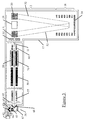
- a tandem mass spectrometer comprises an atmospheric pressure ionization source generally indicated by 56, a first multi-polar ion guide 57, a quadrupole mass analyser 58, a multi-polar collision cell 59 and second multi-polar ion guide 60.
- An electrostatic lens 61 is provided to transmit ions leaving the ion guide 60 into the ion packet generator 6 of a time-of-flight analyser of the type described above.
- a tandem mass spectrometer comprising the components 56-61 and a conventional prior type of time-of-flight mass analyser downstream of the electrostatic lens 61 is commercially available from Micromass UK Ltd as the "Q-TOF" mass spectrometer. Only a brief description of the construction and method of operation of the components 56-61 is therefore necessary.
- a solution containing a sample to be analysed is introduced into a capillary tube comprised in a sample introduction probe 62 to produce an aerosol 63 at atmospheric pressure in the chamber 64.
- Ions in the aerosol 63 are sampled through a nozzle 65 and pass through an isolation valve 66 into an evacuated chamber 67, from which they pass through nozzles 68 and 69 to the ion guide 57.
- Ion guide 57 collimates and thermalises the ions and transmits them in turn to the quadrupole mass analyser 58 which allows ions of a predetermined range of mass-to-charge ratios to reach the multi-polar collision cell 59.
- At least some of the ions transmitted from the first quadrupole analyser 58 may be fragmented by collisions with inert gas molecules.
- An enclosure 70 surrounds the cell 59 to maintain the pressure of inert gas introduced into it in the range 10 -3 to 10 -2 torr.
- a second multi-polar ion guide 60 then transmits the ions emerging from the collision cell 59 through the lens 61 into the ion packet generator 6 of a time-of-flight analyser of the type illustrated in Fig. 1.
- the spectrometer of Fig. 3 can be used without fragmenting ions in the collision cell 59 by operating the cell 59 as an ion guide without introducing an inert gas. A beam of unfragmented ions may then be transmitted directly to the ion packet generator 6. Mass analyser 58 may of course be set to transmit ions of any desired mass range to the ion-packet generator 6.
- the ion guide 58 should be operated at a sufficient pressure (about 10 -2 torr) to ensure that the ions entering the ion packet generator 6 are adequately thermalised.
- the mode of operation of the time-of-flight analyser incorporated in the spectrometer of Fig. 3 is determined by the initial direction relative to the axis 3 (Fig. 1) in which packets of ions leave the ion packet generator 6.
- This initial direction is the resultant of the electrostatic field applied to the ions in the ion packet generator to inject them into the drift region entrance 4 and their original kinetic energy along the beam axis 11.
- the ion guide 57 and/or the collision cell 59 and ion guide 60 produce a highly collimated ion beam along the axis 11 in which the ions have a very small spread in energy.
- the initial direction at which the packets leave the ion packet generator 6, and hence value of n may therefore be determined by setting the energy at which the ions enter the ion packet generator 6. In the spectrometer of Fig. 3 this is done by maintaining a suitable accelerating potential between the last element of the electrostatic lens 61 and the ion packet generator 6, as shown in Fig. 4. Thus, if a first potential (typically about -20 V) is selected by the switch 71 (Fig. 4), ions enter the packet generator 6 with approximately 20 eV energy. A potential difference of approximately 11 kV is maintained between the grid 9 and grid 10 and the flight tube 14 (V TOF , Fig.
- V REFLECT V REFLECT , Fig. 2
- ion packets are injected by raising the potential of the pusher electrode 7 above that of the grid 9 by V P (Fig. 2) and the grid 8 to an intermediate value.
- V P is approximately 1.5 kV.
- ion packets leave the ion packet generator 6 in directions exemplified by 52 (Fig. 1) and are reflected first by the first ion reflector 18, then by the second ion reflector 19.
- the switch 71 is set to apply approximately -60 volts between the lens 61 and the ion-packet generator 6.
- the greater kinetic energy then possessed by the ions causes the ion packets to exit from the ion-packet generator 6 along trajectories exemplified by 53.
- These trajectories are inclined at a steeper angle to the drift region axis 3 than the trajectories 52 because of the greater component of velocity possessed by the ions in a direction perpendicular to the axis 3. Consequently, on reflection by the first ion mirror 18 they are returned directly to the detector 20, making only two passes through the drift region 2.
- a mass resolution of 15,000 is typical for a drift region length of 0.5 m.
- n 0
- the power supply that supplies the V REFLECT voltage for the first ion reflector 18 can also be used to supply the second ion reflector 19. It will be appreciated, therefore, that the invention provides a very simple way of providing a compact switchable resolution time-of-flight mass analyser involving merely the switching of a single low potential (and optionally two other potentials in the case of a high-performance analyser), which is cheaper to manufacture than any prior multiple-reflection time-of-flight spectrometer.
Landscapes
- Chemical & Material Sciences (AREA)
- Analytical Chemistry (AREA)
- Electron Tubes For Measurement (AREA)
- Other Investigation Or Analysis Of Materials By Electrical Means (AREA)
Applications Claiming Priority (4)
| Application Number | Priority Date | Filing Date | Title |
|---|---|---|---|
| GB0005125A GB0005125D0 (en) | 2000-03-03 | 2000-03-03 | Time of flight mass spectrometer with selectable drift length |
| GB0005125 | 2000-03-03 | ||
| GB0013931 | 2000-06-08 | ||
| GB0013931A GB0013931D0 (en) | 2000-03-03 | 2000-06-08 | Time of flight mass spectrometer with selectable drift length |
Publications (3)
| Publication Number | Publication Date |
|---|---|
| EP1137044A2 true EP1137044A2 (de) | 2001-09-26 |
| EP1137044A3 EP1137044A3 (de) | 2005-09-14 |
| EP1137044B1 EP1137044B1 (de) | 2007-05-16 |
Family
ID=26243788
Family Applications (1)
| Application Number | Title | Priority Date | Filing Date |
|---|---|---|---|
| EP01302006A Expired - Lifetime EP1137044B1 (de) | 2000-03-03 | 2001-03-05 | Flugzeitmassenspektrometer mit auswählbarer Driftlänge |
Country Status (7)
| Country | Link |
|---|---|
| US (1) | US6570152B1 (de) |
| EP (1) | EP1137044B1 (de) |
| JP (1) | JP4817513B2 (de) |
| AT (1) | ATE362649T1 (de) |
| CA (1) | CA2339314C (de) |
| DE (1) | DE60128419T2 (de) |
| GB (1) | GB2361580B (de) |
Cited By (38)
| Publication number | Priority date | Publication date | Assignee | Title |
|---|---|---|---|---|
| KR20040034252A (ko) * | 2002-10-21 | 2004-04-28 | 삼성전자주식회사 | 매질 보조 레이저 탈착 여기 비행시간 질량분석기 |
| GB2403063A (en) * | 2003-06-21 | 2004-12-22 | Anatoli Nicolai Verentchikov | Time of flight mass spectrometer employing a plurality of lenses focussing an ion beam in shift direction |
| WO2005114705A3 (en) * | 2004-05-21 | 2006-10-05 | Craig M Whitehouse | Rf surfaces and rf ion guides |
| WO2013045428A1 (en) * | 2011-09-30 | 2013-04-04 | Thermo Fisher Scientific (Bremen) Gmbh | Method and apparatus for mass spectrometry |
| WO2018073589A1 (en) * | 2016-10-19 | 2018-04-26 | Micromass Uk Limited | Dual mode mass spectrometer |
| WO2019215428A1 (en) * | 2018-05-10 | 2019-11-14 | Micromass Uk Limited | Multi-reflecting time of flight mass analyser |
| WO2019215429A1 (en) * | 2018-05-10 | 2019-11-14 | Micromass Uk Limited | Multi-reflecting time of flight mass analyser |
| GB2576076A (en) * | 2018-05-31 | 2020-02-05 | Micromass Ltd | Bench-top time of flight mass spectrometer |
| US10593533B2 (en) | 2015-11-16 | 2020-03-17 | Micromass Uk Limited | Imaging mass spectrometer |
| US10629425B2 (en) | 2015-11-16 | 2020-04-21 | Micromass Uk Limited | Imaging mass spectrometer |
| US10636646B2 (en) | 2015-11-23 | 2020-04-28 | Micromass Uk Limited | Ion mirror and ion-optical lens for imaging |
| US10741376B2 (en) | 2015-04-30 | 2020-08-11 | Micromass Uk Limited | Multi-reflecting TOF mass spectrometer |
| US10950425B2 (en) | 2016-08-16 | 2021-03-16 | Micromass Uk Limited | Mass analyser having extended flight path |
| US11049712B2 (en) | 2017-08-06 | 2021-06-29 | Micromass Uk Limited | Fields for multi-reflecting TOF MS |
| US11081332B2 (en) | 2017-08-06 | 2021-08-03 | Micromass Uk Limited | Ion guide within pulsed converters |
| US11205568B2 (en) | 2017-08-06 | 2021-12-21 | Micromass Uk Limited | Ion injection into multi-pass mass spectrometers |
| US11211238B2 (en) | 2017-08-06 | 2021-12-28 | Micromass Uk Limited | Multi-pass mass spectrometer |
| US11239067B2 (en) | 2017-08-06 | 2022-02-01 | Micromass Uk Limited | Ion mirror for multi-reflecting mass spectrometers |
| US11295944B2 (en) | 2017-08-06 | 2022-04-05 | Micromass Uk Limited | Printed circuit ion mirror with compensation |
| US11309175B2 (en) | 2017-05-05 | 2022-04-19 | Micromass Uk Limited | Multi-reflecting time-of-flight mass spectrometers |
| US11328920B2 (en) | 2017-05-26 | 2022-05-10 | Micromass Uk Limited | Time of flight mass analyser with spatial focussing |
| US11355331B2 (en) | 2018-05-31 | 2022-06-07 | Micromass Uk Limited | Mass spectrometer |
| US11367608B2 (en) | 2018-04-20 | 2022-06-21 | Micromass Uk Limited | Gridless ion mirrors with smooth fields |
| US11367607B2 (en) | 2018-05-31 | 2022-06-21 | Micromass Uk Limited | Mass spectrometer |
| US11373849B2 (en) | 2018-05-31 | 2022-06-28 | Micromass Uk Limited | Mass spectrometer having fragmentation region |
| US11437226B2 (en) | 2018-05-31 | 2022-09-06 | Micromass Uk Limited | Bench-top time of flight mass spectrometer |
| US11476103B2 (en) | 2018-05-31 | 2022-10-18 | Micromass Uk Limited | Bench-top time of flight mass spectrometer |
| WO2022238953A3 (en) * | 2021-05-14 | 2022-12-22 | Dh Technologies Development Pte. Ltd. | Ion mirror for time-of-flight mass spectrometer |
| US11538676B2 (en) | 2018-05-31 | 2022-12-27 | Micromass Uk Limited | Mass spectrometer |
| US11587779B2 (en) | 2018-06-28 | 2023-02-21 | Micromass Uk Limited | Multi-pass mass spectrometer with high duty cycle |
| US11621154B2 (en) | 2018-05-31 | 2023-04-04 | Micromass Uk Limited | Bench-top time of flight mass spectrometer |
| GB2612703A (en) * | 2017-05-05 | 2023-05-10 | Micromass Ltd | Multi-reflecting Time-of-Flight mass spectrometers |
| US11817303B2 (en) | 2017-08-06 | 2023-11-14 | Micromass Uk Limited | Accelerator for multi-pass mass spectrometers |
| US11848185B2 (en) | 2019-02-01 | 2023-12-19 | Micromass Uk Limited | Electrode assembly for mass spectrometer |
| US11881387B2 (en) | 2018-05-24 | 2024-01-23 | Micromass Uk Limited | TOF MS detection system with improved dynamic range |
| US11879470B2 (en) | 2018-05-31 | 2024-01-23 | Micromass Uk Limited | Bench-top time of flight mass spectrometer |
| US12009193B2 (en) | 2018-05-31 | 2024-06-11 | Micromass Uk Limited | Bench-top Time of Flight mass spectrometer |
| US12205813B2 (en) | 2019-03-20 | 2025-01-21 | Micromass Uk Limited | Multiplexed time of flight mass spectrometer |
Families Citing this family (22)
| Publication number | Priority date | Publication date | Assignee | Title |
|---|---|---|---|---|
| US6777671B2 (en) * | 2001-04-10 | 2004-08-17 | Science & Engineering Services, Inc. | Time-of-flight/ion trap mass spectrometer, a method, and a computer program product to use the same |
| JP3990889B2 (ja) * | 2001-10-10 | 2007-10-17 | 株式会社日立ハイテクノロジーズ | 質量分析装置およびこれを用いる計測システム |
| DE10156604A1 (de) * | 2001-11-17 | 2003-05-28 | Bruker Daltonik Gmbh | Raumwinkelfokussierender Reflektor für Flugzeitmassenspektrometer |
| JP4688504B2 (ja) * | 2005-01-11 | 2011-05-25 | 日本電子株式会社 | タンデム飛行時間型質量分析装置 |
| US7351958B2 (en) * | 2005-01-24 | 2008-04-01 | Applera Corporation | Ion optics systems |
| JP4553782B2 (ja) * | 2005-04-12 | 2010-09-29 | 日本電子株式会社 | 飛行時間型質量分析計 |
| CN107833823B (zh) * | 2005-10-11 | 2021-09-17 | 莱克公司 | 具有正交加速的多次反射飞行时间质谱仪 |
| GB0624677D0 (en) * | 2006-12-11 | 2007-01-17 | Shimadzu Corp | A co-axial time-of-flight mass spectrometer |
| GB0624679D0 (en) * | 2006-12-11 | 2007-01-17 | Shimadzu Corp | A time-of-flight mass spectrometer and a method of analysing ions in a time-of-flight mass spectrometer |
| US7589319B2 (en) * | 2007-05-01 | 2009-09-15 | Virgin Instruments Corporation | Reflector TOF with high resolution and mass accuracy for peptides and small molecules |
| WO2009023361A2 (en) | 2007-06-01 | 2009-02-19 | Purdue Research Foundation | Discontinuous atmospheric pressure interface |
| JP5049174B2 (ja) * | 2008-03-21 | 2012-10-17 | 浜松ホトニクス株式会社 | 飛行時間型質量分析装置及びそれに用いられる荷電粒子検出装置 |
| GB0813777D0 (en) | 2008-07-28 | 2008-09-03 | Micromass Ltd | Mass spectrometer |
| GB2496991B (en) | 2010-11-26 | 2015-05-20 | Thermo Fisher Scient Bremen | Method of mass selecting ions and mass selector |
| FR2971360B1 (fr) | 2011-02-07 | 2014-05-16 | Commissariat Energie Atomique | Micro-reflectron pour spectrometre de masse a temps de vol |
| EP2795664B1 (de) * | 2011-12-23 | 2025-05-14 | DH Technologies Development Pte. Ltd. | Fokussierung erster und zweiter ordnung mit hilfe von freifeldregionen bei flugzeitmassenspektrometrie |
| US8933397B1 (en) | 2012-02-02 | 2015-01-13 | University of Northern Iowa Research Foundati | Ion trap mass analyzer apparatus, methods, and systems utilizing one or more multiple potential ion guide (MPIG) electrodes |
| US20160018368A1 (en) | 2013-02-15 | 2016-01-21 | Aldan Asanovich Sapargaliyev | Mass spectrometry method and devices |
| GB201812329D0 (en) | 2018-07-27 | 2018-09-12 | Verenchikov Anatoly | Improved ion transfer interace for orthogonal TOF MS |
| US11566046B2 (en) | 2019-06-07 | 2023-01-31 | Purdue Research Foundation | CBX8 chromdomain inhibitors and the uses thereof |
| JP7409260B2 (ja) | 2020-08-19 | 2024-01-09 | 株式会社島津製作所 | 質量分析方法及び質量分析装置 |
| CN112201562B (zh) * | 2020-11-04 | 2024-11-19 | 肖洋 | 飞行时间质谱仪检测室 |
Family Cites Families (13)
| Publication number | Priority date | Publication date | Assignee | Title |
|---|---|---|---|---|
| DE3025764C2 (de) | 1980-07-08 | 1984-04-19 | Hermann Prof. Dr. 6301 Fernwald Wollnik | Laufzeit-Massenspektrometer |
| JPS6229049A (ja) * | 1985-07-31 | 1987-02-07 | Hitachi Ltd | 質量分析計 |
| WO1989006044A1 (en) | 1987-12-24 | 1989-06-29 | Unisearch Limited | Mass spectrometer |
| SU1725289A1 (ru) * | 1989-07-20 | 1992-04-07 | Институт Ядерной Физики Ан Казсср | Врем пролетный масс-спектрометр с многократным отражением |
| US5202563A (en) | 1991-05-16 | 1993-04-13 | The Johns Hopkins University | Tandem time-of-flight mass spectrometer |
| US5401962A (en) | 1993-06-14 | 1995-03-28 | Ferran Scientific | Residual gas sensor utilizing a miniature quadrupole array |
| US5689111A (en) * | 1995-08-10 | 1997-11-18 | Analytica Of Branford, Inc. | Ion storage time-of-flight mass spectrometer |
| DE4408489C2 (de) | 1994-03-14 | 1997-07-31 | Frank Dr Strehle | Massenspektrometer |
| US5880466A (en) | 1997-06-02 | 1999-03-09 | The Regents Of The University Of California | Gated charged-particle trap |
| JPH11135060A (ja) * | 1997-10-31 | 1999-05-21 | Jeol Ltd | 飛行時間型質量分析計 |
| US6013913A (en) | 1998-02-06 | 2000-01-11 | The University Of Northern Iowa | Multi-pass reflectron time-of-flight mass spectrometer |
| GB2339958B (en) * | 1998-07-17 | 2001-02-21 | Genomic Solutions Ltd | Time-of-flight mass spectrometer |
| GB2403063A (en) * | 2003-06-21 | 2004-12-22 | Anatoli Nicolai Verentchikov | Time of flight mass spectrometer employing a plurality of lenses focussing an ion beam in shift direction |
-
2000
- 2000-06-15 US US09/594,022 patent/US6570152B1/en not_active Expired - Lifetime
-
2001
- 2001-03-02 CA CA002339314A patent/CA2339314C/en not_active Expired - Lifetime
- 2001-03-05 JP JP2001060029A patent/JP4817513B2/ja not_active Expired - Fee Related
- 2001-03-05 GB GB0105386A patent/GB2361580B/en not_active Expired - Lifetime
- 2001-03-05 DE DE60128419T patent/DE60128419T2/de not_active Expired - Lifetime
- 2001-03-05 EP EP01302006A patent/EP1137044B1/de not_active Expired - Lifetime
- 2001-03-05 AT AT01302006T patent/ATE362649T1/de not_active IP Right Cessation
Cited By (52)
| Publication number | Priority date | Publication date | Assignee | Title |
|---|---|---|---|---|
| KR20040034252A (ko) * | 2002-10-21 | 2004-04-28 | 삼성전자주식회사 | 매질 보조 레이저 탈착 여기 비행시간 질량분석기 |
| GB2403063A (en) * | 2003-06-21 | 2004-12-22 | Anatoli Nicolai Verentchikov | Time of flight mass spectrometer employing a plurality of lenses focussing an ion beam in shift direction |
| WO2005114705A3 (en) * | 2004-05-21 | 2006-10-05 | Craig M Whitehouse | Rf surfaces and rf ion guides |
| US7786435B2 (en) | 2004-05-21 | 2010-08-31 | Perkinelmer Health Sciences, Inc. | RF surfaces and RF ion guides |
| WO2013045428A1 (en) * | 2011-09-30 | 2013-04-04 | Thermo Fisher Scientific (Bremen) Gmbh | Method and apparatus for mass spectrometry |
| US9209005B2 (en) | 2011-09-30 | 2015-12-08 | Thermo Fisher Scientific (Bremen) Gmbh | Method and apparatus for mass spectrometry |
| GB2495127B (en) * | 2011-09-30 | 2016-10-19 | Thermo Fisher Scient (Bremen) Gmbh | Method and apparatus for mass spectrometry |
| US10186411B2 (en) | 2011-09-30 | 2019-01-22 | Thermo Fisher Scientific (Bremen) Gmbh | Method and apparatus for mass spectrometry |
| US10741376B2 (en) | 2015-04-30 | 2020-08-11 | Micromass Uk Limited | Multi-reflecting TOF mass spectrometer |
| US10629425B2 (en) | 2015-11-16 | 2020-04-21 | Micromass Uk Limited | Imaging mass spectrometer |
| US10593533B2 (en) | 2015-11-16 | 2020-03-17 | Micromass Uk Limited | Imaging mass spectrometer |
| US10636646B2 (en) | 2015-11-23 | 2020-04-28 | Micromass Uk Limited | Ion mirror and ion-optical lens for imaging |
| US10950425B2 (en) | 2016-08-16 | 2021-03-16 | Micromass Uk Limited | Mass analyser having extended flight path |
| US11094521B2 (en) | 2016-10-19 | 2021-08-17 | Micromass Uk Limited | Dual mode mass spectrometer |
| WO2018073589A1 (en) * | 2016-10-19 | 2018-04-26 | Micromass Uk Limited | Dual mode mass spectrometer |
| GB2612703A (en) * | 2017-05-05 | 2023-05-10 | Micromass Ltd | Multi-reflecting Time-of-Flight mass spectrometers |
| GB2567794B (en) * | 2017-05-05 | 2023-03-08 | Micromass Ltd | Multi-reflecting time-of-flight mass spectrometers |
| GB2612703B (en) * | 2017-05-05 | 2023-08-09 | Micromass Ltd | Multi-reflecting Time-of-Flight mass spectrometers |
| US11309175B2 (en) | 2017-05-05 | 2022-04-19 | Micromass Uk Limited | Multi-reflecting time-of-flight mass spectrometers |
| US11328920B2 (en) | 2017-05-26 | 2022-05-10 | Micromass Uk Limited | Time of flight mass analyser with spatial focussing |
| US11049712B2 (en) | 2017-08-06 | 2021-06-29 | Micromass Uk Limited | Fields for multi-reflecting TOF MS |
| US11205568B2 (en) | 2017-08-06 | 2021-12-21 | Micromass Uk Limited | Ion injection into multi-pass mass spectrometers |
| US11211238B2 (en) | 2017-08-06 | 2021-12-28 | Micromass Uk Limited | Multi-pass mass spectrometer |
| US11239067B2 (en) | 2017-08-06 | 2022-02-01 | Micromass Uk Limited | Ion mirror for multi-reflecting mass spectrometers |
| US11295944B2 (en) | 2017-08-06 | 2022-04-05 | Micromass Uk Limited | Printed circuit ion mirror with compensation |
| US11817303B2 (en) | 2017-08-06 | 2023-11-14 | Micromass Uk Limited | Accelerator for multi-pass mass spectrometers |
| US11756782B2 (en) | 2017-08-06 | 2023-09-12 | Micromass Uk Limited | Ion mirror for multi-reflecting mass spectrometers |
| US11081332B2 (en) | 2017-08-06 | 2021-08-03 | Micromass Uk Limited | Ion guide within pulsed converters |
| US11367608B2 (en) | 2018-04-20 | 2022-06-21 | Micromass Uk Limited | Gridless ion mirrors with smooth fields |
| GB2575157B (en) * | 2018-05-10 | 2022-05-18 | Micromass Ltd | Multi-reflecting time of flight mass analyser |
| GB2575157A (en) * | 2018-05-10 | 2020-01-01 | Micromass Ltd | Multi-reflecting time of flight mass analyser |
| US11342175B2 (en) | 2018-05-10 | 2022-05-24 | Micromass Uk Limited | Multi-reflecting time of flight mass analyser |
| WO2019215428A1 (en) * | 2018-05-10 | 2019-11-14 | Micromass Uk Limited | Multi-reflecting time of flight mass analyser |
| WO2019215429A1 (en) * | 2018-05-10 | 2019-11-14 | Micromass Uk Limited | Multi-reflecting time of flight mass analyser |
| US11621156B2 (en) | 2018-05-10 | 2023-04-04 | Micromass Uk Limited | Multi-reflecting time of flight mass analyser |
| US11881387B2 (en) | 2018-05-24 | 2024-01-23 | Micromass Uk Limited | TOF MS detection system with improved dynamic range |
| US11621154B2 (en) | 2018-05-31 | 2023-04-04 | Micromass Uk Limited | Bench-top time of flight mass spectrometer |
| US11373849B2 (en) | 2018-05-31 | 2022-06-28 | Micromass Uk Limited | Mass spectrometer having fragmentation region |
| US12027359B2 (en) | 2018-05-31 | 2024-07-02 | Micromass Uk Limited | Bench-top Time of Flight mass spectrometer |
| US12009193B2 (en) | 2018-05-31 | 2024-06-11 | Micromass Uk Limited | Bench-top Time of Flight mass spectrometer |
| US11355331B2 (en) | 2018-05-31 | 2022-06-07 | Micromass Uk Limited | Mass spectrometer |
| US11476103B2 (en) | 2018-05-31 | 2022-10-18 | Micromass Uk Limited | Bench-top time of flight mass spectrometer |
| US11437226B2 (en) | 2018-05-31 | 2022-09-06 | Micromass Uk Limited | Bench-top time of flight mass spectrometer |
| US11538676B2 (en) | 2018-05-31 | 2022-12-27 | Micromass Uk Limited | Mass spectrometer |
| GB2576076A (en) * | 2018-05-31 | 2020-02-05 | Micromass Ltd | Bench-top time of flight mass spectrometer |
| GB2576076B (en) * | 2018-05-31 | 2021-02-24 | Micromass Ltd | Bench-top time of flight mass spectrometer |
| US11879470B2 (en) | 2018-05-31 | 2024-01-23 | Micromass Uk Limited | Bench-top time of flight mass spectrometer |
| US11367607B2 (en) | 2018-05-31 | 2022-06-21 | Micromass Uk Limited | Mass spectrometer |
| US11587779B2 (en) | 2018-06-28 | 2023-02-21 | Micromass Uk Limited | Multi-pass mass spectrometer with high duty cycle |
| US11848185B2 (en) | 2019-02-01 | 2023-12-19 | Micromass Uk Limited | Electrode assembly for mass spectrometer |
| US12205813B2 (en) | 2019-03-20 | 2025-01-21 | Micromass Uk Limited | Multiplexed time of flight mass spectrometer |
| WO2022238953A3 (en) * | 2021-05-14 | 2022-12-22 | Dh Technologies Development Pte. Ltd. | Ion mirror for time-of-flight mass spectrometer |
Also Published As
| Publication number | Publication date |
|---|---|
| CA2339314A1 (en) | 2001-09-03 |
| GB2361580A (en) | 2001-10-24 |
| EP1137044A3 (de) | 2005-09-14 |
| DE60128419T2 (de) | 2008-01-17 |
| JP2001312995A (ja) | 2001-11-09 |
| GB2361580B (en) | 2002-05-08 |
| ATE362649T1 (de) | 2007-06-15 |
| GB0105386D0 (en) | 2001-04-18 |
| US6570152B1 (en) | 2003-05-27 |
| DE60128419D1 (de) | 2007-06-28 |
| CA2339314C (en) | 2004-12-28 |
| EP1137044B1 (de) | 2007-05-16 |
| JP4817513B2 (ja) | 2011-11-16 |
Similar Documents
| Publication | Publication Date | Title |
|---|---|---|
| EP1137044B1 (de) | Flugzeitmassenspektrometer mit auswählbarer Driftlänge | |
| JP4763601B2 (ja) | 多重反射飛行時間型質量分析計及びその使用方法 | |
| US6828553B2 (en) | Compact very high resolution time-of flight mass spectrometer | |
| US7385187B2 (en) | Multi-reflecting time-of-flight mass spectrometer and method of use | |
| CN107833823B (zh) | 具有正交加速的多次反射飞行时间质谱仪 | |
| US6020586A (en) | Ion storage time-of-flight mass spectrometer | |
| US6534764B1 (en) | Tandem time-of-flight mass spectrometer with damping in collision cell and method for use | |
| US7019285B2 (en) | Ion storage time-of-flight mass spectrometer | |
| EP1522087B1 (de) | Tandem fluzeitmassenspektrometer und verfahren | |
| US7196324B2 (en) | Tandem time of flight mass spectrometer and method of use | |
| US6833543B2 (en) | Spectrometer provided with pulsed ion source and transmission device to damp ion motion and method of use | |
| US7982184B2 (en) | Multi-reflecting time-of-flight mass analyser and a time-of-flight mass spectrometer including the mass analyser | |
| EP1050061B2 (de) | Spektrometer mit gepulster ionenquelle, kopplungsvorrichtung zur dämpfung der ionenbewegung, und methode zur verwendung derselben | |
| USRE39099E1 (en) | Spectrometer provided with pulsed ion source and transmission device to damp ion motion and method of use |
Legal Events
| Date | Code | Title | Description |
|---|---|---|---|
| PUAI | Public reference made under article 153(3) epc to a published international application that has entered the european phase |
Free format text: ORIGINAL CODE: 0009012 |
|
| AK | Designated contracting states |
Kind code of ref document: A2 Designated state(s): AT BE CH CY DE DK ES FI FR GB GR IE IT LI LU MC NL PT SE TR |
|
| AX | Request for extension of the european patent |
Free format text: AL;LT;LV;MK;RO;SI |
|
| RAP1 | Party data changed (applicant data changed or rights of an application transferred) |
Owner name: MICROMASS UK LIMITED |
|
| PUAL | Search report despatched |
Free format text: ORIGINAL CODE: 0009013 |
|
| AK | Designated contracting states |
Kind code of ref document: A3 Designated state(s): AT BE CH CY DE DK ES FI FR GB GR IE IT LI LU MC NL PT SE TR |
|
| AX | Request for extension of the european patent |
Extension state: AL LT LV MK RO SI |
|
| 17P | Request for examination filed |
Effective date: 20051028 |
|
| AKX | Designation fees paid |
Designated state(s): AT BE CH CY DE DK ES FI FR GB GR IE IT LI LU MC NL PT SE TR |
|
| GRAP | Despatch of communication of intention to grant a patent |
Free format text: ORIGINAL CODE: EPIDOSNIGR1 |
|
| RBV | Designated contracting states (corrected) |
Designated state(s): AT BE CH CY DE DK ES FI FR GR IE IT LI LU MC NL PT SE TR |
|
| GRAS | Grant fee paid |
Free format text: ORIGINAL CODE: EPIDOSNIGR3 |
|
| GRAA | (expected) grant |
Free format text: ORIGINAL CODE: 0009210 |
|
| AK | Designated contracting states |
Kind code of ref document: B1 Designated state(s): AT BE CH CY DE DK ES FI FR GR IE IT LI LU MC NL PT SE TR |
|
| PG25 | Lapsed in a contracting state [announced via postgrant information from national office to epo] |
Ref country code: CH Free format text: LAPSE BECAUSE OF FAILURE TO SUBMIT A TRANSLATION OF THE DESCRIPTION OR TO PAY THE FEE WITHIN THE PRESCRIBED TIME-LIMIT Effective date: 20070516 Ref country code: LI Free format text: LAPSE BECAUSE OF FAILURE TO SUBMIT A TRANSLATION OF THE DESCRIPTION OR TO PAY THE FEE WITHIN THE PRESCRIBED TIME-LIMIT Effective date: 20070516 Ref country code: FI Free format text: LAPSE BECAUSE OF FAILURE TO SUBMIT A TRANSLATION OF THE DESCRIPTION OR TO PAY THE FEE WITHIN THE PRESCRIBED TIME-LIMIT Effective date: 20070516 |
|
| REG | Reference to a national code |
Ref country code: CH Ref legal event code: EP |
|
| REG | Reference to a national code |
Ref country code: IE Ref legal event code: FG4D |
|
| REF | Corresponds to: |
Ref document number: 60128419 Country of ref document: DE Date of ref document: 20070628 Kind code of ref document: P |
|
| PG25 | Lapsed in a contracting state [announced via postgrant information from national office to epo] |
Ref country code: SE Free format text: LAPSE BECAUSE OF FAILURE TO SUBMIT A TRANSLATION OF THE DESCRIPTION OR TO PAY THE FEE WITHIN THE PRESCRIBED TIME-LIMIT Effective date: 20070816 |
|
| PG25 | Lapsed in a contracting state [announced via postgrant information from national office to epo] |
Ref country code: ES Free format text: LAPSE BECAUSE OF FAILURE TO SUBMIT A TRANSLATION OF THE DESCRIPTION OR TO PAY THE FEE WITHIN THE PRESCRIBED TIME-LIMIT Effective date: 20070827 |
|
| NLV1 | Nl: lapsed or annulled due to failure to fulfill the requirements of art. 29p and 29m of the patents act | ||
| PG25 | Lapsed in a contracting state [announced via postgrant information from national office to epo] |
Ref country code: AT Free format text: LAPSE BECAUSE OF FAILURE TO SUBMIT A TRANSLATION OF THE DESCRIPTION OR TO PAY THE FEE WITHIN THE PRESCRIBED TIME-LIMIT Effective date: 20070516 |
|
| REG | Reference to a national code |
Ref country code: CH Ref legal event code: PL |
|
| PG25 | Lapsed in a contracting state [announced via postgrant information from national office to epo] |
Ref country code: BE Free format text: LAPSE BECAUSE OF FAILURE TO SUBMIT A TRANSLATION OF THE DESCRIPTION OR TO PAY THE FEE WITHIN THE PRESCRIBED TIME-LIMIT Effective date: 20070516 |
|
| EN | Fr: translation not filed | ||
| PG25 | Lapsed in a contracting state [announced via postgrant information from national office to epo] |
Ref country code: NL Free format text: LAPSE BECAUSE OF FAILURE TO SUBMIT A TRANSLATION OF THE DESCRIPTION OR TO PAY THE FEE WITHIN THE PRESCRIBED TIME-LIMIT Effective date: 20070516 Ref country code: PT Free format text: LAPSE BECAUSE OF FAILURE TO SUBMIT A TRANSLATION OF THE DESCRIPTION OR TO PAY THE FEE WITHIN THE PRESCRIBED TIME-LIMIT Effective date: 20071016 Ref country code: DK Free format text: LAPSE BECAUSE OF FAILURE TO SUBMIT A TRANSLATION OF THE DESCRIPTION OR TO PAY THE FEE WITHIN THE PRESCRIBED TIME-LIMIT Effective date: 20070516 |
|
| PLBE | No opposition filed within time limit |
Free format text: ORIGINAL CODE: 0009261 |
|
| STAA | Information on the status of an ep patent application or granted ep patent |
Free format text: STATUS: NO OPPOSITION FILED WITHIN TIME LIMIT |
|
| 26N | No opposition filed |
Effective date: 20080219 |
|
| PG25 | Lapsed in a contracting state [announced via postgrant information from national office to epo] |
Ref country code: IT Free format text: LAPSE BECAUSE OF FAILURE TO SUBMIT A TRANSLATION OF THE DESCRIPTION OR TO PAY THE FEE WITHIN THE PRESCRIBED TIME-LIMIT Effective date: 20070516 Ref country code: GR Free format text: LAPSE BECAUSE OF FAILURE TO SUBMIT A TRANSLATION OF THE DESCRIPTION OR TO PAY THE FEE WITHIN THE PRESCRIBED TIME-LIMIT Effective date: 20070817 |
|
| PG25 | Lapsed in a contracting state [announced via postgrant information from national office to epo] |
Ref country code: FR Free format text: LAPSE BECAUSE OF FAILURE TO SUBMIT A TRANSLATION OF THE DESCRIPTION OR TO PAY THE FEE WITHIN THE PRESCRIBED TIME-LIMIT Effective date: 20080111 |
|
| PG25 | Lapsed in a contracting state [announced via postgrant information from national office to epo] |
Ref country code: MC Free format text: LAPSE BECAUSE OF NON-PAYMENT OF DUE FEES Effective date: 20080331 |
|
| PG25 | Lapsed in a contracting state [announced via postgrant information from national office to epo] |
Ref country code: IE Free format text: LAPSE BECAUSE OF NON-PAYMENT OF DUE FEES Effective date: 20080305 |
|
| PG25 | Lapsed in a contracting state [announced via postgrant information from national office to epo] |
Ref country code: CY Free format text: LAPSE BECAUSE OF FAILURE TO SUBMIT A TRANSLATION OF THE DESCRIPTION OR TO PAY THE FEE WITHIN THE PRESCRIBED TIME-LIMIT Effective date: 20070516 |
|
| PG25 | Lapsed in a contracting state [announced via postgrant information from national office to epo] |
Ref country code: LU Free format text: LAPSE BECAUSE OF NON-PAYMENT OF DUE FEES Effective date: 20080305 |
|
| PG25 | Lapsed in a contracting state [announced via postgrant information from national office to epo] |
Ref country code: TR Free format text: LAPSE BECAUSE OF FAILURE TO SUBMIT A TRANSLATION OF THE DESCRIPTION OR TO PAY THE FEE WITHIN THE PRESCRIBED TIME-LIMIT Effective date: 20070516 |
|
| REG | Reference to a national code |
Ref country code: DE Ref legal event code: R082 Ref document number: 60128419 Country of ref document: DE Representative=s name: KUDLEK & GRUNERT PATENTANWAELTE PARTNERSCHAFT, DE |
|
| REG | Reference to a national code |
Ref country code: DE Ref legal event code: R082 Ref document number: 60128419 Country of ref document: DE Representative=s name: KUDLEK & GRUNERT PATENTANWAELTE PARTNERSCHAFT, DE Effective date: 20140606 Ref country code: DE Ref legal event code: R081 Ref document number: 60128419 Country of ref document: DE Owner name: MICROMASS UK LIMITED, GB Free format text: FORMER OWNER: MICROMASS UK LTD., SIMONSWAY, MANCHESTER, GB Effective date: 20140606 Ref country code: DE Ref legal event code: R082 Ref document number: 60128419 Country of ref document: DE Representative=s name: KUDLEK GRUNERT & PARTNER PATENTANWAELTE MBB, DE Effective date: 20140606 |
|
| PGFP | Annual fee paid to national office [announced via postgrant information from national office to epo] |
Ref country code: DE Payment date: 20200218 Year of fee payment: 20 |
|
| REG | Reference to a national code |
Ref country code: DE Ref legal event code: R071 Ref document number: 60128419 Country of ref document: DE |