EP1137324B1 - Induktive Heizvorrichtung für Kochbehälter - Google Patents
Induktive Heizvorrichtung für Kochbehälter Download PDFInfo
- Publication number
- EP1137324B1 EP1137324B1 EP01400717A EP01400717A EP1137324B1 EP 1137324 B1 EP1137324 B1 EP 1137324B1 EP 01400717 A EP01400717 A EP 01400717A EP 01400717 A EP01400717 A EP 01400717A EP 1137324 B1 EP1137324 B1 EP 1137324B1
- Authority
- EP
- European Patent Office
- Prior art keywords
- inductors
- inductor
- heating
- peripheral
- load
- Prior art date
- Legal status (The legal status is an assumption and is not a legal conclusion. Google has not performed a legal analysis and makes no representation as to the accuracy of the status listed.)
- Expired - Lifetime
Links
Images

Classifications
-
- H—ELECTRICITY
- H05—ELECTRIC TECHNIQUES NOT OTHERWISE PROVIDED FOR
- H05B—ELECTRIC HEATING; ELECTRIC LIGHT SOURCES NOT OTHERWISE PROVIDED FOR; CIRCUIT ARRANGEMENTS FOR ELECTRIC LIGHT SOURCES, IN GENERAL
- H05B6/00—Heating by electric, magnetic or electromagnetic fields
- H05B6/02—Induction heating
- H05B6/06—Control, e.g. of temperature, of power
- H05B6/062—Control, e.g. of temperature, of power for cooking plates or the like
- H05B6/065—Control, e.g. of temperature, of power for cooking plates or the like using coordinated control of multiple induction coils
-
- H—ELECTRICITY
- H05—ELECTRIC TECHNIQUES NOT OTHERWISE PROVIDED FOR
- H05B—ELECTRIC HEATING; ELECTRIC LIGHT SOURCES NOT OTHERWISE PROVIDED FOR; CIRCUIT ARRANGEMENTS FOR ELECTRIC LIGHT SOURCES, IN GENERAL
- H05B6/00—Heating by electric, magnetic or electromagnetic fields
- H05B6/02—Induction heating
- H05B6/10—Induction heating apparatus, other than furnaces, for specific applications
- H05B6/12—Cooking devices
- H05B6/1209—Cooking devices induction cooking plates or the like and devices to be used in combination with them
- H05B6/1245—Cooking devices induction cooking plates or the like and devices to be used in combination with them with special coil arrangements
- H05B6/1272—Cooking devices induction cooking plates or the like and devices to be used in combination with them with special coil arrangements with more than one coil or coil segment per heating zone
-
- Y—GENERAL TAGGING OF NEW TECHNOLOGICAL DEVELOPMENTS; GENERAL TAGGING OF CROSS-SECTIONAL TECHNOLOGIES SPANNING OVER SEVERAL SECTIONS OF THE IPC; TECHNICAL SUBJECTS COVERED BY FORMER USPC CROSS-REFERENCE ART COLLECTIONS [XRACs] AND DIGESTS
- Y02—TECHNOLOGIES OR APPLICATIONS FOR MITIGATION OR ADAPTATION AGAINST CLIMATE CHANGE
- Y02B—CLIMATE CHANGE MITIGATION TECHNOLOGIES RELATED TO BUILDINGS, e.g. HOUSING, HOUSE APPLIANCES OR RELATED END-USER APPLICATIONS
- Y02B40/00—Technologies aiming at improving the efficiency of home appliances, e.g. induction cooking or efficient technologies for refrigerators, freezers or dish washers
Definitions
- the invention relates to the field of devices and methods for induction heating of a cooking vessel. Many of these heaters are usually grouped together in a domestic hob. Each heater is for heating one container at a time.
- the usual cooking plates generally comprise an induction coil supplied via an inverter with a high frequency current being for example between 20 kHz and 50 kHz.
- This induction coil is disposed below a support capable of being traversed by the magnetic field produced by the induction coil.
- induced currents arise in any metal cooking vessel placed on such a support. These induced currents therefore have the effect of heating this cooking vessel and only it, which is an advantage over heat-conductive heating plates.
- the size or diameter of the cooking vessel should be substantially the same as that of the heating or cooking surface corresponding to the induction coil.
- induction heating is imperfect because any annular zone located outside the heating surface is outside the magnetic field produced by the coil. induction.
- the outer annular zone of the heating surface is unnecessarily supplied with electric current by the induction coil because this outer annular zone does not participate in the production of current induced to heat the cooking vessel. Again, the heating of the induction cooker is therefore imperfect.
- this outer annular zone is traversed by an electric current without any load, that is to say no culinary vessel, is disposed facing, has the disadvantage that this annular zone external generates radio disturbances.
- the assembly constituted by the heating surface that can be fed by a coil and the corresponding coil will be called in the inductor suite.
- a problem raised by induction heating devices is the adaptation of the size of the powered inductor to the size of the load, i.e., the cooking vessel.
- the invention proposes an induction heating device whose particular mode of supplying the inductors during the heating step makes it possible to solve this problem to a large extent.
- Other problems of the prior art, such as noise and cost, for example, are solved through options or preferred embodiments of the heating device according to the invention.
- a method of induction heating of a cooking vessel by means of a device comprising at least three concentric inductors and comprising a step of charging heating, characterized in that for a load covering at least three inductors, at least one intermediate covered inductor, determined so as to homogenize the heat input to the load, is not supplied during the heating step.
- the invention also relates to a device adapted to implement the method according to the invention.
- FIG. 1 shows schematically a preferred embodiment of the structure of a heating device according to the invention.
- the heater has a plurality of concentric inductors, at least three.
- the example shown in FIG. 1 comprises five concentric inductors numbered 1 to 5 from the central inductor 1 towards the outermost peripheral inductor 5.
- the inductors 2 to 5 are peripheral inductors.
- the two most internal peripheral inductors are the inductors 2 and 3.
- the concentric inductors are preferably circular.
- the diameter ⁇ shown in FIG. 1 is both the external diameter of the fourth concentric inductor 4 and the internal diameter of the fifth concentric inductor 5.
- the concentric inductors can also be, for example, elliptical.
- the method of heating a cooking vessel comprises at least one step of heating the cooking vessel.
- the culinary vessel i.e. the load
- inductors For a relatively large load covering at least three inductors, that is to say at least the central inductor 1 and the two most internal peripheral inductors 2 and 3, unlike the prior art, one or more inductors covered by the load are not powered.
- An intermediate inductor is an inductor which is neither the central inductor nor the outermost peripheral inductor, i.e. in FIG. 1, the intermediate inductors are the inductors 2, 3 and 4.
- the intermediate covered inductors are the inductors 2 and 3.
- At least one intermediate covered inductor is not energized during the heating step.
- the intermediate covered inductor (s) non-energized during the heating step are determined so as to homogenize the supply of heat to the load, that is to say that the fact of not feeding or not feeding them during the step of Heating the load will make the heat input to the load more homogeneous, which will make the cooking or heating of the load more homogeneous.
- Inductors not covered by the load are preferably not powered.
- the intermediate covered inductor 2 will not be energized during the heating step.
- the intermediate covered inductor 2 will not be energized during the heating step.
- the intermediate covered inductors 2 and 4 will not be energized during the heating step.
- all the concentric inductors of the heating device according to the invention are electrically connected to the same generator, not shown in FIG. 1. Since each heating device according to the invention requires only one generator, it is less expensive.
- the generator has for example a power of about 2800W.
- the intermediate covered inductor (s) which are not supplied during the heating step are advantageously determined in such a way that the peaks that the distribution of the magnetic field comprises are as small as possible in order to better homogenize the temperature distribution at the bottom of the culinary vessel, even when the thermal conduction of the metal container is not very good.
- the inductors covered by the load during the step of heating a load covering both the central inductor and at least two peripheral inductors, preferably, on the one hand there are strictly more powered inductors than of non-powered inductors, and secondly there are no three consecutive inductors powered or two consecutive inductors not powered, which allows a better attenuation of the magnetic field peaks at the load and better homogenization of the cooking or heating the load.
- the powered inductors can be for example 1, 3 and 4. Feed for example only 1 and 3 or 1 and 4 will give less good cooking results.
- a substantial annular space is located between at least two consecutive inductors.
- the rings 1, 2, 3 and 5 are inductors while the ring 4 is a substantial annular space between the second peripheral inductor 3 and the third peripheral inductor 5.
- Inductors can be electrically connected to each other in a variety of ways.
- the electrical configurations according to the invention are made so as to require only configuration switches, that is to say switches whose position does not move during the step of heating a cooking vessel. given.
- the central inductor is preferably connected in series with the assembly consisting of the two most internal peripheral inductors which are advantageously connected so as to form a T with the central inductor.
- At least one switch is preferably arranged so that the two most internal peripheral inductors can not be simultaneously powered.
- FIG. 2 gives an example of an electrical configuration in the case of a heating device which comprises only three inductors.
- the two peripheral inductors 2 and 3 are connected so as to form a T with the central inductor 1.
- a generator 10 is connected to a switch 11 having two positions. In one of the positions of the switch 11, the generator 10 supplies the inductors 2 and 1, while in the other position, it supplies the inductors 3 and 1.
- the induction heating device comprises at least a fourth concentric inductor which is the third peripheral inductor from the central inductor, the fourth inductor concentric, preferably, is connected in series with the second peripheral inductor and can be short-circuited, usually by a set of switches.
- the induction heating device comprises at least a fifth concentric inductor which is the fourth peripheral inductor from the central inductor
- the fifth concentric inductor preferably, is connected in connection with the third peripheral inductor and can be short-circuited, usually by a set of switches.
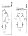
- FIG. 3 gives an example of an electrical configuration in the case of a heating device consisting of five concentric inductors.
- the two peripheral inductors 2 and 3 are connected so as to form a T with the central inductor 1.
- a third peripheral inductor 4 and a fourth peripheral inductor 5 are connected in shunt, and in series with the second peripheral inductor 3.
- a generator 10 is connected to a switch 11.
- the switch 11 makes it possible not to supply the inductors 2 and 3 simultaneously.
- four combinations of simultaneously powered inductors can be chosen according to the size.
- the central inductor 1 and the first peripheral inductor 2 these are: the central inductor 1 and the second peripheral inductor 3; the central inductor 1, the second peripheral inductor 3 and the third peripheral inductor 4; the central inductor 1, the second peripheral inductor 3 and the fourth peripheral inductor 5.
- the said combination is then kept throughout the heating step of the said charge.
- Figure 4 gives another example of electrical configuration in the case of a heater consisting of five concentric inductors.
- the two peripheral inductors 2 and 3 are connected so as to form a T with the central inductor 1.
- a third peripheral inductor 4 is connected in series with the first peripheral inductor 2.
- a fourth peripheral inductor 5 is connected in series with the second peripheral inductor 3.
- the peripheral inductors 4 and 5 can be short-circuited respectively with switches 12 and 13.
- generator 10 is connected to a switch 11.
- the switch 11 makes it possible not to supply the inductors 2 and 3 simultaneously.
- four combinations of simultaneously powered inductors can be chosen according to the size of the generator.
- the load is: the central inductor 1 and the first peripheral inductor 2; the central inductor 1 and the second peripheral inductor 3; the central inductor 1, the first peripheral inductor 2 and the third peripheral inductor 4; the central inductor 1, the second peripheral inductor 3 and the fourth peripheral inductor 5.
- the induction heating device preferably comprises a charge detection step.
- the charge detection step is performed by control means which also advantageously realize the charge heating step.
- the charge detection step consists in determining whether a load is located opposite one or more inductors, and in relation to which inductors said load is located.
- the charge detection step opposite the inductors comprises the successive supply of several sets of inductors, the measurement of the corresponding energies expended by the said power supply, the calculation of at least one difference between the measured energies, the determining the number of inductors covered by the detected load being made from the calculated difference (s).
- the measured energies can be directly compared with each other.
- the charge detection step advantageously comprises the following phases. Firstly, the inductors 1 and 2 are powered for a given time t during which the energy E (1 + 2) expended by the power supply is measured. Then, the inductors 1 and 3 are powered during the same given time t during which the energy E (1 + 3) expended by the power supply is measured. Then, the difference ⁇ between the measured energies E (1 + 2) and E (1 + 3) is calculated. If this difference ⁇ is greater than zero, that is to say if E (1 + 2)> E (1 + 3), then the inductors 1 and 2 are energized. If this difference ⁇ is less than zero, that is, if E (1 + 2) ⁇ E (1 + 3), then the inductors 1 and 3 are energized.
- the number of concentric inductors is preferably odd.
- the number of concentric inductors is advantageously equal to three; a heating device comprising three concentric inductors is commonly called "triple crown inductor".
- the induction heating device makes it possible to obtain good cooking results even with bad culinary containers, that is to say with culinary containers whose thermal conduction is not good enough to allow them to distribute very well. quickly possible localized hot spots.
- a more homogeneous distribution of the heat input to the load is particularly interesting in the case where the load, that is to say the cooking vessel, is large.
- the induction heating device according to the invention is particularly interesting for heating large stoves used for example for fried meat or fish.
- the outer diameter of the outermost peripheral inductor is substantially equal to that of a large frying pan.
Landscapes
- Physics & Mathematics (AREA)
- Electromagnetism (AREA)
- Cookers (AREA)
- General Induction Heating (AREA)
- Electric Stoves And Ranges (AREA)
Claims (14)
- Verfahren zur Erwärmung eines Kochgefäßes durch Induktion mit Hilfe einer Vorrichtung, die mindestens drei konzentrische Induktoren (1, 2, 3, 4, 5) aufweist, wobei das Verfahren einen Schritt zur Lasterwärmung umfasst, dadurch gekennzeichnet, dass für eine mindestens drei Induktoren bedeckende Last mindestens ein bedeckter Zwischeninduktor, der so bestimmt ist, dass die Zufuhr von Wärme zur Last homogenisiert ist, während des Erwärmungsschrittes nicht gespeist wird.
- Erwärmungsverfahren nach dem vorhergehenden Anspruch, dadurch gekennzeichnet, dass bei einer Last, die sowohl den mittleren Induktor (1) als auch mindestens zwei Umfangsinduktoren (2, 3, 4, 5) bedeckt, während des Erwärmungsschrittes unter den bedeckten Induktoren mehr gespeiste Induktoren als ungespeiste Induktoren vorhanden sind und weder drei aufeinanderfolgende gespeiste Induktoren noch zwei aufeinanderfolgende ungespeiste Induktoren vorhanden sind.
- Erwärmungsverfahren nach einem der vorhergehenden Ansprüche, dadurch gekennzeichnet, dass bei einer Last, die sowohl den mittleren Induktor (1) als auch mindestens zwei Umfangsinduktoren (2, 3, 4, 5) bedeckt, mindestens der mittlere Induktor (1) und der äußerste Umfangsinduktor zu den Induktoren gehören, die durch die Last bedeckt sind und gespeist werden.
- Erwärmungsverfahren nach einem der vorhergehenden Ansprüche, dadurch gekennzeichnet, dass es einen Schritt zur Erfassung der den Induktoren gegenüberliegenden Last umfasst.
- Erwärmungsverfahren nach Anspruch 4, dadurch gekennzeichnet, dass der Schritt zur Erfassung der den Induktoren gegenüberliegenden Last die sukzessive Speisung mehrerer Induktorsätze, die Messung der entsprechenden, durch die Speisung verbrauchten Energien (E(1+2), E(1+3)) und die Berechnung mindestens einer Differenz (Δ) zwischen den gemessenen Energien (E(1+2), E(1+3)) umfasst, wobei die Bestimmung der Anzahl der von der erfassten Last bedeckten Induktoren ausgehend von der berechneten Differenz (Δ) oder von den berechneten Differenzen (Δ) durchgeführt wird.
- Vorrichtung zur Erwärmung eines Kochgefäßes durch Induktion, mit mindestens drei konzentrischen Induktoren (1, 2, 3, 4, 5), wobei die Vorrichtung dazu geeignet ist, das Erwärmungsverfahren nach einem der Ansprüche 1 bis 5 anzuwenden.
- Erwärmungsvorrichtung nach Anspruch 6, dadurch gekennzeichnet, dass alle konzentrischen Induktoren (1 bis 5) mit ein und demselben Generator (10) verbunden sind.
- Erwärmungsvorrichtung nach Anspruch 6 oder 7, dadurch gekennzeichnet, dass der mittlere Induktor (1) mit der Baugruppe in Reihe geschaltet ist, die aus den beiden innersten Umfangsinduktoren (2 und 3) besteht, welche so geschaltet sind, dass sie mit dem mittleren Induktor (1) ein T bilden, und dass mindestens ein Schalter (11, 12, 13) so angeordnet ist, dass die beiden innersten Umfangsinduktoren (2 und 3) nicht gleichzeitig gespeist werden können.
- Erwärmungsvorrichtung nach Anspruch 8, dadurch gekennzeichnet, dass die Vorrichtung mindestens einen vierten konzentrischen Induktor (4) aufweist, der ausgehend von dem mittleren Induktor (1) der dritte Umfangsinduktor ist, mit dem zweiten Umfangsinduktor (3) in Reihe geschaltet ist und kurzgeschlossen werden kann.
- Erwärmungsvorrichtung nach Anspruch 9, dadurch gekennzeichnet, dass sich zwischen dem zweiten Umfangsinduktor (3) und dem dritten Umfangsinduktor (5) ein wesentlicher ringförmiger Raum (4) befindet.
- Erwärmungsvorrichtung nach Anspruch 9, dadurch gekennzeichnet, dass die Vorrichtung mindestens einen fünften konzentrischen Induktor (5) aufweist, der ausgehend von dem mittleren Induktor (1) der vierte Umfangsinduktor ist, zum dritten Umfangsinduktor (4) parallel geschaltet ist und kurzgeschlossen werden kann.
- Erwärmungsvorrichtung nach einem der Ansprüche 6 bis 11, dadurch gekennzeichnet, dass die Anzahl der konzentrischen Induktoren ungerade ist.
- Erwärmungsvorrichtung nach Anspruch 12, dadurch gekennzeichnet, dass die Anzahl der konzentrischen Induktoren drei beträgt.
- Erwärmungsvorrichtung nach einem der Ansprüche 6 bis 13, dadurch gekennzeichnet, dass der Außendurchmesser des äußersten Umfangsinduktors (3, 4, 5) im Wesentlichen dem einer großen Bratpfanne entspricht.
Applications Claiming Priority (2)
| Application Number | Priority Date | Filing Date | Title |
|---|---|---|---|
| FR0003601 | 2000-03-21 | ||
| FR0003601A FR2806868B1 (fr) | 2000-03-21 | 2000-03-21 | Dispositif de chauffage par induction de recipient culinaire |
Publications (2)
| Publication Number | Publication Date |
|---|---|
| EP1137324A1 EP1137324A1 (de) | 2001-09-26 |
| EP1137324B1 true EP1137324B1 (de) | 2006-08-09 |
Family
ID=8848338
Family Applications (1)
| Application Number | Title | Priority Date | Filing Date |
|---|---|---|---|
| EP01400717A Expired - Lifetime EP1137324B1 (de) | 2000-03-21 | 2001-03-20 | Induktive Heizvorrichtung für Kochbehälter |
Country Status (6)
| Country | Link |
|---|---|
| US (1) | US6633023B2 (de) |
| EP (1) | EP1137324B1 (de) |
| AT (1) | ATE336154T1 (de) |
| DE (1) | DE60122044T2 (de) |
| ES (1) | ES2267691T3 (de) |
| FR (1) | FR2806868B1 (de) |
Families Citing this family (26)
| Publication number | Priority date | Publication date | Assignee | Title |
|---|---|---|---|---|
| FR2863039B1 (fr) * | 2003-11-27 | 2006-02-17 | Brandt Ind | Procede de chauffage d'un recipient pose sur une table de cuisson a moyens de chauffage associe a des inducteurs |
| US7323666B2 (en) * | 2003-12-08 | 2008-01-29 | Saint-Gobain Performance Plastics Corporation | Inductively heatable components |
| ES2265758B1 (es) | 2005-03-01 | 2007-11-16 | Bsh Electrodomesticos España, S.A. | Dispositivo de calentamiento para una cocina de induccion. |
| FR2895639B1 (fr) * | 2005-12-27 | 2008-02-29 | Brandt Ind Sas | Foyer de cuisson par induction de taille variable |
| FR2902600B1 (fr) * | 2006-06-14 | 2008-09-05 | Brandt Ind Sas | Systeme a induction, procede d'alimentation d'un inducteur et table de cuisson comportant un tel systeme |
| ES2350174T3 (es) * | 2006-11-09 | 2011-01-19 | Menu-System Ag | Método para el control de un aparato de cocción por inducción y aparato de cocción por inducción. |
| JP5052329B2 (ja) * | 2007-12-27 | 2012-10-17 | 和光電研株式会社 | 電磁誘導加熱装置 |
| DE102008042512A1 (de) * | 2008-09-30 | 2010-04-01 | BSH Bosch und Siemens Hausgeräte GmbH | Kochfeld und Verfahren zum Betreiben eines Kochfelds |
| EP2209351B1 (de) * | 2009-01-16 | 2018-11-07 | Whirlpool Corporation | Verfahren zur Detektion der Brotgröße bei Induktionskochstellen und Induktionskochstelle zur Durchführung eines solchen Verfahrens |
| ES2356780B1 (es) * | 2009-01-20 | 2012-03-13 | Bsh Electrodomésticos España, S.A. | Campo de cocción con al menos una zona de calentamiento de varios elementos de calentamiento. |
| US9282593B2 (en) * | 2011-06-03 | 2016-03-08 | General Electric Company | Device and system for induction heating |
| ITTO20120896A1 (it) | 2012-10-15 | 2014-04-16 | Indesit Co Spa | Piano cottura a induzione |
| US10605464B2 (en) | 2012-10-15 | 2020-03-31 | Whirlpool Corporation | Induction cooktop |
| WO2014131721A1 (en) | 2013-02-26 | 2014-09-04 | Arcelik Anonim Sirketi | An induction cooktop and the control method thereof |
| US10591167B2 (en) * | 2015-10-28 | 2020-03-17 | Haier Us Appliance Solutions, Inc. | Cooktop appliance control system |
| EP3313145A1 (de) * | 2016-10-18 | 2018-04-25 | Electrolux Appliances Aktiebolag | Induktionskochfeld und verfahren zur überprüfung einer optimalen position eines kochtopfes auf dem induktionskochfeld |
| EP3432682B1 (de) | 2017-07-18 | 2026-04-08 | Whirlpool Corporation | Verfahren zum betreiben eines induktionskochfelds und kochfeld mit diesem verfahren |
| US10993292B2 (en) | 2017-10-23 | 2021-04-27 | Whirlpool Corporation | System and method for tuning an induction circuit |
| US12302478B2 (en) | 2018-04-23 | 2025-05-13 | Whirlpool Corporation | Control circuits and methods for distributed induction heating devices |
| US11140751B2 (en) | 2018-04-23 | 2021-10-05 | Whirlpool Corporation | System and method for controlling quasi-resonant induction heating devices |
| US12588112B2 (en) | 2018-04-23 | 2026-03-24 | Whirlpool Corporation | System and method for controlling induction heating devices with series connected switching devices |
| KR102933623B1 (ko) | 2019-12-18 | 2026-03-05 | 엘지전자 주식회사 | 고온 센싱이 가능한 유도 가열 방식의 쿡탑 |
| KR102933616B1 (ko) | 2019-12-18 | 2026-03-05 | 엘지전자 주식회사 | 박막의 열 변형을 줄인 유도 가열 방식의 쿡탑 |
| KR102849010B1 (ko) | 2020-02-13 | 2025-08-22 | 엘지전자 주식회사 | 다양한 물체를 가열하기 위한 유도 가열 방식의 쿡탑 |
| KR102880410B1 (ko) | 2020-04-02 | 2025-11-04 | 엘지전자 주식회사 | 복수의 부품의 온도에 기초한 출력 제어 알고리즘이 적용된 유도 가열 방식의 쿡탑 |
| KR102905443B1 (ko) * | 2021-02-03 | 2025-12-26 | 엘지전자 주식회사 | 유도 가열 장치 및 유도 가열 장치의 제어 방법 |
Family Cites Families (7)
| Publication number | Priority date | Publication date | Assignee | Title |
|---|---|---|---|---|
| FR2120564A5 (de) * | 1971-01-08 | 1972-08-18 | Stel | |
| US3843857A (en) * | 1972-05-26 | 1974-10-22 | R Cunningham | Induction heating system primarily intended for cooking use |
| GB1446737A (en) * | 1972-11-15 | 1976-08-18 | Matsushita Electric Industrial Co Ltd | Induction cooking appliances |
| EP0376760A1 (de) * | 1988-12-27 | 1990-07-04 | Bonnet S.A. | Induktiv geheizte Kochplatte |
| JPH03203187A (ja) * | 1989-12-28 | 1991-09-04 | Toshiba Corp | 誘導加熱調理器 |
| FR2672763B1 (fr) * | 1991-02-08 | 1993-05-07 | Bonnet Sa | Dispositif inducteur, destine au chauffage par induction de recipients pour la cuisine et procede de commande d'un tel dispositif. |
| FR2728132A1 (fr) * | 1994-12-09 | 1996-06-14 | Bonnet Sa | Dispositif de chauffage par induction de recipient et procede de commande d'un tel dispositif |
-
2000
- 2000-03-21 FR FR0003601A patent/FR2806868B1/fr not_active Expired - Fee Related
-
2001
- 2001-03-20 EP EP01400717A patent/EP1137324B1/de not_active Expired - Lifetime
- 2001-03-20 DE DE60122044T patent/DE60122044T2/de not_active Expired - Lifetime
- 2001-03-20 ES ES01400717T patent/ES2267691T3/es not_active Expired - Lifetime
- 2001-03-20 AT AT01400717T patent/ATE336154T1/de not_active IP Right Cessation
- 2001-03-21 US US09/813,136 patent/US6633023B2/en not_active Expired - Lifetime
Also Published As
| Publication number | Publication date |
|---|---|
| US20010025848A1 (en) | 2001-10-04 |
| FR2806868A1 (fr) | 2001-09-28 |
| ATE336154T1 (de) | 2006-09-15 |
| ES2267691T3 (es) | 2007-03-16 |
| EP1137324A1 (de) | 2001-09-26 |
| DE60122044T2 (de) | 2007-03-01 |
| FR2806868B1 (fr) | 2002-06-28 |
| US6633023B2 (en) | 2003-10-14 |
| DE60122044D1 (de) | 2006-09-21 |
Similar Documents
| Publication | Publication Date | Title |
|---|---|---|
| FR2806868A1 (fr) | Dispositif de chauffage par induction de recipient culinaire | |
| EP0716560B1 (de) | Induktionsheizvorrichtung für Behälter und Steuerungsverfahren dafür | |
| EP0971562B1 (de) | Mehrzweck-Induktionskochherd | |
| EP1967044B1 (de) | Induktionskochfeld mit variabeler grösse | |
| EP0757509B1 (de) | Vorrichtung zum induktiven Erwärmen von Speisegeschirr auf Tabletts | |
| EP0498735B1 (de) | Induktoranordnung zum Induktionsheizen von Kochgefässen und ihre Steuerungsanlage | |
| FR2792158A1 (fr) | Foyer de cuisson par induction modulable a rayonnement reduit et procede de realisation | |
| EP2039223A2 (de) | Kochfeld mit erfassung der temperatur eines küchenartikels | |
| EP0604617A1 (de) | Küchengeschirr mit wärmeleitendem boden. | |
| FR2766048A1 (fr) | Systeme d'echauffement | |
| EP2731474A1 (de) | Küchenartikel mit einer beheizten seitenwand und verfahren | |
| EP1967045B1 (de) | Induktorsvorrichtung versehen mit einzigen mehrwicklungen für induktiven kochfelden | |
| EP2454919B1 (de) | Vorrichtung zum induktiven erwärmen | |
| EP0376760A1 (de) | Induktiv geheizte Kochplatte | |
| FR2763201A1 (fr) | Dispositif de cuisson avec chauffage par induction et chauffage par resistance ainsi que le procede de fabrication de celui-ci | |
| EP2341757A1 (de) | Verfahren und Vorrichtung zur Bestimmung der minimalen induzierten Dauerleistung, insbesondere eines Induktionskochgeräts | |
| EP0929991B1 (de) | Kochmulde mit topfanwesenheitserkennung | |
| EP1824366B1 (de) | Tragbare nahrungsmittelerhitzungsvorrichtung | |
| FR2937407A1 (fr) | Accessoire pour table de cuisson formant interface avec un foyer de type wok | |
| EP3877700B1 (de) | Heizsystem und kochgerät mit demselben | |
| US20260114668A1 (en) | Electric Grill with Enhanced Conductive Heating | |
| EP2083608A1 (de) | Induktionskochgerät | |
| FR3067238B1 (fr) | Dispositif de chauffage d'un recipient de cuisson | |
| FR2665243A1 (fr) | Appareil de cuisson et de chauffe-plats. | |
| BE492017A (de) |
Legal Events
| Date | Code | Title | Description |
|---|---|---|---|
| PUAI | Public reference made under article 153(3) epc to a published international application that has entered the european phase |
Free format text: ORIGINAL CODE: 0009012 |
|
| AK | Designated contracting states |
Kind code of ref document: A1 Designated state(s): AT BE CH CY DE DK ES FI FR GB GR IE IT LI LU MC NL PT SE TR |
|
| AX | Request for extension of the european patent |
Free format text: AL;LT;LV;MK;RO;SI |
|
| 17P | Request for examination filed |
Effective date: 20020130 |
|
| AKX | Designation fees paid |
Free format text: AT BE CH CY DE DK ES FI FR GB GR IE IT LI LU MC NL PT SE TR |
|
| RAP1 | Party data changed (applicant data changed or rights of an application transferred) |
Owner name: BRANDT INDUSTRIES |
|
| GRAP | Despatch of communication of intention to grant a patent |
Free format text: ORIGINAL CODE: EPIDOSNIGR1 |
|
| GRAS | Grant fee paid |
Free format text: ORIGINAL CODE: EPIDOSNIGR3 |
|
| GRAA | (expected) grant |
Free format text: ORIGINAL CODE: 0009210 |
|
| AK | Designated contracting states |
Kind code of ref document: B1 Designated state(s): AT BE CH CY DE DK ES FI FR GB GR IE IT LI LU MC NL PT SE TR |
|
| PG25 | Lapsed in a contracting state [announced via postgrant information from national office to epo] |
Ref country code: IE Free format text: LAPSE BECAUSE OF FAILURE TO SUBMIT A TRANSLATION OF THE DESCRIPTION OR TO PAY THE FEE WITHIN THE PRESCRIBED TIME-LIMIT Effective date: 20060809 Ref country code: FI Free format text: LAPSE BECAUSE OF FAILURE TO SUBMIT A TRANSLATION OF THE DESCRIPTION OR TO PAY THE FEE WITHIN THE PRESCRIBED TIME-LIMIT Effective date: 20060809 Ref country code: IT Free format text: LAPSE BECAUSE OF FAILURE TO SUBMIT A TRANSLATION OF THE DESCRIPTION OR TO PAY THE FEE WITHIN THE PRESCRIBED TIME-LIMIT;WARNING: LAPSES OF ITALIAN PATENTS WITH EFFECTIVE DATE BEFORE 2007 MAY HAVE OCCURRED AT ANY TIME BEFORE 2007. THE CORRECT EFFECTIVE DATE MAY BE DIFFERENT FROM THE ONE RECORDED. Effective date: 20060809 Ref country code: AT Free format text: LAPSE BECAUSE OF FAILURE TO SUBMIT A TRANSLATION OF THE DESCRIPTION OR TO PAY THE FEE WITHIN THE PRESCRIBED TIME-LIMIT Effective date: 20060809 |
|
| REG | Reference to a national code |
Ref country code: GB Ref legal event code: FG4D Free format text: NOT ENGLISH |
|
| REG | Reference to a national code |
Ref country code: CH Ref legal event code: EP |
|
| REG | Reference to a national code |
Ref country code: IE Ref legal event code: FG4D Free format text: LANGUAGE OF EP DOCUMENT: FRENCH |
|
| REF | Corresponds to: |
Ref document number: 60122044 Country of ref document: DE Date of ref document: 20060921 Kind code of ref document: P |
|
| REG | Reference to a national code |
Ref country code: CH Ref legal event code: NV Representative=s name: KIRKER & CIE SA |
|
| PG25 | Lapsed in a contracting state [announced via postgrant information from national office to epo] |
Ref country code: SE Free format text: LAPSE BECAUSE OF FAILURE TO SUBMIT A TRANSLATION OF THE DESCRIPTION OR TO PAY THE FEE WITHIN THE PRESCRIBED TIME-LIMIT Effective date: 20061109 Ref country code: DK Free format text: LAPSE BECAUSE OF FAILURE TO SUBMIT A TRANSLATION OF THE DESCRIPTION OR TO PAY THE FEE WITHIN THE PRESCRIBED TIME-LIMIT Effective date: 20061109 |
|
| GBT | Gb: translation of ep patent filed (gb section 77(6)(a)/1977) |
Effective date: 20061024 |
|
| PG25 | Lapsed in a contracting state [announced via postgrant information from national office to epo] |
Ref country code: PT Free format text: LAPSE BECAUSE OF FAILURE TO SUBMIT A TRANSLATION OF THE DESCRIPTION OR TO PAY THE FEE WITHIN THE PRESCRIBED TIME-LIMIT Effective date: 20070109 |
|
| REG | Reference to a national code |
Ref country code: ES Ref legal event code: FG2A Ref document number: 2267691 Country of ref document: ES Kind code of ref document: T3 |
|
| REG | Reference to a national code |
Ref country code: IE Ref legal event code: FD4D |
|
| PLBE | No opposition filed within time limit |
Free format text: ORIGINAL CODE: 0009261 |
|
| STAA | Information on the status of an ep patent application or granted ep patent |
Free format text: STATUS: NO OPPOSITION FILED WITHIN TIME LIMIT |
|
| 26N | No opposition filed |
Effective date: 20070510 |
|
| PG25 | Lapsed in a contracting state [announced via postgrant information from national office to epo] |
Ref country code: MC Free format text: LAPSE BECAUSE OF NON-PAYMENT OF DUE FEES Effective date: 20070331 |
|
| PG25 | Lapsed in a contracting state [announced via postgrant information from national office to epo] |
Ref country code: GR Free format text: LAPSE BECAUSE OF FAILURE TO SUBMIT A TRANSLATION OF THE DESCRIPTION OR TO PAY THE FEE WITHIN THE PRESCRIBED TIME-LIMIT Effective date: 20061110 |
|
| PG25 | Lapsed in a contracting state [announced via postgrant information from national office to epo] |
Ref country code: CY Free format text: LAPSE BECAUSE OF FAILURE TO SUBMIT A TRANSLATION OF THE DESCRIPTION OR TO PAY THE FEE WITHIN THE PRESCRIBED TIME-LIMIT Effective date: 20060809 Ref country code: LU Free format text: LAPSE BECAUSE OF NON-PAYMENT OF DUE FEES Effective date: 20070320 |
|
| PG25 | Lapsed in a contracting state [announced via postgrant information from national office to epo] |
Ref country code: TR Free format text: LAPSE BECAUSE OF FAILURE TO SUBMIT A TRANSLATION OF THE DESCRIPTION OR TO PAY THE FEE WITHIN THE PRESCRIBED TIME-LIMIT Effective date: 20060809 |
|
| PGFP | Annual fee paid to national office [announced via postgrant information from national office to epo] |
Ref country code: BE Payment date: 20100519 Year of fee payment: 10 Ref country code: CH Payment date: 20100413 Year of fee payment: 10 |
|
| PGFP | Annual fee paid to national office [announced via postgrant information from national office to epo] |
Ref country code: NL Payment date: 20110331 Year of fee payment: 11 |
|
| PGFP | Annual fee paid to national office [announced via postgrant information from national office to epo] |
Ref country code: GB Payment date: 20110404 Year of fee payment: 11 |
|
| BERE | Be: lapsed |
Owner name: *BRANDT INDUSTRIES Effective date: 20110331 |
|
| REG | Reference to a national code |
Ref country code: FR Ref legal event code: CD Owner name: FAGORBRANDT SAS, FR Effective date: 20110826 |
|
| REG | Reference to a national code |
Ref country code: CH Ref legal event code: PL |
|
| REG | Reference to a national code |
Ref country code: ES Ref legal event code: PC2A Owner name: FAGORBRANDT SAS Effective date: 20111021 |
|
| REG | Reference to a national code |
Ref country code: NL Ref legal event code: TD Effective date: 20111221 |
|
| PG25 | Lapsed in a contracting state [announced via postgrant information from national office to epo] |
Ref country code: BE Free format text: LAPSE BECAUSE OF NON-PAYMENT OF DUE FEES Effective date: 20110331 |
|
| PG25 | Lapsed in a contracting state [announced via postgrant information from national office to epo] |
Ref country code: CH Free format text: LAPSE BECAUSE OF NON-PAYMENT OF DUE FEES Effective date: 20110331 Ref country code: LI Free format text: LAPSE BECAUSE OF NON-PAYMENT OF DUE FEES Effective date: 20110331 |
|
| REG | Reference to a national code |
Ref country code: DE Ref legal event code: R082 Ref document number: 60122044 Country of ref document: DE Representative=s name: PRINZ & PARTNER PATENTANWAELTE RECHTSANWAELTE, DE Effective date: 20120322 Ref country code: DE Ref legal event code: R081 Ref document number: 60122044 Country of ref document: DE Owner name: FAGORBRANDT SAS, FR Free format text: FORMER OWNER: BRANDT INDUSTRIES, RUEIL MALMAISON, FR Effective date: 20120322 Ref country code: DE Ref legal event code: R082 Ref document number: 60122044 Country of ref document: DE Representative=s name: PRINZ & PARTNER MBB PATENTANWAELTE RECHTSANWAE, DE Effective date: 20120322 Ref country code: DE Ref legal event code: R081 Ref document number: 60122044 Country of ref document: DE Owner name: GROUPE BRANDT, FR Free format text: FORMER OWNER: BRANDT INDUSTRIES, RUEIL MALMAISON, FR Effective date: 20120322 |
|
| REG | Reference to a national code |
Ref country code: NL Ref legal event code: V1 Effective date: 20121001 |
|
| GBPC | Gb: european patent ceased through non-payment of renewal fee |
Effective date: 20120320 |
|
| PG25 | Lapsed in a contracting state [announced via postgrant information from national office to epo] |
Ref country code: GB Free format text: LAPSE BECAUSE OF NON-PAYMENT OF DUE FEES Effective date: 20120320 |
|
| PG25 | Lapsed in a contracting state [announced via postgrant information from national office to epo] |
Ref country code: NL Free format text: LAPSE BECAUSE OF NON-PAYMENT OF DUE FEES Effective date: 20121001 |
|
| REG | Reference to a national code |
Ref country code: ES Ref legal event code: PC2A Owner name: GROUPE BRANDT Effective date: 20160226 |
|
| REG | Reference to a national code |
Ref country code: DE Ref legal event code: R082 Ref document number: 60122044 Country of ref document: DE Representative=s name: PRINZ & PARTNER MBB PATENTANWAELTE RECHTSANWAE, DE Ref country code: FR Ref legal event code: PLFP Year of fee payment: 16 Ref country code: DE Ref legal event code: R081 Ref document number: 60122044 Country of ref document: DE Owner name: GROUPE BRANDT, FR Free format text: FORMER OWNER: FAGORBRANDT SAS, RUEIL-MALMAISON, FR |
|
| REG | Reference to a national code |
Ref country code: FR Ref legal event code: TP Owner name: GROUPE BRANDT, FR Effective date: 20160420 |
|
| REG | Reference to a national code |
Ref country code: FR Ref legal event code: GC Effective date: 20160426 |
|
| REG | Reference to a national code |
Ref country code: FR Ref legal event code: PLFP Year of fee payment: 17 |
|
| REG | Reference to a national code |
Ref country code: FR Ref legal event code: PLFP Year of fee payment: 18 |
|
| PGFP | Annual fee paid to national office [announced via postgrant information from national office to epo] |
Ref country code: ES Payment date: 20180405 Year of fee payment: 18 |
|
| PGFP | Annual fee paid to national office [announced via postgrant information from national office to epo] |
Ref country code: DE Payment date: 20180710 Year of fee payment: 18 Ref country code: IT Payment date: 20180712 Year of fee payment: 18 |
|
| PGFP | Annual fee paid to national office [announced via postgrant information from national office to epo] |
Ref country code: FR Payment date: 20190314 Year of fee payment: 19 |
|
| REG | Reference to a national code |
Ref country code: DE Ref legal event code: R119 Ref document number: 60122044 Country of ref document: DE |
|
| PG25 | Lapsed in a contracting state [announced via postgrant information from national office to epo] |
Ref country code: DE Free format text: LAPSE BECAUSE OF NON-PAYMENT OF DUE FEES Effective date: 20191001 |
|
| PG25 | Lapsed in a contracting state [announced via postgrant information from national office to epo] |
Ref country code: IT Free format text: LAPSE BECAUSE OF NON-PAYMENT OF DUE FEES Effective date: 20190320 |
|
| REG | Reference to a national code |
Ref country code: ES Ref legal event code: FD2A Effective date: 20200727 |
|
| PG25 | Lapsed in a contracting state [announced via postgrant information from national office to epo] |
Ref country code: ES Free format text: LAPSE BECAUSE OF NON-PAYMENT OF DUE FEES Effective date: 20190321 |
|
| PG25 | Lapsed in a contracting state [announced via postgrant information from national office to epo] |
Ref country code: FR Free format text: LAPSE BECAUSE OF NON-PAYMENT OF DUE FEES Effective date: 20200331 |