EP2083608A1 - Induktionskochgerät - Google Patents
Induktionskochgerät Download PDFInfo
- Publication number
- EP2083608A1 EP2083608A1 EP09300002A EP09300002A EP2083608A1 EP 2083608 A1 EP2083608 A1 EP 2083608A1 EP 09300002 A EP09300002 A EP 09300002A EP 09300002 A EP09300002 A EP 09300002A EP 2083608 A1 EP2083608 A1 EP 2083608A1
- Authority
- EP
- European Patent Office
- Prior art keywords
- screen
- cooking appliance
- appliance according
- induction cooking
- inductor
- Prior art date
- Legal status (The legal status is an assumption and is not a legal conclusion. Google has not performed a legal analysis and makes no representation as to the accuracy of the status listed.)
- Withdrawn
Links
- 230000006698 induction Effects 0.000 title claims description 20
- 238000010411 cooking Methods 0.000 claims abstract description 60
- XAGFODPZIPBFFR-UHFFFAOYSA-N aluminium Chemical compound [Al] XAGFODPZIPBFFR-UHFFFAOYSA-N 0.000 claims abstract description 7
- 229910052782 aluminium Inorganic materials 0.000 claims abstract description 7
- 210000001520 comb Anatomy 0.000 claims description 15
- 238000009413 insulation Methods 0.000 claims description 9
- OKTJSMMVPCPJKN-UHFFFAOYSA-N Carbon Chemical compound [C] OKTJSMMVPCPJKN-UHFFFAOYSA-N 0.000 claims description 7
- 229910052799 carbon Inorganic materials 0.000 claims description 7
- 229910000859 α-Fe Inorganic materials 0.000 claims description 7
- 238000010292 electrical insulation Methods 0.000 claims description 5
- 239000010445 mica Substances 0.000 claims description 3
- 229910052618 mica group Inorganic materials 0.000 claims description 3
- 239000000123 paper Substances 0.000 claims description 3
- 229920001296 polysiloxane Polymers 0.000 claims description 3
- 238000007650 screen-printing Methods 0.000 claims description 3
- 239000003990 capacitor Substances 0.000 description 11
- 239000012212 insulator Substances 0.000 description 6
- 239000000615 nonconductor Substances 0.000 description 5
- 239000004020 conductor Substances 0.000 description 3
- 230000000694 effects Effects 0.000 description 3
- 238000010438 heat treatment Methods 0.000 description 3
- 238000010276 construction Methods 0.000 description 2
- 239000003973 paint Substances 0.000 description 2
- 230000003071 parasitic effect Effects 0.000 description 2
- 230000006978 adaptation Effects 0.000 description 1
- 230000008878 coupling Effects 0.000 description 1
- 238000010168 coupling process Methods 0.000 description 1
- 238000005859 coupling reaction Methods 0.000 description 1
- 230000009977 dual effect Effects 0.000 description 1
- 230000005670 electromagnetic radiation Effects 0.000 description 1
- 239000011521 glass Substances 0.000 description 1
- 239000002241 glass-ceramic Substances 0.000 description 1
- 239000007788 liquid Substances 0.000 description 1
- 238000004519 manufacturing process Methods 0.000 description 1
- 229920001721 polyimide Polymers 0.000 description 1
- 238000004804 winding Methods 0.000 description 1
Images


Classifications
-
- H—ELECTRICITY
- H05—ELECTRIC TECHNIQUES NOT OTHERWISE PROVIDED FOR
- H05B—ELECTRIC HEATING; ELECTRIC LIGHT SOURCES NOT OTHERWISE PROVIDED FOR; CIRCUIT ARRANGEMENTS FOR ELECTRIC LIGHT SOURCES, IN GENERAL
- H05B6/00—Heating by electric, magnetic or electromagnetic fields
- H05B6/02—Induction heating
- H05B6/10—Induction heating apparatus, other than furnaces, for specific applications
- H05B6/12—Cooking devices
- H05B6/1209—Cooking devices induction cooking plates or the like and devices to be used in combination with them
- H05B6/1245—Cooking devices induction cooking plates or the like and devices to be used in combination with them with special coil arrangements
- H05B6/1272—Cooking devices induction cooking plates or the like and devices to be used in combination with them with special coil arrangements with more than one coil or coil segment per heating zone
-
- Y—GENERAL TAGGING OF NEW TECHNOLOGICAL DEVELOPMENTS; GENERAL TAGGING OF CROSS-SECTIONAL TECHNOLOGIES SPANNING OVER SEVERAL SECTIONS OF THE IPC; TECHNICAL SUBJECTS COVERED BY FORMER USPC CROSS-REFERENCE ART COLLECTIONS [XRACs] AND DIGESTS
- Y02—TECHNOLOGIES OR APPLICATIONS FOR MITIGATION OR ADAPTATION AGAINST CLIMATE CHANGE
- Y02B—CLIMATE CHANGE MITIGATION TECHNOLOGIES RELATED TO BUILDINGS, e.g. HOUSING, HOUSE APPLIANCES OR RELATED END-USER APPLICATIONS
- Y02B40/00—Technologies aiming at improving the efficiency of home appliances, e.g. induction cooking or efficient technologies for refrigerators, freezers or dish washers
Definitions
- the present invention relates to an induction cooking appliance with at least one hearth according to the preamble of claim 1.
- Induction cooking appliances also called cooking plates of the type defined above, comprises one or more focus (s) that is to say one or more locations for receiving a cooking utensil such as a container, pan or other whose bottom and walls will be heated by the current induced by the inductor.
- Cookware has magnetic characteristics to allow this coupling.
- Another solution proposed is to surround the inductor with a non-magnetic shield in the form of a cage to reflect the disturbances and try to contain them.
- Another proposed solution consists in superimposing two inductors with currents flowing in opposite directions.
- the inductor of an induction furnace located near the utensil to be heated has a surface facing the pan. This large area is proportional to the area facing the inductor and the pan.
- the capacitor thus formed has a capacitance a few dozen picofarads (pF).
- This capacitor is charged by the AC voltage involved between the inductor and the pan, the latter being electrically insulated by the plate forming the cooking surface.
- the pan constituting the second plate of the capacitor is thus charged to a voltage that can reach several tens of volts.
- This tension is felt when you touch the pan, in the form of a small discharge. Although this discharge is not in itself dangerous, it is nevertheless troublesome and disruptive. An informed person will not be surprised by this discharge, but an uninformed person may be and make a sudden gesture that can become dangerous because the utensil such as the pan may contain heated products for example a liquid which can be knocked over or hurt by burning.
- the magnetic shield is formed by a loop, the crown effect is emphasized, ie the maximum heating line because the magnetic field lines converge towards the maximum heating zone which is concentric to a circular inductor.
- the object of the present invention is to develop an induction cooking appliance making it possible to greatly reduce or even eliminate the parasitic voltage of a cooking utensil placed on the cooking surface of an induction cooking appliance without impairing the performance of the cooking appliance. home or create a strongly heated element nor further increase the crown effect, and this with simple and economical means, integrated into the cooking appliance.
- the present invention relates to an induction cooking appliance of the type defined above characterized by the features of the first claim.
- the electric screen that is to say electrically conductive but not magnetic can transfer the electric power of the inductor to the kitchen utensil placed on the cooking surface while avoiding that the cooking utensil constitutes a capacitor with the inductor.
- This capacitor is replaced by the one formed by the screen placed above the inductor and in all cases in the interval between the inductor and the cooking utensil.
- This capacitor is primarily responsible for the capacitor which is formed by the screen and the cooking utensil and thanks to its digitized structure without forming a loop, considerably reduces the corona effect and therefore the power lost.
- the capacitor formed by the utensil and the screen can not be charged since the screen is connected to the electrical ground of the cooking appliance which is generally the frame of the appliance.
- the electric screen according to the invention which has a digitized structure, that is to say a set of fingers or branches of which one end is free and the other is connected to a common part itself connected to the mass , is carried out particularly interestingly in a comb form, that is to say a back bearing teeth including parallel but not constituting in any case a loop.
- the teeth and the back of the comb which are constituted by parallel ribbons, regularly cover the surface of the inductor in the manner of a grid without creating loops in which could circulate an electric current.
- This structure of the electroconductive screen is easy to achieve, especially if it is aluminum, which has the advantage of being good conductor, non-magnetic and lightweight which further reduces heating.
- the electric screen is formed of two combs paired by their backs, parallel, and one end of which is connected to a common tab, grounded, the teeth of the combs being directed in opposite directions.
- This electroconductive screen formed by two paired combs thus assembled, to the advantage of being able to be fixed to the mass by the two combs each separately connected to the mass, while ensuring a good coverage of the surface of the armature while remaining very permeable to the electromagnetic radiation of the inductor.
- the electric screen is formed of two paired combs whose ends of the teeth are turned towards each other, without contact and the back of each comb comprises a tab separately connected to ground.
- This other embodiment of a double twin comb screen is particularly suitable for a cooking appliance whose cooking point consists of four combined inductors and, in particular, square inductors, facilitating the modular construction of the cooking appliances.
- This embodiment with four inductors is also possible with twin combs, whose teeth are opposite.
- the electrical screen is formed of a bonded subassembly, composed of the digitized structure applied to a thermal insulation and covered with an electrical insulator.
- This glued subassembly constitutes a part of a cooking appliance in the same way as the inductor and the other elements, allowing a separate manufacture for assembling the cooking appliance.
- This subassembly is also advantageous for a modular construction of the cooking appliance, for its adaptation to different sizes and different powers.
- the bonded subassembly as defined above is characterized in that the thermal insulator is a refractory cardboard, in particular a laminate of paper and mica, impregnated with silicone having a thermal resistance up to 700 ° C. and good cutability.
- the thermal insulator is a refractory cardboard, in particular a laminate of paper and mica, impregnated with silicone having a thermal resistance up to 700 ° C. and good cutability.
- the electric screen is made of aluminum with a thickness of 150 microns or carbon or an electroconductive but non-magnetic paint.
- the aluminum screen can preferably be fixed under the plate forming the cooking surface. It can also be integrated in the mass of the plate or be fixed on the top of the plate while being embedded in the upper surface.
- a carbon screen it is preferably made by screen printing on a support and in particular the underside of the cooking plate or on or in its upper surface.
- the carbon screen is connected, like the aluminum screen, or other electrically conductive material but not magnetic, by an electrical connection to the electrical ground of the cooking appliance.
- the cooking apparatus according to the invention is carried out under very simple and economical conditions, comparable to a cooking apparatus which does not include such an electric screen.
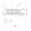
- the figure 1 shows schematically and partially an induction cooking appliance.
- the representation is limited to a focus 100 of this device which may include several, especially in modular form.
- the cooking apparatus 100 is composed of a frame 110 carrying a plate 120 forming the cooking surface on which a utensil 200 is placed, for example a saucepan.
- the hearth 100 is formed of an inductor 101 placed under the plate 120 and separated therefrom by a set composed of an electric screen having a digitized structure 102 whose fingers or branches have one free end and the other, connected to a common part itself connected to the mass.
- the structure or screen 102 is above a thermal insulation layer 103 and surmounted by an electrical insulation layer 104.
- the electric screen 102 and the two layers 103, 104 preferably constitute a sub-layer. assembled by collage.
- the electric screen 102 is connected to the chassis 110 by an electrical connection 105, the chassis constituting the mass.
- the inductor 101 is placed with the interposition of an electrical insulator 106 over ferrites 107 and the assembly is carried by a printed circuit 109 providing electrical power to the inductor 101 separated from the ferrites 107 by an electrical insulator 108
- the generator 130 supplying the printed circuit is represented by a rectangle.
- the inductor 101 shown schematically can be composed of several parts whose power supply by the generator 130 is controlled according to the power required according to the dimensions of the cookware placed above or the load to be heated.
- control means 140 acting on the generator 130 and the operating program of the cooking appliance. These known means are not shown here in detail.
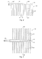
- the electrical screen 100 electrically conductive, non-magnetic is constituted by a planar aluminum planar structure, in the form of a grid or, more accurately, a comb 300 comprising a back 301 bearing teeth 302, one end 302A of which is connected to the back 301; the other end 302B being free.
- These teeth 302 and the back 301 are formed by ribbons, parallel to the teeth, and regularly covering a certain surface.
- the back 301 is connected to a tab 303 for connection to the chassis 110 for connection to ground.
- the teeth 302 are preferably of the same length except one of the teeth 304, leaving an unobstructed portion ZD to constitute a point of attachment of the subset of the electric screen.
- the corners 304, 305 of the screen, at both ends of the back 301 and branches are truncated to fit the particular shape of the fireplace.
- the comb 300 is with its teeth a set of conductive branches 302 forming a capacitor plate. But these branches are not looped so that there can be a circulation of electric current loop.
- the figure 3 discloses another embodiment of an electrically non-magnetic electrically conductive screen 400, which can be considered as constituted by the schematic assembly of two comb shapes such as that of the figure 2 , back to back.
- the screen 400 consists of two main branches 401, 402 parallel and apart and bearing teeth or branches 403, 404 directed in opposite directions, and parallel to each other.
- the backs or main branches 401, 402 are connected to a common tab 405 for the connection to ground.
- the paired comb form shown in figure 3 is a symmetrical form although other forms, not symmetrical, can be envisaged.
- This form of paired combs or, more simply, of comb 400 does not constitute a closed loop in which the current could circulate since all the teeth 403, 404 end with a free end 403B, 404B and the two backs 401, 402 are united at one end and not at both ends.
- the branches 401, 402, 403, 404 of the backs and teeth are formed of parallel ribbons, preferably of identical thickness.
- the figure 4 shows in section, the realization of a subset forming an electric screen 500 comprising a comb 510 as the combs 300, 400 presented to Figures 2, 3 , provided with a thermal insulation 520 on its underside and an electrical insulator 530 on the other side; the comb 510 is sandwiched between these two insulators 520, 530; the assembly is assembled, in particular glued. Exceeds from this assembly only the end of the branching lugs 303 of the two combs 300 ( figure 5 ) or the single leg 405 of the comb 40 ( figure 6 ).
- the electrical insulation 530 is, for example, a polyimide film such as those used for insulating electrical conductors, and resistant to a certain temperature.
- the thermal insulation 520 which constitutes the underside of the above subassembly, (depending on the orientation of the figure 1 ) is preferably a refractory cardboard and in particular a laminate of paper and mica, impregnated with silicone. Such a cardboard can have a good thermal resistance up to 700 ° and it is easily cut.
- the figure 5 shows a screen subassembly form 600 composed of two paired combs 300 according to the figure 2 , whose teeth 302 are facing each other and the figure 6 , a screen subset 700 formed of a comb 400 of the figure 3 .
- the electric screen has a generally square surface with truncated corners.
- truncated corners 304, 305 are part of the comb structure.
- the vertices of the square of the screen are truncated by necessity to be installed in a home as below.
- the subset 600 of the screen of the figure 5 consists of two insulators 520, 530 of generally square contour with truncated corners, surrounding the contour of two combs 300 ( figure 2 ) arranged symmetrically one facing each other so that the ends 302B of the teeth 302 are facing but not touching.
- the teeth 304 leave empty the ZD location provided with a fixing orifice 601.
- the two combs 300 are sandwiched between the two insulators 320, 330 and only the branching tabs 303 protrude to be connected to ground.
- the subset 700 of the screen of the figure 6 consists of the comb 400 of the figure 3 , sandwiched between two insulators 520, 530 of square shape, with truncated corners, corresponding to the contour of the hearth as the figure 5 .
- the only leg 405 protrudes from the subassembly 700.
- FIGS. 5 and 6 show that the backs 301, the teeth 302, the branches 401, 402, the teeth 430, 404 occupy the hearth surface by a regular distribution without creating a current loop.
- the figure 7 is a plan view of a fireplace 100A formed of four inductors 101A, B, C, D, covered by a screen 600 such as that of the figure 5 whose Figure 7A shows a schematic section.
- the description of this cup uses the same references as the figure 1 to designate the same elements whose description will not be repeated.
- the figure 8 shows another form of hearth 100B, also composed of four inductors 101A, B, C, D but covered by a screen 700 like that of the figure 6 .
- the four square inductors 101A, B, C, D represent a maximum total power of 4 KW.
- These square inductors are placed on ferrites of corresponding shape, being separated therefrom by an electrical insulator. The ferrites are themselves above the printed circuit board, with the interposition of another insulator.
- the inductors 101A, B, C, D have a substantially square truncated peak shape coil that the shape of the electric screen 600, 700 marries and covers globally.
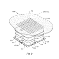
- the figure 9 is an exploded view of a cooking apparatus 100B according to the figure 8 .
- This cooking appliance consists of a printed circuit 109 for the supply of the inductors 101A, B, C, D. Above of the printed circuit, there is an electrical insulation layer 108 surmounted by the ferrites 107A, B, C, D, themselves surmounted by the inductors 101A, B, C, D with the interposition of an electrical insulation layer 106. It is the same inductors that are separated from the electric screen, not detailed here, by an insulation layer 103.
- the screen is represented by its comb 400 appearing under the transparent cooking plate 120 which is a transparent or translucent plate, for example a glass plate or glass-ceramic.
- the comb 400 of the electric screen appears through the plate 120 and above the thermal insulation 103, the inductors 101A, B, C, D and the ferrites 107A, B, C, D and the plate of circuit 109.
- the figure 10 shows another embodiment of the cooking apparatus 100C in which the electric screen is on the surface of the cooking plate.
- This screen is limited to a comb 40C is embedded in the hob 120C, integrated in the thickness thereof or embedded in it on the surface. It is preferably an inlaid carbon screen then ensuring a dual function since it constitutes both the second plate of the capacitor that it forms with the inductor and on the other hand being connected to ground, in connecting to the mass, the kitchen utensil placed above him.
- the carbon screen is printed on the underside of the plate 120C or on the upper face thereof. It can be a carbon paint, applied by screen printing.
- the screen must withstand the relatively high temperatures to which it can be subjected because of its proximity to the cookware that will be heated.
Landscapes
- Physics & Mathematics (AREA)
- Electromagnetism (AREA)
- Cookers (AREA)
Applications Claiming Priority (1)
| Application Number | Priority Date | Filing Date | Title |
|---|---|---|---|
| FR0850496A FR2926946B1 (fr) | 2008-01-28 | 2008-01-28 | Appareil de cuisson par induction. |
Publications (1)
| Publication Number | Publication Date |
|---|---|
| EP2083608A1 true EP2083608A1 (de) | 2009-07-29 |
Family
ID=39691211
Family Applications (1)
| Application Number | Title | Priority Date | Filing Date |
|---|---|---|---|
| EP09300002A Withdrawn EP2083608A1 (de) | 2008-01-28 | 2009-01-21 | Induktionskochgerät |
Country Status (2)
| Country | Link |
|---|---|
| EP (1) | EP2083608A1 (de) |
| FR (1) | FR2926946B1 (de) |
Cited By (1)
| Publication number | Priority date | Publication date | Assignee | Title |
|---|---|---|---|---|
| DE102010027880A1 (de) * | 2010-04-16 | 2011-10-20 | E.G.O. Elektro-Gerätebau GmbH | Vorrichtung zum Abschirmen eines elektrischen Störfelds einer Induktionsheizspule und Induktionsheizeinrichtung |
Citations (6)
| Publication number | Priority date | Publication date | Assignee | Title |
|---|---|---|---|---|
| US2047159A (en) * | 1935-07-17 | 1936-07-07 | Galvin Mfg Corp | Electrostatic shield |
| US4163139A (en) * | 1972-09-18 | 1979-07-31 | White Consolidated Industries, Inc. | Cooking vessel capacitive decoupling for induction cooking apparatus |
| US5428207A (en) * | 1992-03-14 | 1995-06-27 | E.G.O. Elecktro-Gerate Blanc U. Fischer | Inductive based cooking system |
| EP0706304A1 (de) * | 1994-10-09 | 1996-04-10 | Menu-System Ernst Wüst | Kochgerät |
| US6956688B2 (en) | 2001-02-20 | 2005-10-18 | Advantest Corporation | Variable width optical slit mechanism |
| DE202004021071U1 (de) * | 2004-11-09 | 2006-08-24 | Schott Ag | Induktiv beheiztes Kochfeld |
-
2008
- 2008-01-28 FR FR0850496A patent/FR2926946B1/fr not_active Expired - Fee Related
-
2009
- 2009-01-21 EP EP09300002A patent/EP2083608A1/de not_active Withdrawn
Patent Citations (6)
| Publication number | Priority date | Publication date | Assignee | Title |
|---|---|---|---|---|
| US2047159A (en) * | 1935-07-17 | 1936-07-07 | Galvin Mfg Corp | Electrostatic shield |
| US4163139A (en) * | 1972-09-18 | 1979-07-31 | White Consolidated Industries, Inc. | Cooking vessel capacitive decoupling for induction cooking apparatus |
| US5428207A (en) * | 1992-03-14 | 1995-06-27 | E.G.O. Elecktro-Gerate Blanc U. Fischer | Inductive based cooking system |
| EP0706304A1 (de) * | 1994-10-09 | 1996-04-10 | Menu-System Ernst Wüst | Kochgerät |
| US6956688B2 (en) | 2001-02-20 | 2005-10-18 | Advantest Corporation | Variable width optical slit mechanism |
| DE202004021071U1 (de) * | 2004-11-09 | 2006-08-24 | Schott Ag | Induktiv beheiztes Kochfeld |
Cited By (1)
| Publication number | Priority date | Publication date | Assignee | Title |
|---|---|---|---|---|
| DE102010027880A1 (de) * | 2010-04-16 | 2011-10-20 | E.G.O. Elektro-Gerätebau GmbH | Vorrichtung zum Abschirmen eines elektrischen Störfelds einer Induktionsheizspule und Induktionsheizeinrichtung |
Also Published As
| Publication number | Publication date |
|---|---|
| FR2926946B1 (fr) | 2016-04-08 |
| FR2926946A1 (fr) | 2009-07-31 |
Similar Documents
| Publication | Publication Date | Title |
|---|---|---|
| EP0713351B1 (de) | Induktions-Kochmulde | |
| BE1013307A3 (fr) | Foyer de cuisson par induction modulable a rayonnement reduit et procede de realisation. | |
| EP0277075B1 (de) | Induktive Heizung für elektrische Kochplatte | |
| EP1575336B1 (de) | Zusammensetzungsmodul von Induktionsspulen einer Induktionskochzone und Kochzone ausgestattet mit solchem Modul | |
| CH640681A5 (fr) | Ensemble electrique chauffant a rayonnement. | |
| EP1137324B1 (de) | Induktive Heizvorrichtung für Kochbehälter | |
| FR2748885A1 (fr) | Foyer de cuisson par induction a rendement eleve | |
| EP2039223A2 (de) | Kochfeld mit erfassung der temperatur eines küchenartikels | |
| EP3041391A1 (de) | Schüssel eines garbehälters mit einer halterung versehen mit einer elektrischen vorrichtung | |
| FR2805143A1 (fr) | Grille-pain a parois chauffantes transparentes | |
| EP2445309A1 (de) | Temperaturmessvorrichtung für eine Gruppe von Induktoren eines Induktionskochfeldes, und zugehöriges Induktionskochfeld | |
| FR3012008A1 (fr) | Element chauffant a couche epaisse et equipement de cuisine comportant un tel element chauffant | |
| EP2454919B1 (de) | Vorrichtung zum induktiven erwärmen | |
| EP0713349A1 (de) | Induktionskochgerät mit reduziertem Störstrahlung | |
| WO2007074243A2 (fr) | Dispositif inducteur a bobinages individuels multiples pour foyer de cuisson par induction | |
| EP2490505A1 (de) | Induktionskochherd, und entsprechendes Induktionskochfeld | |
| EP2083608A1 (de) | Induktionskochgerät | |
| EP0376760A1 (de) | Induktiv geheizte Kochplatte | |
| FR2763201A1 (fr) | Dispositif de cuisson avec chauffage par induction et chauffage par resistance ainsi que le procede de fabrication de celui-ci | |
| EP0929991B1 (de) | Kochmulde mit topfanwesenheitserkennung | |
| FR3005388A1 (fr) | Element de chauffage a sections ayant differentes puissances de chauffage, et appareil de cuisson. | |
| EP0771135B1 (de) | Aus Litzenleitern induktive Wicklung eines Induktionskochgerätes | |
| JP2010262751A (ja) | 複合誘導加熱調理器 | |
| JP5810281B2 (ja) | グリル調理容器 | |
| EP2226568A2 (de) | Kochfeld Zubehör, das ein Interface mit einem Wok-Typ Kochplatte bildet |
Legal Events
| Date | Code | Title | Description |
|---|---|---|---|
| PUAI | Public reference made under article 153(3) epc to a published international application that has entered the european phase |
Free format text: ORIGINAL CODE: 0009012 |
|
| AK | Designated contracting states |
Kind code of ref document: A1 Designated state(s): AT BE BG CH CY CZ DE DK EE ES FI FR GB GR HR HU IE IS IT LI LT LU LV MC MK MT NL NO PL PT RO SE SI SK TR |
|
| AX | Request for extension of the european patent |
Extension state: AL BA RS |
|
| AKX | Designation fees paid | ||
| REG | Reference to a national code |
Ref country code: DE Ref legal event code: 8566 |
|
| STAA | Information on the status of an ep patent application or granted ep patent |
Free format text: STATUS: THE APPLICATION IS DEEMED TO BE WITHDRAWN |
|
| 18D | Application deemed to be withdrawn |
Effective date: 20100130 |