EP1138340A2 - Dispositif pour l'évacuation de gaz respiratoire - Google Patents
Dispositif pour l'évacuation de gaz respiratoire Download PDFInfo
- Publication number
- EP1138340A2 EP1138340A2 EP01105435A EP01105435A EP1138340A2 EP 1138340 A2 EP1138340 A2 EP 1138340A2 EP 01105435 A EP01105435 A EP 01105435A EP 01105435 A EP01105435 A EP 01105435A EP 1138340 A2 EP1138340 A2 EP 1138340A2
- Authority
- EP
- European Patent Office
- Prior art keywords
- connection section
- breathing gas
- channels
- connection
- here
- Prior art date
- Legal status (The legal status is an assumption and is not a legal conclusion. Google has not performed a legal analysis and makes no representation as to the accuracy of the status listed.)
- Granted
Links
- 230000000241 respiratory effect Effects 0.000 title description 2
- 230000029058 respiratory gaseous exchange Effects 0.000 claims abstract description 47
- 239000000463 material Substances 0.000 claims description 16
- 230000008878 coupling Effects 0.000 claims description 7
- 238000010168 coupling process Methods 0.000 claims description 7
- 238000005859 coupling reaction Methods 0.000 claims description 7
- 229920002379 silicone rubber Polymers 0.000 claims description 6
- 239000004945 silicone rubber Substances 0.000 claims description 6
- 238000009795 derivation Methods 0.000 claims description 3
- 238000005304 joining Methods 0.000 claims description 2
- 229920001971 elastomer Polymers 0.000 description 11
- 239000000806 elastomer Substances 0.000 description 11
- 230000005855 radiation Effects 0.000 description 8
- 238000000034 method Methods 0.000 description 4
- 230000008569 process Effects 0.000 description 4
- 241000237942 Conidae Species 0.000 description 2
- 239000003570 air Substances 0.000 description 2
- 239000011324 bead Substances 0.000 description 2
- 230000000295 complement effect Effects 0.000 description 2
- 238000011513 continuous positive airway pressure therapy Methods 0.000 description 2
- 238000007599 discharging Methods 0.000 description 2
- 230000005489 elastic deformation Effects 0.000 description 2
- 239000013536 elastomeric material Substances 0.000 description 2
- 230000003993 interaction Effects 0.000 description 2
- 238000004519 manufacturing process Methods 0.000 description 2
- 230000007246 mechanism Effects 0.000 description 2
- 230000002093 peripheral effect Effects 0.000 description 2
- 238000007789 sealing Methods 0.000 description 2
- 241000446313 Lamella Species 0.000 description 1
- 239000012080 ambient air Substances 0.000 description 1
- 239000007844 bleaching agent Substances 0.000 description 1
- 238000004140 cleaning Methods 0.000 description 1
- 230000001419 dependent effect Effects 0.000 description 1
- 230000009365 direct transmission Effects 0.000 description 1
- 239000003814 drug Substances 0.000 description 1
- 230000000694 effects Effects 0.000 description 1
- 238000005516 engineering process Methods 0.000 description 1
- 230000002349 favourable effect Effects 0.000 description 1
- 210000001061 forehead Anatomy 0.000 description 1
- 238000007726 management method Methods 0.000 description 1
- 210000000056 organ Anatomy 0.000 description 1
- 239000004033 plastic Substances 0.000 description 1
- 239000004417 polycarbonate Substances 0.000 description 1
- 229920000515 polycarbonate Polymers 0.000 description 1
- 229920001296 polysiloxane Polymers 0.000 description 1
- 238000010926 purge Methods 0.000 description 1
- 230000009467 reduction Effects 0.000 description 1
- 229910001220 stainless steel Inorganic materials 0.000 description 1
- 239000010935 stainless steel Substances 0.000 description 1
- 238000009423 ventilation Methods 0.000 description 1
Images



Classifications
-
- A—HUMAN NECESSITIES
- A61—MEDICAL OR VETERINARY SCIENCE; HYGIENE
- A61M—DEVICES FOR INTRODUCING MEDIA INTO, OR ONTO, THE BODY; DEVICES FOR TRANSDUCING BODY MEDIA OR FOR TAKING MEDIA FROM THE BODY; DEVICES FOR PRODUCING OR ENDING SLEEP OR STUPOR
- A61M16/00—Devices for influencing the respiratory system of patients by gas treatment, e.g. ventilators; Tracheal tubes
- A61M16/0087—Environmental safety or protection means, e.g. preventing explosion
- A61M16/009—Removing used or expired gases or anaesthetic vapours
-
- A—HUMAN NECESSITIES
- A61—MEDICAL OR VETERINARY SCIENCE; HYGIENE
- A61M—DEVICES FOR INTRODUCING MEDIA INTO, OR ONTO, THE BODY; DEVICES FOR TRANSDUCING BODY MEDIA OR FOR TAKING MEDIA FROM THE BODY; DEVICES FOR PRODUCING OR ENDING SLEEP OR STUPOR
- A61M16/00—Devices for influencing the respiratory system of patients by gas treatment, e.g. ventilators; Tracheal tubes
- A61M16/08—Bellows; Connecting tubes ; Water traps; Patient circuits
-
- A—HUMAN NECESSITIES
- A61—MEDICAL OR VETERINARY SCIENCE; HYGIENE
- A61M—DEVICES FOR INTRODUCING MEDIA INTO, OR ONTO, THE BODY; DEVICES FOR TRANSDUCING BODY MEDIA OR FOR TAKING MEDIA FROM THE BODY; DEVICES FOR PRODUCING OR ENDING SLEEP OR STUPOR
- A61M16/00—Devices for influencing the respiratory system of patients by gas treatment, e.g. ventilators; Tracheal tubes
- A61M16/08—Bellows; Connecting tubes ; Water traps; Patient circuits
- A61M16/0816—Joints or connectors
-
- A—HUMAN NECESSITIES
- A61—MEDICAL OR VETERINARY SCIENCE; HYGIENE
- A61M—DEVICES FOR INTRODUCING MEDIA INTO, OR ONTO, THE BODY; DEVICES FOR TRANSDUCING BODY MEDIA OR FOR TAKING MEDIA FROM THE BODY; DEVICES FOR PRODUCING OR ENDING SLEEP OR STUPOR
- A61M2205/00—General characteristics of the apparatus
- A61M2205/42—Reducing noise
Definitions
- the invention relates to a device for deriving at least partially used Breathing gas from a breathing gas line system.
- Such devices can be found in particular Application in the field of sleep medicine. For example, sleep-related Breathing disorders due to positive pressure ventilation, also known as CPAP therapy be prevented.
- CPAP device systems there is usually a breathing gas delivery device provided, which is arranged on the patient side via a flexible hose line Breathing mask is coupled.
- the patient takes this in the flexible Hose line kept under constant pressure and constantly supplied with breathing gas on.
- the exhaled breathing gas becomes at least partially returned to the flexible hose line.
- To keep fresh fresh Ensuring breathing gas is preferably in the area of the breathing mask Device for deriving a defined breathing gas flow is provided, via which a permanent outflow of the breathing gas which is under a predetermined excess pressure can take place in the area.
- a device is from the on Applicant declining, published German patent application DE 198 40 760.2 known.
- This device consists of two tubular elements that are together can be releasably brought into plug contact using a snap ring are. Via a narrow annular gap formed between these two tubular elements a defined gas flow can be branched off from the line area.
- the invention has for its object a device for deriving at least to create partially used breathing gas that is easier to bleach Handling characterized by an even lower noise emission.
- a device for deriving at least partially used breathing gas from a breathing gas line system with a Line device having a first connection section and a second Has connection section and is provided with a discharge device for discharge of a partial breathing gas stream, the discharge device being formed by at least one Channel is formed, which is at least partially through the wall of an elastomer Body is formed.
- the first is Terminal section formed from a silicone rubber material. This will make it possible with the first connection section under elastic deformation with a tight fit to couple another organ of the breathing gas line system. Especially immediately to attach to a connection piece of a breathing mask.
- connection section is also made of a silicone rubber material educated. This makes it possible to further couple the device with the appropriate section of the breathing gas line system on reliable Wise and with a high sealing effect. Especially in the event that both connection sections are formed from the silicone material, there is a particular low entry of structure-borne noise into the breathing gas line system.
- Embodiment of the invention is given in that the channel device in the area a joining zone is formed between the two connection sections.
- the Channel device can be formed by a plurality of channel-like depressions be pipeline-like with a corresponding coupling of the two connection sections Form channels.
- the course of the channels is chosen so that there is a comparatively high Flow resistance results.
- the respective area is advantageously located in the exit area Channel device provided a diffuser zone within which the flow rate of the outflowing gas is lowered.
- the two are Connection sections rotatably mounted to each other.
- a rotating sleeve device via which a relative rotation of the immediate line members connected to the device are permitted to each other.
- a Elastomeric tilting structure is provided, which tilts those connected to the device Management bodies allow each other.
- This tilting structure can, for example can be achieved by an annular bellows structure, which in at least one of the connection sections is trained.
- the discharge means preferably includes a plurality of in the elastomers Body molded channels.
- the channels can have a labyrinthine course, whereby an even more effective pressure reduction of the outflowing breathing gas is achieved becomes.
- the channels can be arranged in a uniform division in the circumferential direction his. Alternatively, it is also possible to have no channels in certain circumferential zones form so that, for example, a radiation of the derived breathing gas on the face of the patient is avoided.
- the radiation of the breathing gas takes place according to a particularly preferred embodiment of the invention essentially parallel to a common longitudinal axis of the two connection sections. Alternatively it is also possible to emit radiation along a cone or at least in an area located within a cone shell.
- the discharge device is preferably dimensioned such that a respiratory gas flow in the range from 20 to 60 l / min can flow therefrom. This can be achieved, for example, by the total minimum cross section of the discharge device being in the range from 8 to 20 mm 2 .
- the total minimum cross section of the discharge device being in the range from 8 to 20 mm 2 .
- the channels can have a round or polygonal cross section.
- the channels are designed such that they correspond essentially taper the increase in flow velocity. To reduce the outflow speed it is possible to emit the breathing gas through a diffuser zone or in a dynamic pressure zone.
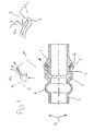
- the device shown in FIG. 1 comprises a first connection section 1 and a second connection section 2, both of which are formed here from an elastomer material.
- the two connection sections 1, 2 are in engagement with one another via a circumferential groove structure 4.
- This circumferential groove structure 4 comprises a circumferential profile formed on the part of the first connection section and an inner profile provided on the second connection section 2 which is complementary thereto.
- the engagement structure arrives in the locked position by means of elastic deformation.
- a discharge device 3 is provided, which here has a plurality of channels spaced apart in the circumferential direction.
- the channels are formed here by groove-like recesses in the area of the inner surface of the second connection section 2.
- the interior defined by the channels is indicated, for example, in the upper sketch K 1 .
- the wave-like course of each channel that can be seen here is determined in particular by the profiling of the outer peripheral surface of the first connection section 1 in the region of the joint.
- an expanding diffuser zone is provided which is formed in a circumferential ring groove and which is provided with a large number of fine steps, by means of which the flow resistance of the diffuser zone is increased still further.
- the diffuser zone in the region of the outer mouths of the channels is filled in such a way that a dynamic pressure zone is created in the inner foot region 6 of the diffuser.
- a suitable cross-sectional design which is also used in the illustrated embodiment, is shown in sketch K 2 .
- the upper wall is formed here by the second connection section 2 and the lower wall by the first wall section 1.
- One of the two connection sections, here the second is provided with a bellows structure 7, by means of which the two connection sections 1, 2 can be tilted, as indicated by the arrow P 1 .
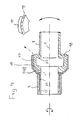
- the derivation device 3 is formed by a plurality of channels 8 which extend outwards in the region of a radially outwardly projecting bead 9 and create a line connection between the inner region 10 and the surroundings U.
- the outflow of the breathing gas takes place here as indicated by the chain line L 1 .
- the channels 8 are formed here in such a way that they first taper in accordance with the increase in the flow velocity and then subsequently open into a diffuser zone.
- the circumferential bead projecting radially outward here is formed integrally with the first connection section 1 from an elastomer material.
- the second connection section 2 is formed by a rotating sleeve arrangement which is rotatably fitted onto the first connection section 1.
- a ring element 11 is provided for this purpose, which is preferably formed from a high-strength material - in particular stainless steel.
- the coupling of the second connection section 2 to the first connection section 1 takes place here via a latching mechanism 12, which is coordinated in such a way that the second connection section 2 can be removed from the first connection section 1 by applying a defined pulling force.
- the alignment of the channels 8 is made here in such a way that the radiation of the derived one Breathing gas takes place along a cone jacket.
- the second connection section 2 is formed here from a plastic material, for example polycarbonate.
- FIG. 3 shows a further embodiment of a device according to the invention, in which, similar to the embodiment according to.
- Fig. 2 shows a radiation the discharged air takes place along a cone shell.
- the channels 8 connect here also the interior 10 with the surroundings U.
- a significant difference compared to the embodiment acc. 2 here consists in the design of the rotating sleeve device, through which a relative rotatability of the second connection section 2 compared to the first connection section 1 is reached.
- a journal member 14 is provided for this purpose in a sealing manner in a corresponding receiving section of the first Connection section 1 is inserted.
- radially resilient locking tongue elements 15 are provided, which are detachable with the tubular sleeve here trained second connection section 2 can be brought into engagement.
- the intensity of the noise events that occur is further reduced by a lamella structure 16 into which the channels 8 open.
- the channels 8 here have an essentially circular cross section and are oriented obliquely to a longitudinal central axis X of the device.
- the radiation angle ⁇ defined with respect to the longitudinal central axis X preferably moves in the range from 10 to 50 °.
- the total cross-sectional area in the area of the narrowest points of the channels 8 is 21 mm 2 in the embodiment shown here.
- FIG. 4 shows a further embodiment of the device according to the invention, in which the channel device 3 in the interaction of a bell-shaped housing part 17 is formed with an elastomer body 18 inserted therein.
- the elastomer body 18 is formed integrally with the first connection section 1 and has a plurality of circumferentially spaced grooves 19.
- the grooves 19 are limited to the outside by the bell-shaped housing part 17 and form corresponding channels 8.
- the coupling of the elastomeric body 18 with the Connection section 1 takes place via a bellows structure 20, which tilts the first Connection section 1 compared to the second connection section 2 allows.
- the second connection section 2 is here about the longitudinal axis X relative to the first connection section rotatable.
- the rotary connection of the second connection section 2 takes place via a socket section 21, which has latching arms 15 which are releasably attached to a corresponding complementary inner peripheral structure of the second connection portion 2 in Intervention can be brought.
- the total cross-sectional area of the channels 8 (here a total of 19 Piece) is 16 mm2.
- first connection section 1 has a plurality of through bores 22 leading radially outwards.
- Ring element 23 is provided in the area of these through bores 22 .
- a socket element which forms the second connection section 2 here. The coupling of the two connection sections 1, 2 is made here such that the second connection section upon application of a predetermined pulling force from the first connection section can be removed.
- a corresponding discharge channel in a gap region which is defined in the interaction of the elastomeric ring element with the body forming the first connection section 1.
- Such channels can be formed, for example, by shallow depressions in the area of the inner circumferential surface of the elastomeric element 23, as is indicated in the sketch K 4 .
- the running length of these channels can be extended, for example, by a labyrinth structure.
- a CPAP machine To perform CPAP therapy to treat sleep-related breathing disorders a CPAP machine is placed next to a patient's bed. To the CPAP device a flexible hose line is connected. To the one facing away from the CPAP device At the end of the hose line is a device for deriving at least partially used breathing gas connected, as shown in particular in Fig. 3 is. For this purpose, the second connection section 2 in the corresponding end of the flexible hose line inserted. Then the first connection section 1 attached to a corresponding connection section of a breathing mask. The breathing mask can now, for example, via a headband arrangement on the nose area of the patient are placed and fixed.
- Rotary mechanism is a direct transmission of any torque the flexible hose line in the breathing mask avoided.
- breathing gas for example filtered ambient air
- Pressure is fed into the flexible hose line.
- the breathing gas flows through the flexible hose line and gets into the breathing mask.
- the breathing gas can now be inhaled by the patient and then exhaled.
- Both during the inhalation process and during the exhalation process air flows permanently over the in the between hose line and mask provided device, in particular via the channels 8 formed here.
- the permanent outflow of breathing gas from the channels makes it permanent Purge of the breathing gas in the area of the breathing mask is reached.
- the radiation of the derived breathing gas via the channels 8 is directed such that the outflowing Airflow does not hit the patient's forehead area.
- the radiation of the Derived breathing gas is particularly quiet, because in addition to a special Favorable piping also the entry of structure-borne noise in the breathing gas piping system is significantly reduced.
Landscapes
- Health & Medical Sciences (AREA)
- Anesthesiology (AREA)
- Life Sciences & Earth Sciences (AREA)
- Engineering & Computer Science (AREA)
- Public Health (AREA)
- Animal Behavior & Ethology (AREA)
- Veterinary Medicine (AREA)
- General Health & Medical Sciences (AREA)
- Emergency Medicine (AREA)
- Pulmonology (AREA)
- Biomedical Technology (AREA)
- Heart & Thoracic Surgery (AREA)
- Hematology (AREA)
- Ecology (AREA)
- Environmental Sciences (AREA)
- Biodiversity & Conservation Biology (AREA)
- Environmental & Geological Engineering (AREA)
- Respiratory Apparatuses And Protective Means (AREA)
- Non-Positive Displacement Air Blowers (AREA)
- Electron Tubes For Measurement (AREA)
- Other Investigation Or Analysis Of Materials By Electrical Means (AREA)
- Infusion, Injection, And Reservoir Apparatuses (AREA)
Applications Claiming Priority (2)
| Application Number | Priority Date | Filing Date | Title |
|---|---|---|---|
| DE10014178 | 2000-03-23 | ||
| DE10014178A DE10014178C2 (de) | 2000-03-23 | 2000-03-23 | Vorrichtung zur Ableitung von Atemgas |
Publications (3)
| Publication Number | Publication Date |
|---|---|
| EP1138340A2 true EP1138340A2 (fr) | 2001-10-04 |
| EP1138340A3 EP1138340A3 (fr) | 2002-10-16 |
| EP1138340B1 EP1138340B1 (fr) | 2004-12-15 |
Family
ID=7635880
Family Applications (1)
| Application Number | Title | Priority Date | Filing Date |
|---|---|---|---|
| EP01105435A Expired - Lifetime EP1138340B1 (fr) | 2000-03-23 | 2001-03-13 | Dispositif pour l'évacuation de gaz respiratoire |
Country Status (3)
| Country | Link |
|---|---|
| EP (1) | EP1138340B1 (fr) |
| AT (1) | ATE284728T1 (fr) |
| DE (2) | DE10014178C2 (fr) |
Cited By (14)
| Publication number | Priority date | Publication date | Assignee | Title |
|---|---|---|---|---|
| EP1362610A1 (fr) * | 2002-05-14 | 2003-11-19 | Gottlieb Weinmann Geräte für Medizin und Arbeitsschutz GmbH & Co.KG | Dispositif pour l'évacuation de gaz respiratoire |
| WO2006015772A1 (fr) * | 2004-08-02 | 2006-02-16 | Map Medizin-Technologie Gmbh | Dispositif pour evacuer du gaz respiratoire de l'interieur d'un masque respiratoire, ainsi qu'ensemble masque respiratoire comprenant ce dispositif |
| WO2008058506A2 (fr) | 2006-11-14 | 2008-05-22 | Dräger Medical AG & Co. KG | Dispositif de raccordement de flexible respiratoire |
| GB2454446A (en) * | 2008-07-29 | 2009-05-13 | Draeger Medical Ag | Device for allowing a bypass flow of respiratory gas |
| CN103285484A (zh) * | 2012-03-01 | 2013-09-11 | 德尔格医疗有限责任公司 | 气体联接装置 |
| US8783298B2 (en) | 2009-07-29 | 2014-07-22 | Kast Silicone Ltd. | Breathing hose |
| EP2178590A4 (fr) * | 2007-07-18 | 2015-07-22 | Vapotherm Inc | Système et procédé d'administration de gaz réchauffé et humidifié |
| US10398871B2 (en) | 2015-03-31 | 2019-09-03 | Vapotherm, Inc. | Systems and methods for patient-proximate vapor transfer for respiratory therapy |
| US10596345B2 (en) | 2014-12-31 | 2020-03-24 | Vapotherm, Inc. | Systems and methods for humidity control |
| WO2020151827A1 (fr) * | 2019-01-24 | 2020-07-30 | Wilamed Gmbh | Valve à fuite intentionnelle ainsi que système de tubes respiratoires |
| US10894141B2 (en) | 2007-10-05 | 2021-01-19 | Vapotherm, Inc. | Hyperthermic humidification system |
| US11351330B2 (en) | 2016-10-14 | 2022-06-07 | Vapotherm, Inc. | Systems and methods for high velocity nasal insufflation |
| US20220339386A1 (en) * | 2008-03-04 | 2022-10-27 | ResMed Pty Ltd | Mask system |
| US12064562B2 (en) | 2020-03-12 | 2024-08-20 | Vapotherm, Inc. | Respiratory therapy unit with non-contact sensing and control |
Families Citing this family (2)
| Publication number | Priority date | Publication date | Assignee | Title |
|---|---|---|---|---|
| DE102004037344A1 (de) * | 2004-08-02 | 2006-03-16 | Map Medizin-Technologie Gmbh | Vorrichtung zur Ableitung von Atemgas aus dem Innenbereich einer Atemmaske, sowie unter Einschluss dieser Vorrichtung gebildete Atemmaskenanordnung |
| DE102005001247B4 (de) * | 2005-01-11 | 2016-04-07 | Resmed R&D Germany Gmbh | Vorrichtung zur Ableitung von Atemgas |
Citations (1)
| Publication number | Priority date | Publication date | Assignee | Title |
|---|---|---|---|---|
| DE19840760A1 (de) | 1998-09-07 | 2000-03-09 | Map Medizintechnik Gmbh | Schalldämpfer für Beatmungsvorrichtung |
Family Cites Families (5)
| Publication number | Priority date | Publication date | Assignee | Title |
|---|---|---|---|---|
| DE9411933U1 (de) * | 1994-07-22 | 1994-10-27 | Gottlieb Weinmann Geräte für Medizin und Arbeitsschutz GmbH + Co, 22525 Hamburg | Gaszuführleitung |
| US5762382A (en) * | 1996-07-12 | 1998-06-09 | Ohmeda Inc. | Interlocking dual seal cuff/port interface |
| AUPO504597A0 (en) * | 1997-02-10 | 1997-03-06 | Resmed Limited | A mask and a vent assembly therefor |
| US5937851A (en) * | 1997-02-27 | 1999-08-17 | Respironics, Inc. | Swivel device utilizing bearing clearance to allow carbon dioxide laden exhaust |
| DE19757703C5 (de) * | 1997-12-23 | 2009-09-17 | Map Medizin-Technologie Gmbh | Beatmungsvorrichtung |
-
2000
- 2000-03-23 DE DE10014178A patent/DE10014178C2/de not_active Expired - Lifetime
-
2001
- 2001-03-13 DE DE50104799T patent/DE50104799D1/de not_active Expired - Lifetime
- 2001-03-13 EP EP01105435A patent/EP1138340B1/fr not_active Expired - Lifetime
- 2001-03-13 AT AT01105435T patent/ATE284728T1/de not_active IP Right Cessation
Patent Citations (1)
| Publication number | Priority date | Publication date | Assignee | Title |
|---|---|---|---|---|
| DE19840760A1 (de) | 1998-09-07 | 2000-03-09 | Map Medizintechnik Gmbh | Schalldämpfer für Beatmungsvorrichtung |
Cited By (36)
| Publication number | Priority date | Publication date | Assignee | Title |
|---|---|---|---|---|
| EP1362610A1 (fr) * | 2002-05-14 | 2003-11-19 | Gottlieb Weinmann Geräte für Medizin und Arbeitsschutz GmbH & Co.KG | Dispositif pour l'évacuation de gaz respiratoire |
| WO2006015772A1 (fr) * | 2004-08-02 | 2006-02-16 | Map Medizin-Technologie Gmbh | Dispositif pour evacuer du gaz respiratoire de l'interieur d'un masque respiratoire, ainsi qu'ensemble masque respiratoire comprenant ce dispositif |
| JP2008508069A (ja) * | 2004-08-02 | 2008-03-21 | エムアーペー・メディツィーン−テヒノロギー・ゲゼルシャフト・ミット・ベシュレンクテル・ハフツング | 呼吸マスクの内部から呼吸ガスの流れを変えるための装置、及び該装置を含むことにより形成された呼吸マスク配置 |
| US8496004B2 (en) | 2004-08-02 | 2013-07-30 | Resmed R&D Germany Gmbh | Device for evacuating breathing gas from the interior of a breathing mask, and breathing mask arrangement comprising said device |
| JP4928453B2 (ja) * | 2004-08-02 | 2012-05-09 | エムアーペー・メディツィーン−テヒノロギー・ゲゼルシャフト・ミット・ベシュレンクテル・ハフツング | 呼吸マスクの内部から呼吸ガスの流れを変えるための装置、及び該装置を含むことにより形成された呼吸マスク配置 |
| WO2008058506A2 (fr) | 2006-11-14 | 2008-05-22 | Dräger Medical AG & Co. KG | Dispositif de raccordement de flexible respiratoire |
| WO2008058506A3 (fr) * | 2006-11-14 | 2008-08-14 | Draeger Medical Ag | Dispositif de raccordement de flexible respiratoire |
| US8739778B2 (en) | 2006-11-14 | 2014-06-03 | Dräger Medical GmbH | Breathing tube connecting device |
| US12226585B2 (en) | 2007-07-18 | 2025-02-18 | Vapotherm, Inc. | Humidifier for breathing gas heating and humidification system |
| US10786646B2 (en) | 2007-07-18 | 2020-09-29 | Vapotherm, Inc. | Humidifier for breathing gas heating and humidification system |
| US11103670B2 (en) | 2007-07-18 | 2021-08-31 | Vapotherm, Inc. | Humidifier for breathing gas heating and humidification system |
| US10974016B1 (en) | 2007-07-18 | 2021-04-13 | Vapotherm, Inc. | Humidifier for breathing gas heating and humidification system |
| EP2178590A4 (fr) * | 2007-07-18 | 2015-07-22 | Vapotherm Inc | Système et procédé d'administration de gaz réchauffé et humidifié |
| US10918822B2 (en) | 2007-07-18 | 2021-02-16 | Vapotherm, Inc. | Humidifier for breathing gas heating and humidification system |
| US11648368B2 (en) | 2007-10-05 | 2023-05-16 | Vapotherm, Inc. | Hyperthermic humidification system |
| US10974014B2 (en) | 2007-10-05 | 2021-04-13 | Vapotherm, Inc. | Hyperthermic humidification system |
| US12268817B2 (en) | 2007-10-05 | 2025-04-08 | Vapotherm, Inc. | Hyperthermic humidification system |
| US10894141B2 (en) | 2007-10-05 | 2021-01-19 | Vapotherm, Inc. | Hyperthermic humidification system |
| US10974013B2 (en) | 2007-10-05 | 2021-04-13 | Vapotherm, Inc. | Hyperthermic humidification system |
| US10933212B2 (en) | 2007-10-05 | 2021-03-02 | Vapotherm, Inc. | Hyperthermic humidification system |
| US20220339386A1 (en) * | 2008-03-04 | 2022-10-27 | ResMed Pty Ltd | Mask system |
| US12208208B2 (en) | 2008-03-04 | 2025-01-28 | ResMed Pty Ltd | Mask system with shroud and vent holes |
| US11969552B2 (en) * | 2008-03-04 | 2024-04-30 | ResMed Pty Ltd | Mask system with radially positioned vent holes |
| GB2454446B (en) * | 2008-07-29 | 2009-10-07 | Draeger Medical Ag | Device for discharging respiratory gas |
| GB2454446A (en) * | 2008-07-29 | 2009-05-13 | Draeger Medical Ag | Device for allowing a bypass flow of respiratory gas |
| US8783298B2 (en) | 2009-07-29 | 2014-07-22 | Kast Silicone Ltd. | Breathing hose |
| CN103285484A (zh) * | 2012-03-01 | 2013-09-11 | 德尔格医疗有限责任公司 | 气体联接装置 |
| US10596345B2 (en) | 2014-12-31 | 2020-03-24 | Vapotherm, Inc. | Systems and methods for humidity control |
| US12053588B2 (en) | 2014-12-31 | 2024-08-06 | Vapotherm, Inc. | Systems and methods for humidity control |
| US10398871B2 (en) | 2015-03-31 | 2019-09-03 | Vapotherm, Inc. | Systems and methods for patient-proximate vapor transfer for respiratory therapy |
| US11497880B2 (en) | 2015-03-31 | 2022-11-15 | Vapotherm, Inc. | Systems and methods for patient-proximate vapor transfer for respiratory therapy |
| US11351330B2 (en) | 2016-10-14 | 2022-06-07 | Vapotherm, Inc. | Systems and methods for high velocity nasal insufflation |
| US12599742B2 (en) | 2016-10-14 | 2026-04-14 | Vapotherm, Inc. | Systems and methods for high velocity nasal insufflation |
| WO2020151827A1 (fr) * | 2019-01-24 | 2020-07-30 | Wilamed Gmbh | Valve à fuite intentionnelle ainsi que système de tubes respiratoires |
| US12569641B2 (en) | 2019-01-24 | 2026-03-10 | Wilamed Gmbh | Leakage valve and ventilation tube system |
| US12064562B2 (en) | 2020-03-12 | 2024-08-20 | Vapotherm, Inc. | Respiratory therapy unit with non-contact sensing and control |
Also Published As
| Publication number | Publication date |
|---|---|
| ATE284728T1 (de) | 2005-01-15 |
| DE10014178A1 (de) | 2001-09-27 |
| EP1138340A3 (fr) | 2002-10-16 |
| EP1138340B1 (fr) | 2004-12-15 |
| DE50104799D1 (de) | 2005-01-20 |
| DE10014178C2 (de) | 2003-04-10 |
Similar Documents
| Publication | Publication Date | Title |
|---|---|---|
| EP1138340B1 (fr) | Dispositif pour l'évacuation de gaz respiratoire | |
| DE60023291T2 (de) | Anschluss für eine atemmaske | |
| DE69839041T2 (de) | Maske und entlüftungsvorrichtung dafür | |
| DE20005346U1 (de) | Vorrichtung zur Ableitung von Atemgas | |
| EP1838372B1 (fr) | Masque respiratoire | |
| DE69305952T2 (de) | Ansaugkatheteranordnungen | |
| DE10126808C1 (de) | Inhalationsmaske | |
| EP2075025B1 (fr) | Masque respiratoire ayant un évent | |
| DE4208912C1 (fr) | ||
| DE69005086T2 (de) | Sprecheinrichtung zum gebrauch bei sauerstoffversorgung. | |
| DE19962110C2 (de) | Inhalationsvernebler mit einstückigem Ventilelement | |
| DE19508512A1 (de) | Saugkatheter | |
| EP2489413B1 (fr) | Appareil de thérapie | |
| EP1314446A2 (fr) | Masque respiratoire | |
| DE4434569A1 (de) | Kathetereinführvorrichtung mit Blutdichtung | |
| EP3624883B1 (fr) | Soupape d'expiration d'un dispositif respiratoire avec résistance à l'écoulement minimisant les bruits | |
| DE10046872B4 (de) | Atmungsunterstützungsvorrichtung | |
| DE102019117734A1 (de) | Atemmaske und Verfahren zur Herstellung einer Atemmaske | |
| DE102005041717B4 (de) | Atemmaske mit Strömungsleitstrukturen | |
| EP1776153B1 (fr) | Dispositif pour evacuer du gaz respiratoire de l'interieur d'un masque respiratoire, ainsi qu'ensemble masque respiratoire comprenant ce dispositif | |
| DE19757703C5 (de) | Beatmungsvorrichtung | |
| DE69929160T2 (de) | Zweiweg Ventilvorrichtung | |
| EP1174159A2 (fr) | Dispositif d'alimentation en gaz respiratoire | |
| EP3144026A1 (fr) | Masque respiratoire en plusieurs partie, element d'obturation du nez associe et combinaison associee d'un element de raccord de tuyau et un element de couplage | |
| DE10051897C1 (de) | Atemmaske zur Zufuhr eines Atemgases zu einem Maskenanwender sowie Ableitungseinrichtung zur Ableitung von Atemgas |
Legal Events
| Date | Code | Title | Description |
|---|---|---|---|
| PUAI | Public reference made under article 153(3) epc to a published international application that has entered the european phase |
Free format text: ORIGINAL CODE: 0009012 |
|
| AK | Designated contracting states |
Kind code of ref document: A2 Designated state(s): AT BE CH CY DE DK ES FI FR GB GR IE IT LI LU MC NL PT SE TR |
|
| AX | Request for extension of the european patent |
Free format text: AL;LT;LV;MK;RO;SI |
|
| PUAL | Search report despatched |
Free format text: ORIGINAL CODE: 0009013 |
|
| AK | Designated contracting states |
Kind code of ref document: A3 Designated state(s): AT BE CH CY DE DK ES FI FR GB GR IE IT LI LU MC NL PT SE TR |
|
| AX | Request for extension of the european patent |
Free format text: AL;LT;LV;MK;RO;SI |
|
| 17P | Request for examination filed |
Effective date: 20030415 |
|
| AKX | Designation fees paid |
Designated state(s): AT BE CH CY DE DK ES FI FR GB GR IE IT LI LU MC NL PT SE TR |
|
| 17Q | First examination report despatched |
Effective date: 20030611 |
|
| GRAP | Despatch of communication of intention to grant a patent |
Free format text: ORIGINAL CODE: EPIDOSNIGR1 |
|
| GRAS | Grant fee paid |
Free format text: ORIGINAL CODE: EPIDOSNIGR3 |
|
| RAP1 | Party data changed (applicant data changed or rights of an application transferred) |
Owner name: MAP MEDIZIN-TECHNOLOGIE GMBH |
|
| GRAA | (expected) grant |
Free format text: ORIGINAL CODE: 0009210 |
|
| AK | Designated contracting states |
Kind code of ref document: B1 Designated state(s): AT BE CH CY DE DK ES FI FR GB GR IE IT LI LU MC NL PT SE TR |
|
| PG25 | Lapsed in a contracting state [announced via postgrant information from national office to epo] |
Ref country code: IT Free format text: LAPSE BECAUSE OF FAILURE TO SUBMIT A TRANSLATION OF THE DESCRIPTION OR TO PAY THE FEE WITHIN THE PRESCRIBED TIME-LIMIT;WARNING: LAPSES OF ITALIAN PATENTS WITH EFFECTIVE DATE BEFORE 2007 MAY HAVE OCCURRED AT ANY TIME BEFORE 2007. THE CORRECT EFFECTIVE DATE MAY BE DIFFERENT FROM THE ONE RECORDED. Effective date: 20041215 Ref country code: FI Free format text: LAPSE BECAUSE OF FAILURE TO SUBMIT A TRANSLATION OF THE DESCRIPTION OR TO PAY THE FEE WITHIN THE PRESCRIBED TIME-LIMIT Effective date: 20041215 Ref country code: ES Free format text: LAPSE BECAUSE OF FAILURE TO SUBMIT A TRANSLATION OF THE DESCRIPTION OR TO PAY THE FEE WITHIN THE PRESCRIBED TIME-LIMIT Effective date: 20041215 Ref country code: IE Free format text: LAPSE BECAUSE OF FAILURE TO SUBMIT A TRANSLATION OF THE DESCRIPTION OR TO PAY THE FEE WITHIN THE PRESCRIBED TIME-LIMIT Effective date: 20041215 Ref country code: NL Free format text: LAPSE BECAUSE OF FAILURE TO SUBMIT A TRANSLATION OF THE DESCRIPTION OR TO PAY THE FEE WITHIN THE PRESCRIBED TIME-LIMIT Effective date: 20041215 Ref country code: TR Free format text: LAPSE BECAUSE OF FAILURE TO SUBMIT A TRANSLATION OF THE DESCRIPTION OR TO PAY THE FEE WITHIN THE PRESCRIBED TIME-LIMIT Effective date: 20041215 |
|
| REG | Reference to a national code |
Ref country code: GB Ref legal event code: FG4D Free format text: NOT ENGLISH Ref country code: CH Ref legal event code: EP |
|
| GBT | Gb: translation of ep patent filed (gb section 77(6)(a)/1977) |
Effective date: 20041215 |
|
| REG | Reference to a national code |
Ref country code: IE Ref legal event code: FG4D Free format text: GERMAN |
|
| REF | Corresponds to: |
Ref document number: 50104799 Country of ref document: DE Date of ref document: 20050120 Kind code of ref document: P |
|
| PG25 | Lapsed in a contracting state [announced via postgrant information from national office to epo] |
Ref country code: LU Free format text: LAPSE BECAUSE OF NON-PAYMENT OF DUE FEES Effective date: 20050313 Ref country code: CY Free format text: LAPSE BECAUSE OF FAILURE TO SUBMIT A TRANSLATION OF THE DESCRIPTION OR TO PAY THE FEE WITHIN THE PRESCRIBED TIME-LIMIT Effective date: 20050313 Ref country code: AT Free format text: LAPSE BECAUSE OF NON-PAYMENT OF DUE FEES Effective date: 20050313 |
|
| PG25 | Lapsed in a contracting state [announced via postgrant information from national office to epo] |
Ref country code: SE Free format text: LAPSE BECAUSE OF FAILURE TO SUBMIT A TRANSLATION OF THE DESCRIPTION OR TO PAY THE FEE WITHIN THE PRESCRIBED TIME-LIMIT Effective date: 20050315 Ref country code: GR Free format text: LAPSE BECAUSE OF FAILURE TO SUBMIT A TRANSLATION OF THE DESCRIPTION OR TO PAY THE FEE WITHIN THE PRESCRIBED TIME-LIMIT Effective date: 20050315 Ref country code: DK Free format text: LAPSE BECAUSE OF FAILURE TO SUBMIT A TRANSLATION OF THE DESCRIPTION OR TO PAY THE FEE WITHIN THE PRESCRIBED TIME-LIMIT Effective date: 20050315 |
|
| PG25 | Lapsed in a contracting state [announced via postgrant information from national office to epo] |
Ref country code: LI Free format text: LAPSE BECAUSE OF NON-PAYMENT OF DUE FEES Effective date: 20050331 Ref country code: BE Free format text: LAPSE BECAUSE OF NON-PAYMENT OF DUE FEES Effective date: 20050331 Ref country code: CH Free format text: LAPSE BECAUSE OF NON-PAYMENT OF DUE FEES Effective date: 20050331 Ref country code: MC Free format text: LAPSE BECAUSE OF NON-PAYMENT OF DUE FEES Effective date: 20050331 |
|
| NLV1 | Nl: lapsed or annulled due to failure to fulfill the requirements of art. 29p and 29m of the patents act | ||
| REG | Reference to a national code |
Ref country code: IE Ref legal event code: FD4D |
|
| BERE | Be: lapsed |
Owner name: MAP MEDIZIN-TECHNOLOGIE G.M.B.H. Effective date: 20050331 |
|
| PLBE | No opposition filed within time limit |
Free format text: ORIGINAL CODE: 0009261 |
|
| STAA | Information on the status of an ep patent application or granted ep patent |
Free format text: STATUS: NO OPPOSITION FILED WITHIN TIME LIMIT |
|
| REG | Reference to a national code |
Ref country code: CH Ref legal event code: PL |
|
| 26N | No opposition filed |
Effective date: 20050916 |
|
| ET | Fr: translation filed | ||
| BERE | Be: lapsed |
Owner name: *MAP MEDIZIN-TECHNOLOGIE G.M.B.H. Effective date: 20050331 |
|
| PG25 | Lapsed in a contracting state [announced via postgrant information from national office to epo] |
Ref country code: PT Free format text: LAPSE BECAUSE OF NON-PAYMENT OF DUE FEES Effective date: 20050515 |
|
| REG | Reference to a national code |
Ref country code: DE Ref legal event code: R081 Ref document number: 50104799 Country of ref document: DE Owner name: RESMED R&D GERMANY GMBH, DE Free format text: FORMER OWNER: MAP MEDIZIN-TECHNOLOGIE GMBH, 82152 PLANEGG, DE Effective date: 20130221 Ref country code: DE Ref legal event code: R082 Ref document number: 50104799 Country of ref document: DE Representative=s name: VOSSIUS & PARTNER, DE Effective date: 20130221 Ref country code: DE Ref legal event code: R082 Ref document number: 50104799 Country of ref document: DE Representative=s name: VOSSIUS & PARTNER PATENTANWAELTE RECHTSANWAELT, DE Effective date: 20130221 |
|
| REG | Reference to a national code |
Ref country code: FR Ref legal event code: CD Owner name: RESMED R&D GERMANY GMBH Effective date: 20141003 |
|
| REG | Reference to a national code |
Ref country code: FR Ref legal event code: PLFP Year of fee payment: 16 |
|
| REG | Reference to a national code |
Ref country code: FR Ref legal event code: PLFP Year of fee payment: 17 |
|
| REG | Reference to a national code |
Ref country code: FR Ref legal event code: PLFP Year of fee payment: 18 |
|
| PGFP | Annual fee paid to national office [announced via postgrant information from national office to epo] |
Ref country code: GB Payment date: 20200304 Year of fee payment: 20 Ref country code: DE Payment date: 20200303 Year of fee payment: 20 |
|
| PGFP | Annual fee paid to national office [announced via postgrant information from national office to epo] |
Ref country code: FR Payment date: 20200214 Year of fee payment: 20 |
|
| REG | Reference to a national code |
Ref country code: DE Ref legal event code: R071 Ref document number: 50104799 Country of ref document: DE |
|
| REG | Reference to a national code |
Ref country code: GB Ref legal event code: PE20 Expiry date: 20210312 |
|
| PG25 | Lapsed in a contracting state [announced via postgrant information from national office to epo] |
Ref country code: GB Free format text: LAPSE BECAUSE OF EXPIRATION OF PROTECTION Effective date: 20210312 |