EP1138454A2 - Vorrichtung zur Trennung der Befestigungspunkte, die zwei Ränder einer Schnittlinie verbinden - Google Patents
Vorrichtung zur Trennung der Befestigungspunkte, die zwei Ränder einer Schnittlinie verbinden Download PDFInfo
- Publication number
- EP1138454A2 EP1138454A2 EP01106872A EP01106872A EP1138454A2 EP 1138454 A2 EP1138454 A2 EP 1138454A2 EP 01106872 A EP01106872 A EP 01106872A EP 01106872 A EP01106872 A EP 01106872A EP 1138454 A2 EP1138454 A2 EP 1138454A2
- Authority
- EP
- European Patent Office
- Prior art keywords
- tool
- shafts
- tools
- supports
- annular
- Prior art date
- Legal status (The legal status is an assumption and is not a legal conclusion. Google has not performed a legal analysis and makes no representation as to the accuracy of the status listed.)
- Granted
Links
Images




Classifications
-
- B—PERFORMING OPERATIONS; TRANSPORTING
- B26—HAND CUTTING TOOLS; CUTTING; SEVERING
- B26D—CUTTING; DETAILS COMMON TO MACHINES FOR PERFORATING, PUNCHING, CUTTING-OUT, STAMPING-OUT OR SEVERING
- B26D7/00—Details of apparatus for cutting, cutting-out, stamping-out, punching, perforating, or severing by means other than cutting
- B26D7/18—Means for removing cut-out material or waste
- B26D7/1818—Means for removing cut-out material or waste by pushing out
-
- B—PERFORMING OPERATIONS; TRANSPORTING
- B26—HAND CUTTING TOOLS; CUTTING; SEVERING
- B26D—CUTTING; DETAILS COMMON TO MACHINES FOR PERFORATING, PUNCHING, CUTTING-OUT, STAMPING-OUT OR SEVERING
- B26D5/00—Arrangements for operating and controlling machines or devices for cutting, cutting-out, stamping-out, punching, perforating, or severing by means other than cutting
- B26D5/20—Arrangements for operating and controlling machines or devices for cutting, cutting-out, stamping-out, punching, perforating, or severing by means other than cutting with interrelated action between the cutting member and work feed
- B26D5/26—Arrangements for operating and controlling machines or devices for cutting, cutting-out, stamping-out, punching, perforating, or severing by means other than cutting with interrelated action between the cutting member and work feed wherein control means on the work feed means renders the cutting member operative
- B26D5/28—Arrangements for operating and controlling machines or devices for cutting, cutting-out, stamping-out, punching, perforating, or severing by means other than cutting with interrelated action between the cutting member and work feed wherein control means on the work feed means renders the cutting member operative the control means being responsive to presence or absence of work
-
- B—PERFORMING OPERATIONS; TRANSPORTING
- B26—HAND CUTTING TOOLS; CUTTING; SEVERING
- B26D—CUTTING; DETAILS COMMON TO MACHINES FOR PERFORATING, PUNCHING, CUTTING-OUT, STAMPING-OUT OR SEVERING
- B26D5/00—Arrangements for operating and controlling machines or devices for cutting, cutting-out, stamping-out, punching, perforating, or severing by means other than cutting
- B26D5/20—Arrangements for operating and controlling machines or devices for cutting, cutting-out, stamping-out, punching, perforating, or severing by means other than cutting with interrelated action between the cutting member and work feed
- B26D5/30—Arrangements for operating and controlling machines or devices for cutting, cutting-out, stamping-out, punching, perforating, or severing by means other than cutting with interrelated action between the cutting member and work feed having the cutting member controlled by scanning a record carrier
- B26D5/34—Arrangements for operating and controlling machines or devices for cutting, cutting-out, stamping-out, punching, perforating, or severing by means other than cutting with interrelated action between the cutting member and work feed having the cutting member controlled by scanning a record carrier scanning being effected by a photosensitive device
-
- B—PERFORMING OPERATIONS; TRANSPORTING
- B26—HAND CUTTING TOOLS; CUTTING; SEVERING
- B26F—PERFORATING; PUNCHING; CUTTING-OUT; STAMPING-OUT; SEVERING BY MEANS OTHER THAN CUTTING
- B26F3/00—Severing by means other than cutting; Apparatus therefor
- B26F3/002—Precutting and tensioning or breaking
-
- Y—GENERAL TAGGING OF NEW TECHNOLOGICAL DEVELOPMENTS; GENERAL TAGGING OF CROSS-SECTIONAL TECHNOLOGIES SPANNING OVER SEVERAL SECTIONS OF THE IPC; TECHNICAL SUBJECTS COVERED BY FORMER USPC CROSS-REFERENCE ART COLLECTIONS [XRACs] AND DIGESTS
- Y10—TECHNICAL SUBJECTS COVERED BY FORMER USPC
- Y10T—TECHNICAL SUBJECTS COVERED BY FORMER US CLASSIFICATION
- Y10T225/00—Severing by tearing or breaking
- Y10T225/30—Breaking or tearing apparatus
- Y10T225/371—Movable breaking tool
-
- Y—GENERAL TAGGING OF NEW TECHNOLOGICAL DEVELOPMENTS; GENERAL TAGGING OF CROSS-SECTIONAL TECHNOLOGIES SPANNING OVER SEVERAL SECTIONS OF THE IPC; TECHNICAL SUBJECTS COVERED BY FORMER USPC CROSS-REFERENCE ART COLLECTIONS [XRACs] AND DIGESTS
- Y10—TECHNICAL SUBJECTS COVERED BY FORMER USPC
- Y10T—TECHNICAL SUBJECTS COVERED BY FORMER US CLASSIFICATION
- Y10T225/00—Severing by tearing or breaking
- Y10T225/30—Breaking or tearing apparatus
- Y10T225/371—Movable breaking tool
- Y10T225/379—Breaking tool intermediate spaced work supports
-
- Y—GENERAL TAGGING OF NEW TECHNOLOGICAL DEVELOPMENTS; GENERAL TAGGING OF CROSS-SECTIONAL TECHNOLOGIES SPANNING OVER SEVERAL SECTIONS OF THE IPC; TECHNICAL SUBJECTS COVERED BY FORMER USPC CROSS-REFERENCE ART COLLECTIONS [XRACs] AND DIGESTS
- Y10—TECHNICAL SUBJECTS COVERED BY FORMER USPC
- Y10T—TECHNICAL SUBJECTS COVERED BY FORMER US CLASSIFICATION
- Y10T83/00—Cutting
- Y10T83/465—Cutting motion of tool has component in direction of moving work
- Y10T83/4766—Orbital motion of cutting blade
- Y10T83/4795—Rotary tool
- Y10T83/4798—Segmented disc slitting or slotting tool
-
- Y—GENERAL TAGGING OF NEW TECHNOLOGICAL DEVELOPMENTS; GENERAL TAGGING OF CROSS-SECTIONAL TECHNOLOGIES SPANNING OVER SEVERAL SECTIONS OF THE IPC; TECHNICAL SUBJECTS COVERED BY FORMER USPC CROSS-REFERENCE ART COLLECTIONS [XRACs] AND DIGESTS
- Y10—TECHNICAL SUBJECTS COVERED BY FORMER USPC
- Y10T—TECHNICAL SUBJECTS COVERED BY FORMER US CLASSIFICATION
- Y10T83/00—Cutting
- Y10T83/768—Rotatable disc tool pair or tool and carrier
- Y10T83/7809—Tool pair comprises rotatable tools
- Y10T83/7813—Tool pair elements angularly related
- Y10T83/7818—Elements of tool pair angularly adjustable relative to each other
-
- Y—GENERAL TAGGING OF NEW TECHNOLOGICAL DEVELOPMENTS; GENERAL TAGGING OF CROSS-SECTIONAL TECHNOLOGIES SPANNING OVER SEVERAL SECTIONS OF THE IPC; TECHNICAL SUBJECTS COVERED BY FORMER USPC CROSS-REFERENCE ART COLLECTIONS [XRACs] AND DIGESTS
- Y10—TECHNICAL SUBJECTS COVERED BY FORMER USPC
- Y10T—TECHNICAL SUBJECTS COVERED BY FORMER US CLASSIFICATION
- Y10T83/00—Cutting
- Y10T83/768—Rotatable disc tool pair or tool and carrier
- Y10T83/7872—Tool element mounted for adjustment
Definitions
- the present invention relates to a device for breaking attachment points connecting two edges of a cutting line formed on cardboard blanks before folding, including a frame bearing means for transporting said blanks along a trajectory substantially flat and two parallel shafts, rotatably mounted on one side and on the other side of the plane of said trajectory, comprising tools for inducing a shear between the edges adjacent to said cutting line during their displacement, in order to break said attachment points.
- a neighboring device has already been proposed, for example, in the patent EP 0 680 821.
- This device is intended more particularly to break the fibers of cardboard which may accidentally remain in cutouts whose different panels are separated by simple cutting lines.
- the problem to be solved is, however, quite comparable to that discussed above.
- the object of the present invention is to remedy, at least by part, to the disadvantages of the aforementioned device.
- the subject of this invention is a device as defined by claim 1.
- This device allows it in particular a great flexibility of use and adaptation to cardboard cutouts dimensions likely to vary significantly. This new design also makes it easier to adjust the position of the tools, allowing to increase productivity.
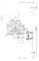
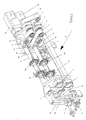
- the device illustrated by Figures 1-3 has a frame formed essentially of two vertical parts, left and right, respectively 1 and 2, kept apart from each other by several spacers 3.
- Two cradles, one upper 4a, the other lower 5a, are associated to the left part 1 of the frame and two other cradles, upper 4b, lower 5b are associated with the right part 2 of the frame.
- Each of these cradles 4a, 5a is pivotally mounted on the left part 1 of the frame by a pivot axis 6, respectively 7.
- Each of the cradles 4b, 5b is pivotally mounted on the part straight 2 of the frame by a pivot axis 8, respectively 9.
- the two upper cradles 4a, 4b carry a first tool-holding shaft 10, while the two lower cradles 5a, 5b carry a second tool-carrying shaft 11.
- the two upper cradles 4a, 4b are associated with a device adjustment 12 worm screw, acting on two connecting rods 12a, 12b connected to ends of the respective cradles 4a, 4b opposite the pivot shafts 6, 8 and intended to pivot these upper cradles 4a, 4b around these pivot axes 6, 8.
- Another similar adjustment device 13 makes it possible to rotate the lower cradles 5a, 5b around the pivot axes 7, 9, by means of two connecting rods 13a, 13b.
- Each tool-holder shaft 10, 11 is integral with a motor synchronous drive M1, respectively M2.
- the tool shafts 10, 11 are kinematically connected to coaxial shafts 14, respectively 15 to the pivot axes 8, 9 of the cradles 4b, 5b, by toothed belts 16, respectively 17.
- the shafts 14, 15 cross the straight part 2 of the frame, as can be seen in Figure 2, to extend on both sides of this right part 2.
- the external portions of the shafts 14, 15 are connected kinematically by a belt 18 notched on its two faces, so that the angular positions of the two tool shafts 10, 11 are constantly synchronous.
- one of the motors M1, M2 must be controlled to the other. In this example, it is the motor M1 which is slaved to the motor M2.
- the control device will be described in relation to FIG. 6.
- Each tool shaft 10, 11 is provided with a keyway 10a, 11a for the angular positioning of annular tool supports 19a, 19b, 20a, 20b.
- These tool holders always go in pairs and face each other, the tools of a tool support 19a secured to the upper tool holder shaft 10 cooperating with the tools of the tool support 19b, integral with the tool-holder shaft lower 11.
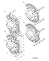
- annular tool supports 19a, 19b, 20a, 20b are illustrated in on a larger scale in FIG. 4. Only one of them 19b will be described here in detail, since they are all identical.
- This tool support 19b includes a discoidal ring 21 in the shape of a circular sector, the angular opening of which is dimensioned to allow the passage of one of the tool-holder shafts 10, 11.
- the discoid rings 21 of two tool supports 19a, 19b of the same pair are intended to be coplanar, i.e. they will be positioned to occupy the same axial positions along their tool shafts respective, 10, 11.
- the discoidal ring 21 is integral with a first half collar of clamping 22 of diameter corresponding to that of said tool-holder shafts 10, 11, provided with an internal groove 22a intended to cooperate with one of the grooves of key 10a, 11a of the tool-holding shafts 10, 11.
- a second half collar of clamping 23 of diameter corresponding to that of said tool-holder shafts 10, 11, connected to the first half clamp 22 by two clamping screws 24, 25, allows to axially immobilize the tool support 19b along the tool holder shaft 11 by clamping this shaft between the two half clamps 22, 23.
- the discoidal ring 21 has a positioning projection annular 21a, pierced with a plurality of openings in an arc 26 coaxial to the discoid ring 21.
- a similar annular positioning projection and of the same diameter as the projection 21a (not visible) is formed on the other face of the discoid ring 21.
- Different tools 27 for breaking the attachment points connecting two edges of a cutting line of a cardboard blank are angularly positioned along these annular projections thanks to shoes positioning 27a in which is formed a groove of positioning 27b intended to come into engagement with the annular projection 21a.
- part of the tools 27 extends on one side of the median plane of the discoid ring 21, while the other part of these tools extends on the other side of this same median plane.
- the tools 27 of two tool supports 19a, 19b of the same pair of supports of tools that extend from one side of this midplane and those that extend from the other side of this median plane describe two parallel circular paths and adjacent, since the discoid rings 21 of the two tool supports 19a, 19b are coplanar.
- peripheral edges of some of these tools 27 describe larger circular paths diameters than the peripheral edges of other tools 27.
- the trajectories of smaller diameter of the peripheral edges of the tools 27 are chosen for be substantially tangent to the planar trajectories of the cuts displaced by the transport device which will be described later, so that these tools 27 play a role in supporting the cuts.
- Edges peripherals of other tools 27, whose trajectories are larger diameters, are adjusted to penetrate the planar trajectory of the cutouts carton transported by the transporter.
- the transport mechanism which will now be described is disposed between the left 1 and right 2 parts of the frame. As the situation of this mechanism would make it difficult to see, it is shown separately to make the drawing easier to read. It has a lower part 30 and two upper parts 31a, 31b.
- the lower part has a band endless conveyor 32 guided by a plurality of rollers 33 and driven by a motor 34. Part of the rollers 33 are arranged in a plane corresponding to the transport path of the cardboard blanks.
- the strip endless conveyor 32 is guided by a series of rollers 33a, for form a loop 32a extending below the plane of the trajectory of transport.
- This loop 32a provides space corresponding to the size of the tool support 19b carried by the lower tool shaft 11.
- the loop 32a is shown closed, its two ends 32b joining substantially at the point of tangency of the strip conveyor 32 with the circular path of the tool support 19b.
- the rollers 33 of the transporter defining the lower part of the transport mechanism horizontal are each distributed symmetrically with respect to this point tangency, in three sections, a section in which the rollers 33 are mounted on a slide 35, followed by a section comprising, in this example, two rollers 33b secured to a removable support 36 and finally a section where the rollers 33 are directly mounted on the frame 37 of the transport mechanism 30.
- Some of the guide rollers 33 of the strip conveyor 32 also play the role of tension rollers 33c, mounted on mobile supports (not shown), solicited by means mechanical (not shown) which constantly tend to maintain the tensioned conveyor belt. The adjustment of the opening and closing of the loop 32a of the conveyor belt 32 will be explained below.
- the two upper parts 31a 31b of the mechanism transport are arranged in mirror symmetry with respect to the axis connecting the centers of the two tool shafts 19a, 19b. These two parts 31a, 31b being similar, only one of them will be described.
- Each part 31a, 31b has an endless conveyor belt 38a, 38b guided by rollers 39, part of which forms a flat surface parallel and adjacent to the part plane formed by the rollers 33 of the lower part 30 of the conveyor. In outside the rollers 39 forming the flat surface, certain rollers play also the role of tension rollers 39c, like the rollers 33c of the part lower 30 of the transport mechanism.
- the rollers 39 forming the flat transport parts are grouped into a plurality of bogies 40 subjected to pressure means elastic (not shown), for pressing the conveyor belts 32 on the one hand and 38a, 38b, on the other hand against each other.
- a first part of these bogies 40 are articulated around horizontal axes parallel to the axes of the rollers 39 on a slide 41.
- the following bogie is integral with a removable support 42.
- the following bogies 40 are integral with a fixed support 43.
- a photoelectric detection cell 44 is arranged at the input of the transport device and is intended to detect the edge before each cardboard cutout arriving in the device to break the stitches of attachment.
- This angular position of the tool-carrying shafts 19a, 19b is constantly known thanks to two pulse generators G1, G2 associated with the respective synchronous drive motors M1, M2 and transmitting their information to microprocessor 45. So when the edge before a cut is detected, the microprocessor 45 knows the position tools angular 27 on the tool supports 19a, 19b, 20a, 20b mounted on the tool shafts 10 and 11. He also knows the distance between the edge before cutting and the line joining the axes of the tool-holder shafts 10, 11. He can then determine the angular correction to be made.
- the microprocessor 45 performs this correction by calculating, from the collected data, an acceleration or deceleration, as well as a period during which this correction must be applied to the motors synchronous drive M1, M2, so that the tools 27 are in the angular position desired to perform the point breaking operation of connection at the determined location of the cardboard cutout
- the first job is to choose the tool supports 19a, 19b, 20a, 20b depending on the size of the cut.
- the length tool holder device should match the length of the cut measured in the direction of its transport F, to which we will add a certain length corresponding to an average spacing between the cuts, the precise adjustment being carried out by microprocessor 45 (figure 6), following the detection of the front edge of each cut by the cell 44, as explained above.
- the following operation consists in positioning and fixing the supports of annular tools 19a, 19b, 20a, 20b on the tool shafts 10, 11.
- the positioning precise angularity is ensured thanks to the internal groove 22a of the half collar of clamping 22 which can be engaged, using a key (not shown) in the keyways 10a, 11a of the tool shafts 10, respectively 11.
- a key not shown
- tool supports 19a, 19b, 20a, 20b will be positioned longitudinally along the tool shafts 10, 11.
- the device object of the invention makes it possible to adapt to a range of dimensions and types of extremely wide cardboard cutouts and that the operations of adjustment are simple to perform.
- This device not only allows position the tools 27 angularly and longitudinally (or transversely if we refer to the direction of transport F of the blanks), but also to change the diameters of the tool supports 19a, 19b, 20a, 20b to adapt to cuts of different dimensions.
- the detection of the front edges of the cuts by the cell 44 and the adjustment of the angular position of the tools 27 by the microprocessor 45 allows greater flexibility and time savings adjustment, since the spacing between the cuts can vary. Adjustment angle of the tools 27 as a function of variable spacings of the cutouts of cardboard leads to a gain in productivity, since the number of cuts processed per unit length by the device according to the present invention can be increased.
Landscapes
- Life Sciences & Earth Sciences (AREA)
- Forests & Forestry (AREA)
- Engineering & Computer Science (AREA)
- Mechanical Engineering (AREA)
- Making Paper Articles (AREA)
- Nonmetal Cutting Devices (AREA)
- Tyre Moulding (AREA)
- Structure Of Belt Conveyors (AREA)
- Perforating, Stamping-Out Or Severing By Means Other Than Cutting (AREA)
- Control And Other Processes For Unpacking Of Materials (AREA)
- Structure Of Telephone Exchanges (AREA)
- Automatic Assembly (AREA)
Applications Claiming Priority (2)
| Application Number | Priority Date | Filing Date | Title |
|---|---|---|---|
| CH00614/00A CH694087A5 (fr) | 2000-03-30 | 2000-03-30 | Dispositif pour rompre de points d'attache reliant deux bords d'une ligne de coupe. |
| CH6142000 | 2000-03-30 |
Publications (3)
| Publication Number | Publication Date |
|---|---|
| EP1138454A2 true EP1138454A2 (de) | 2001-10-04 |
| EP1138454A3 EP1138454A3 (de) | 2004-04-14 |
| EP1138454B1 EP1138454B1 (de) | 2005-11-30 |
Family
ID=4523627
Family Applications (1)
| Application Number | Title | Priority Date | Filing Date |
|---|---|---|---|
| EP01106872A Expired - Lifetime EP1138454B1 (de) | 2000-03-30 | 2001-03-20 | Vorrichtung zur Trennung der Befestigungspunkte, die zwei Ränder einer Schnittlinie verbinden |
Country Status (11)
| Country | Link |
|---|---|
| US (1) | US6729217B2 (de) |
| EP (1) | EP1138454B1 (de) |
| JP (2) | JP2001341096A (de) |
| KR (1) | KR100390559B1 (de) |
| CN (1) | CN100377851C (de) |
| AT (1) | ATE311277T1 (de) |
| AU (1) | AU781178B2 (de) |
| CA (1) | CA2342678C (de) |
| CH (1) | CH694087A5 (de) |
| DE (1) | DE60115310T2 (de) |
| TW (1) | TW503209B (de) |
Cited By (3)
| Publication number | Priority date | Publication date | Assignee | Title |
|---|---|---|---|---|
| EP1961526A1 (de) * | 2007-02-20 | 2008-08-27 | Heidelberger Druckmaschinen AG | Nickbreaker |
| EP2407286A3 (de) * | 2010-07-14 | 2012-05-23 | Heidelberger Druckmaschinen AG | Vorrichtung zum Durchbrechen von Stegen, die entlang einer Schnittlinie die benachbarten Kanten eines Zuschnitts zusammenhalten |
| EP2657400A1 (de) * | 2012-04-25 | 2013-10-30 | Siemens Aktiengesellschaft | Antriebssystem und Produktionsanlage mit einem solchen Antriebssystem |
Families Citing this family (13)
| Publication number | Priority date | Publication date | Assignee | Title |
|---|---|---|---|---|
| IT1394810B1 (it) * | 2009-05-22 | 2012-07-13 | Panotec Srl | Macchina per il taglio e/o la cordonatura di un materiale relativamente rigido, quale ad esempio cartone, e relativo procedimento di taglio e/o cordonatura |
| IT1394812B1 (it) * | 2009-07-13 | 2012-07-13 | Panotec Srl | Macchina per il taglio e/o la cordonatura di un materiale relativamente rigido, quale ad esempio cartone, gruppo di taglio e/o cordonatura e relativo procedimento di taglio e/o cordonatura |
| EP2422971B1 (de) * | 2010-08-31 | 2014-03-26 | Heidelberger Druckmaschinen AG | Werkzeugaufnahmevorrichtung |
| DE202010009017U1 (de) * | 2010-11-12 | 2012-02-14 | Baumer Hhs Gmbh | Vorrichtung zur Trennung von Befestigungsstellen, die zwei Ränder einer Schnittlinie in einem Kartonzuschnitt verbinden |
| CN103465290A (zh) * | 2013-08-26 | 2013-12-25 | 蚌埠市宏威滤清器有限公司 | 滤清器滤芯网切割机的切刀辊机构 |
| CN104385336A (zh) * | 2014-11-28 | 2015-03-04 | 桐乡市美达制鞋厂 | 双圆盘切割式带状塑料材料切割装置 |
| KR101719466B1 (ko) | 2015-06-09 | 2017-04-04 | 에이스기계 주식회사 | 닉 브레이킹 장치 |
| SE540174C2 (en) * | 2015-11-25 | 2018-04-24 | Berg Ind Ab | Arrangement for cutting paper board sheets, and machine comprising said arrangement |
| CN105415415B (zh) * | 2015-11-27 | 2017-05-31 | 芜湖银星汽车零部件有限公司 | 一种基于皮带的间歇式划线装置 |
| WO2017222092A1 (ko) | 2016-06-23 | 2017-12-28 | 에이스기계(주) | 닉 브레이킹 장치 |
| KR101964122B1 (ko) * | 2017-09-18 | 2019-04-02 | 에이스기계 주식회사 | 닉 브레이킹 장치 |
| CN110757543B (zh) * | 2019-11-05 | 2021-04-23 | 赣州市绿野包装有限公司 | 一种基于印刷、纸张包装模切机的压制机构 |
| CN117103748B (zh) * | 2022-05-16 | 2025-11-21 | 宁德时代新能源科技股份有限公司 | 制痕装置、极片生产系统及极片制痕方法 |
Family Cites Families (28)
| Publication number | Priority date | Publication date | Assignee | Title |
|---|---|---|---|---|
| US1473377A (en) * | 1923-11-06 | Machine for cutting | ||
| US1268394A (en) * | 1917-12-10 | 1918-06-04 | M C Peters Mill Co | Rotary cutter. |
| US1730006A (en) * | 1922-05-20 | 1929-10-01 | Harris Seybold Potter Co | Slitting attachment |
| US2598649A (en) * | 1949-05-18 | 1952-05-27 | Canada Illinois Tools Ltd | Slitting and scoring tool |
| US3518922A (en) * | 1967-10-23 | 1970-07-07 | Koppers Co Inc | Blank stripping apparatus for rotary cutters |
| US3575091A (en) * | 1969-08-04 | 1971-04-13 | Orchard Container Corp | Cuttings remover for slotting machines |
| DE2317215A1 (de) * | 1973-04-06 | 1974-10-17 | Goebel Gmbh Maschf | Einrichtung zum ausrichten von kreismessern |
| US3850069A (en) * | 1974-01-21 | 1974-11-26 | S & S Corrugated Paper Mach | Mounting of rotary split slitting knives |
| US3951024A (en) * | 1974-03-29 | 1976-04-20 | S&S Corrugated Paper Machinery Co., Inc. | Gang locking means for slitter heads |
| US4019428A (en) * | 1974-09-11 | 1977-04-26 | Molins Machine Company, Inc. | Quick-set slotter knife |
| FR2438523A1 (fr) * | 1978-10-13 | 1980-05-09 | Rochette Cenpa | Porte-outil a fixer sur un arbre |
| JPS62159958A (ja) * | 1986-01-09 | 1987-07-15 | Tamura Electric Works Ltd | 留守番電話装置 |
| DE3608111C1 (de) * | 1986-03-12 | 1987-10-01 | Bielomatik Leuze & Co | Querschneider fuer Bahnmaterialien |
| US4776249A (en) * | 1986-10-29 | 1988-10-11 | Barclay Randel L | Resharpenable rotary shearing apparatus |
| US4725261A (en) * | 1986-12-19 | 1988-02-16 | The Ward Machinery Company | Cutting carton blanks and cutters therefor |
| FR2628999B1 (fr) * | 1988-03-22 | 1990-12-07 | Martin Sa | Dispositif pour le montage et le demontage rapide d'outils ou de lames circulaires sur un porte-outil en forme d'arbre |
| US5049121A (en) * | 1988-12-02 | 1991-09-17 | B. Bunch Company, Inc. | Continuous form stationery folding and cutting machine |
| US5090281A (en) * | 1990-03-08 | 1992-02-25 | Marquip, Inc. | Slitting apparatus for corrugated paperboard and the like |
| US5045045A (en) * | 1990-03-15 | 1991-09-03 | D & D Enterprises | Skip-scorer, skip-perforator for use with printing press systems |
| US5144874A (en) * | 1991-05-20 | 1992-09-08 | Garrett Jimmy R | Rotary cutter knife |
| EP0538198B1 (de) * | 1991-10-18 | 1996-12-27 | Grapha-Holding Ag | Rotierend angetriebener Fräskopf |
| US5297462A (en) * | 1991-10-25 | 1994-03-29 | The Lawrence Paper Company | Slotter wheel mechanism having dynamically retractable slotter blades |
| FR2719255B1 (fr) * | 1994-05-02 | 1996-06-07 | Komori Chambon | Dispositif de séparation des éléments d'un flan de carton découpé. |
| US5522441A (en) * | 1994-08-10 | 1996-06-04 | Western Cutterheads, Inc. | Wood lathe tooling |
| US5644940A (en) * | 1994-09-22 | 1997-07-08 | Tapco International Corporation | Portable sheet metal work-roll apparatus |
| US5580010A (en) * | 1995-04-10 | 1996-12-03 | Barclay; Randel L. | Cutting segments with interlock key assembly for a rotary shearing wheel |
| AU740746B2 (en) * | 1998-03-09 | 2001-11-15 | Mondi Technology Investments S.A. | Apparatus and method for scoring and folding sheet material |
| US6231492B1 (en) * | 1998-05-11 | 2001-05-15 | Goss Graphic Systems Inc. | Cutting drum having circumferentially adjustable cutting blades for use on a rotary press folding machine |
-
2000
- 2000-03-30 CH CH00614/00A patent/CH694087A5/fr not_active IP Right Cessation
-
2001
- 2001-03-08 TW TW090105421A patent/TW503209B/zh not_active IP Right Cessation
- 2001-03-20 AT AT01106872T patent/ATE311277T1/de not_active IP Right Cessation
- 2001-03-20 DE DE60115310T patent/DE60115310T2/de not_active Expired - Lifetime
- 2001-03-20 EP EP01106872A patent/EP1138454B1/de not_active Expired - Lifetime
- 2001-03-23 US US09/816,808 patent/US6729217B2/en not_active Expired - Lifetime
- 2001-03-23 AU AU29862/01A patent/AU781178B2/en not_active Expired
- 2001-03-27 JP JP2001090632A patent/JP2001341096A/ja active Pending
- 2001-03-29 KR KR10-2001-0016388A patent/KR100390559B1/ko not_active Expired - Lifetime
- 2001-03-29 CA CA002342678A patent/CA2342678C/en not_active Expired - Lifetime
- 2001-03-30 CN CNB01111987XA patent/CN100377851C/zh not_active Expired - Lifetime
-
2004
- 2004-02-23 JP JP2004000763U patent/JP3103553U/ja not_active Expired - Lifetime
Cited By (4)
| Publication number | Priority date | Publication date | Assignee | Title |
|---|---|---|---|---|
| EP1961526A1 (de) * | 2007-02-20 | 2008-08-27 | Heidelberger Druckmaschinen AG | Nickbreaker |
| CN101293407B (zh) * | 2007-02-20 | 2011-07-20 | 海德堡印刷机械股份公司 | 刻痕断开器 |
| EP2407286A3 (de) * | 2010-07-14 | 2012-05-23 | Heidelberger Druckmaschinen AG | Vorrichtung zum Durchbrechen von Stegen, die entlang einer Schnittlinie die benachbarten Kanten eines Zuschnitts zusammenhalten |
| EP2657400A1 (de) * | 2012-04-25 | 2013-10-30 | Siemens Aktiengesellschaft | Antriebssystem und Produktionsanlage mit einem solchen Antriebssystem |
Also Published As
| Publication number | Publication date |
|---|---|
| CA2342678C (en) | 2006-02-14 |
| AU2986201A (en) | 2001-10-04 |
| CA2342678A1 (en) | 2001-09-30 |
| CN100377851C (zh) | 2008-04-02 |
| ATE311277T1 (de) | 2005-12-15 |
| JP3103553U (ja) | 2004-08-19 |
| CH694087A5 (fr) | 2004-07-15 |
| EP1138454A3 (de) | 2004-04-14 |
| KR20010095070A (ko) | 2001-11-03 |
| TW503209B (en) | 2002-09-21 |
| AU781178B2 (en) | 2005-05-12 |
| JP2001341096A (ja) | 2001-12-11 |
| US20010025868A1 (en) | 2001-10-04 |
| EP1138454B1 (de) | 2005-11-30 |
| CN1319479A (zh) | 2001-10-31 |
| DE60115310T2 (de) | 2006-08-03 |
| KR100390559B1 (ko) | 2003-07-07 |
| DE60115310D1 (de) | 2006-01-05 |
| US6729217B2 (en) | 2004-05-04 |
Similar Documents
| Publication | Publication Date | Title |
|---|---|---|
| EP1138454B1 (de) | Vorrichtung zur Trennung der Befestigungspunkte, die zwei Ränder einer Schnittlinie verbinden | |
| EP3038954B1 (de) | Verfahren zum transportieren und drehen flacher gegenstände | |
| EP3326794B1 (de) | Transport- und faltvorrichtung für zuschnitte | |
| FR2475022A1 (fr) | Machine pour l'empilement d'articles | |
| FR2732638A1 (fr) | Module de coupe pour produit en bande et dispositif de coupe equipe d'au moins un tel module | |
| FR2549804A1 (fr) | Appareil a ceinturer | |
| EP3187051B1 (de) | Gerät zum portionieren von würsten, das sich um eine platte rollt und mit einem schneidewerkzeug ausgestattet ist | |
| FR2621025A1 (fr) | Appareil pour le pliage de materiaux en feuilles | |
| EP0192572A2 (de) | Schneidvorrichtung zur Herstellung von Einschnitten in den Rändern von zusammengefügten Bändern | |
| WO2014154333A1 (fr) | Dispositif de pivotement d'objets plats | |
| FR2552009A1 (fr) | Procede et appareil d'ebarbage de cahiers | |
| FR2646414A1 (fr) | Dispositif d'introduction sequentielle de plaques dans une machine de faconnage | |
| FR2587593A1 (fr) | Appareillage et procede pour l'epluchage partiel du mais sweet corn frais. | |
| FR2476399A1 (fr) | Machine pour faconner les conducteurs de composants electroniques | |
| FR2510026A1 (fr) | Dispositif de coupe longitudinale et transversale pour machine a emballer sous film | |
| WO2018072886A1 (fr) | Dispositif et procédé de déviation et d'échantillonnage pour élément en plaque | |
| WO2001066415A1 (fr) | Derouleuse pour gaine d'emballage equipee de moyens de coupe et de soudage | |
| FR2754240A1 (fr) | Dispositif d'application de bandes de dechirement | |
| FR2665876A1 (fr) | Machine a emballer, particulierement pour former des emballages a la chaine et analogue et son procede de fonctionnement. | |
| EP0512934B1 (de) | Vorrichtung zum Strecken und/oder Entfernen von Brotteigstücken | |
| EP0981426B1 (de) | Ausbrechwerkzeug für kartonagezuschnitte | |
| FR2696322A1 (fr) | Dispositif de désossage de cuisses de volailles. | |
| BE1024063B1 (fr) | Trancheuse à pain automatique avec une surface de support pour le pain présentant une fente pour une lame de coupe | |
| CH620141A5 (en) | Machine for expanding metal sheets | |
| FR2561205A1 (fr) | Systeme permettant de couper et/ou de mettre en place des feuilles de papier et/ou des cartons |
Legal Events
| Date | Code | Title | Description |
|---|---|---|---|
| PUAI | Public reference made under article 153(3) epc to a published international application that has entered the european phase |
Free format text: ORIGINAL CODE: 0009012 |
|
| 17P | Request for examination filed |
Effective date: 20010320 |
|
| AK | Designated contracting states |
Kind code of ref document: A2 Designated state(s): AT BE CH CY DE DK ES FI FR GB GR IE IT LI LU MC NL PT SE TR |
|
| AX | Request for extension of the european patent |
Free format text: AL;LT;LV;MK;RO;SI |
|
| RIC1 | Information provided on ipc code assigned before grant |
Ipc: 7B 65H 35/10 B Ipc: 7B 26D 7/18 B Ipc: 7B 26F 3/02 A |
|
| PUAL | Search report despatched |
Free format text: ORIGINAL CODE: 0009013 |
|
| AK | Designated contracting states |
Kind code of ref document: A3 Designated state(s): AT BE CH CY DE DK ES FI FR GB GR IE IT LI LU MC NL PT SE TR |
|
| AX | Request for extension of the european patent |
Extension state: AL LT LV MK RO SI |
|
| 17Q | First examination report despatched |
Effective date: 20040823 |
|
| AKX | Designation fees paid |
Designated state(s): AT BE CH CY DE DK ES FI FR GB GR IE IT LI LU MC NL PT SE TR |
|
| GRAP | Despatch of communication of intention to grant a patent |
Free format text: ORIGINAL CODE: EPIDOSNIGR1 |
|
| GRAS | Grant fee paid |
Free format text: ORIGINAL CODE: EPIDOSNIGR3 |
|
| GRAA | (expected) grant |
Free format text: ORIGINAL CODE: 0009210 |
|
| AK | Designated contracting states |
Kind code of ref document: B1 Designated state(s): AT BE CH CY DE DK ES FI FR GB GR IE IT LI LU MC NL PT SE TR |
|
| PG25 | Lapsed in a contracting state [announced via postgrant information from national office to epo] |
Ref country code: IT Free format text: LAPSE BECAUSE OF FAILURE TO SUBMIT A TRANSLATION OF THE DESCRIPTION OR TO PAY THE FEE WITHIN THE PRESCRIBED TIME-LIMIT;WARNING: LAPSES OF ITALIAN PATENTS WITH EFFECTIVE DATE BEFORE 2007 MAY HAVE OCCURRED AT ANY TIME BEFORE 2007. THE CORRECT EFFECTIVE DATE MAY BE DIFFERENT FROM THE ONE RECORDED. Effective date: 20051130 Ref country code: IE Free format text: LAPSE BECAUSE OF FAILURE TO SUBMIT A TRANSLATION OF THE DESCRIPTION OR TO PAY THE FEE WITHIN THE PRESCRIBED TIME-LIMIT Effective date: 20051130 Ref country code: FI Free format text: LAPSE BECAUSE OF FAILURE TO SUBMIT A TRANSLATION OF THE DESCRIPTION OR TO PAY THE FEE WITHIN THE PRESCRIBED TIME-LIMIT Effective date: 20051130 Ref country code: NL Free format text: LAPSE BECAUSE OF FAILURE TO SUBMIT A TRANSLATION OF THE DESCRIPTION OR TO PAY THE FEE WITHIN THE PRESCRIBED TIME-LIMIT Effective date: 20051130 |
|
| REG | Reference to a national code |
Ref country code: CH Ref legal event code: EP Ref country code: GB Ref legal event code: FG4D Free format text: NOT ENGLISH |
|
| REG | Reference to a national code |
Ref country code: IE Ref legal event code: FG4D Free format text: LANGUAGE OF EP DOCUMENT: FRENCH |
|
| REF | Corresponds to: |
Ref document number: 60115310 Country of ref document: DE Date of ref document: 20060105 Kind code of ref document: P |
|
| PG25 | Lapsed in a contracting state [announced via postgrant information from national office to epo] |
Ref country code: DK Free format text: LAPSE BECAUSE OF FAILURE TO SUBMIT A TRANSLATION OF THE DESCRIPTION OR TO PAY THE FEE WITHIN THE PRESCRIBED TIME-LIMIT Effective date: 20060228 Ref country code: SE Free format text: LAPSE BECAUSE OF FAILURE TO SUBMIT A TRANSLATION OF THE DESCRIPTION OR TO PAY THE FEE WITHIN THE PRESCRIBED TIME-LIMIT Effective date: 20060228 Ref country code: GR Free format text: LAPSE BECAUSE OF FAILURE TO SUBMIT A TRANSLATION OF THE DESCRIPTION OR TO PAY THE FEE WITHIN THE PRESCRIBED TIME-LIMIT Effective date: 20060228 |
|
| GBT | Gb: translation of ep patent filed (gb section 77(6)(a)/1977) |
Effective date: 20060214 |
|
| PG25 | Lapsed in a contracting state [announced via postgrant information from national office to epo] |
Ref country code: ES Free format text: LAPSE BECAUSE OF FAILURE TO SUBMIT A TRANSLATION OF THE DESCRIPTION OR TO PAY THE FEE WITHIN THE PRESCRIBED TIME-LIMIT Effective date: 20060313 |
|
| PG25 | Lapsed in a contracting state [announced via postgrant information from national office to epo] |
Ref country code: BE Free format text: LAPSE BECAUSE OF NON-PAYMENT OF DUE FEES Effective date: 20060331 Ref country code: LU Free format text: LAPSE BECAUSE OF NON-PAYMENT OF DUE FEES Effective date: 20060331 Ref country code: MC Free format text: LAPSE BECAUSE OF NON-PAYMENT OF DUE FEES Effective date: 20060331 |
|
| PG25 | Lapsed in a contracting state [announced via postgrant information from national office to epo] |
Ref country code: PT Free format text: LAPSE BECAUSE OF FAILURE TO SUBMIT A TRANSLATION OF THE DESCRIPTION OR TO PAY THE FEE WITHIN THE PRESCRIBED TIME-LIMIT Effective date: 20060502 |
|
| NLV1 | Nl: lapsed or annulled due to failure to fulfill the requirements of art. 29p and 29m of the patents act | ||
| REG | Reference to a national code |
Ref country code: IE Ref legal event code: FD4D |
|
| PLBE | No opposition filed within time limit |
Free format text: ORIGINAL CODE: 0009261 |
|
| STAA | Information on the status of an ep patent application or granted ep patent |
Free format text: STATUS: NO OPPOSITION FILED WITHIN TIME LIMIT |
|
| 26N | No opposition filed |
Effective date: 20060831 |
|
| PGFP | Annual fee paid to national office [announced via postgrant information from national office to epo] |
Ref country code: AT Payment date: 20070305 Year of fee payment: 7 |
|
| BERE | Be: lapsed |
Owner name: BOBST S.A. Effective date: 20060331 |
|
| PG25 | Lapsed in a contracting state [announced via postgrant information from national office to epo] |
Ref country code: AT Free format text: LAPSE BECAUSE OF NON-PAYMENT OF DUE FEES Effective date: 20080320 Ref country code: CY Free format text: LAPSE BECAUSE OF FAILURE TO SUBMIT A TRANSLATION OF THE DESCRIPTION OR TO PAY THE FEE WITHIN THE PRESCRIBED TIME-LIMIT Effective date: 20051130 |
|
| REG | Reference to a national code |
Ref country code: FR Ref legal event code: PLFP Year of fee payment: 16 |
|
| REG | Reference to a national code |
Ref country code: FR Ref legal event code: PLFP Year of fee payment: 17 |
|
| REG | Reference to a national code |
Ref country code: FR Ref legal event code: PLFP Year of fee payment: 18 |
|
| PGFP | Annual fee paid to national office [announced via postgrant information from national office to epo] |
Ref country code: DE Payment date: 20200310 Year of fee payment: 20 Ref country code: GB Payment date: 20200311 Year of fee payment: 20 |
|
| PGFP | Annual fee paid to national office [announced via postgrant information from national office to epo] |
Ref country code: CH Payment date: 20200302 Year of fee payment: 20 |
|
| PGFP | Annual fee paid to national office [announced via postgrant information from national office to epo] |
Ref country code: FR Payment date: 20200302 Year of fee payment: 20 Ref country code: TR Payment date: 20200319 Year of fee payment: 20 |
|
| REG | Reference to a national code |
Ref country code: DE Ref legal event code: R071 Ref document number: 60115310 Country of ref document: DE |
|
| REG | Reference to a national code |
Ref country code: CH Ref legal event code: PL |
|
| REG | Reference to a national code |
Ref country code: GB Ref legal event code: PE20 Expiry date: 20210319 |
|
| PG25 | Lapsed in a contracting state [announced via postgrant information from national office to epo] |
Ref country code: GB Free format text: LAPSE BECAUSE OF EXPIRATION OF PROTECTION Effective date: 20210319 |