EP1138576A2 - Commande assistée de direction avec engrenage différentiel linéaire - Google Patents
Commande assistée de direction avec engrenage différentiel linéaire Download PDFInfo
- Publication number
- EP1138576A2 EP1138576A2 EP01201045A EP01201045A EP1138576A2 EP 1138576 A2 EP1138576 A2 EP 1138576A2 EP 01201045 A EP01201045 A EP 01201045A EP 01201045 A EP01201045 A EP 01201045A EP 1138576 A2 EP1138576 A2 EP 1138576A2
- Authority
- EP
- European Patent Office
- Prior art keywords
- differential
- gear
- input
- output
- worm
- Prior art date
- Legal status (The legal status is an assumption and is not a legal conclusion. Google has not performed a legal analysis and makes no representation as to the accuracy of the status listed.)
- Granted
Links
Images


Classifications
-
- B—PERFORMING OPERATIONS; TRANSPORTING
- B62—LAND VEHICLES FOR TRAVELLING OTHERWISE THAN ON RAILS
- B62D—MOTOR VEHICLES; TRAILERS
- B62D5/00—Power-assisted or power-driven steering
- B62D5/008—Changing the transfer ratio between the steering wheel and the steering gear by variable supply of energy, e.g. by using a superposition gear
Definitions
- Steering systems function to assist a vehicle operator in directing the road wheels in order to steer the vehicle.
- the operator controls the direction of the vehicle with the aid of a hand wheel mechanically connected to the road wheels.
- the gear assembly is comprised of a linear differential disposed at the gear assembly wherein the linear differential has a predetermined ratio from an input shaft to an output shaft, the ratio being adjustable by axially rotating the linear differential.
- the method for adjusting steering output as compared to steering input is comprised of powering a motor in operable communication with a worm and worm gear mechanism and rotating the worm and the worm gear mechanism, which is fixed to a differential carrier.
- the method also comprises rotating the differential carrier, which comprises an input sun gear meshed with input differential planet gears, input differential planet gears meshed with output differential planet gears, and an output sun gear meshed with the output differential planet gears.
- the method further comprises rotating the output sun gear fixed to a differential output shaft.
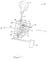
- a steering system 20 of a vehicle is shown generally.
- the steering system comprises a hand wheel 16 in operable communication with road wheels 18 (only one illustrated) of the vehicle through a steering column 15.
- Steering column 15 receives input from either hand wheel 16, which is in operable communication with a shaft 22, or a motor 70, which is in operable communication with a worm shaft 90 and a worm gear 60.
- a steering ratio adjuster 17 selects the appropriate ratio to adjust road wheels 18.
- a steering ratio adjuster 17 may be a linear differential gear system 11 and may be incorporated into steering column 15.
- the driver turns hand wheel 16, which turns shaft 22 at a 1:1 ratio to an output shaft 158, ultimately steering the road wheels 18 of the vehicle.
- motor 70 activates pursuant to a command from a controller (not shown) receiving and processing sensory information about an angle of road wheels 18, which occurs when road wheels 18 assume a position that is not desirable.
- motor 70 activates, it rotates a linear differential gear system 11, which is part of steering column 15.
- Linear differential gear system 11 rotates an output shaft 158 at a different speed from shaft 22. This rotation repositions road wheels 18 to achieve a more desirable handling and ride condition.
- a more detailed explanation of the operation is set forth herein under the "Operation" section.
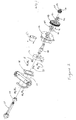
- a column head (shown on Figure 1 as 21) is connected to a shaft 22, which is in operable communication with an input shaft 38, preferably by a coupling 24.
- An input gear 48 is in operable communication with input shaft 38 and supported by bearings 42, 50.
- the operable communication is accomplished by a key 41 and key ways (not shown) disposed at input gear 48 and input shaft 38.
- the key/key way system prevents relative rotation between input gear 48 and input shaft 38.
- a retaining ring 52 secures both bearing 50 and input gear 48.
- Input gear 48 is meshed with a differential input gear 54.
- Differential input gear 54 is in operable communication with a differential input shaft 112.
- the operable communication is accomplished by a key 109 and key ways (one not shown), 55 disposed at differential input shaft 112 and differential input gear 54.
- the key/key way system prevents relative rotation between differential input gear 54 and differential input shaft 112.
- Differential input gear 54 is also axially supported along differential input shaft 112 by a retaining ring 56.
- Differential input shaft 112 is supported by bearings 44, 110.
- a sensor 59 Adjacent to differential input gear 54, a sensor 59 is plugged into a first end 57 of input shaft 112. Sensor 59 monitors the position of linear differential gear system 11.
- a worm gear 60 On the other side of differential input gear 54 is a worm gear 60, which is disposed at differential input shaft 112. Differential input shaft 112 passes through worm gear 60 and turns independently of worm gear 60.
- Worm gear 60 is rigidly connected to a differential carrier 127 so that differential carrier 127 rotates when worm gear 60 rotates.
- Differential carrier 127 comprises an input carrier plate 114 and an output carrier plate 126, which may be properly aligned by alignment pins 131.
- a pin 62 is disposed at worm gear 60 to stop worm gear 60 from rotating once worm gear 60 has turned a set distance. Pin 62 is more fully described in the operation section of this detailed description.
- a worm 92 is in operable communication with a worm shaft 90.
- the operable communication is accomplished by a key 88 and key ways 91, 93 disposed at worm 92 and worm shaft 90.
- the key/key way system prevents relative rotation between worm 92 and worm shaft 90.
- Worm 92 meshes with worm gear 60.
- Worm shaft 90 is supported by two bearings 66, 82.
- Bearing 66 is pressed against worm bearing thrust washer 96 and is axially supported to worm shaft 90 by a nut 68.
- Bearing 82 is pressed against worm bearing thrust washer 84 and is axially supported by a retaining ring 80.
- Belleville spring washers 86, 98 are disposed between worm bearing thrust washers 84, 96 and worm thrust washers 85, 94. Belleville spring washers 86, 98 prevent worm 92 from locking when worm gear 60 is prevented from rotating by pin 62.
- a motor 70 is in operable communication with worm shaft 90 so that motor 70 drives worm shaft 90. Preferably, the communication between motor 70 and worm shaft 90 is by a coupling 78. Motor 70 is mounted to a housing 64 by an adapter 76, which is secured by fasteners 72.
- bearing 110 adjacent to worm gear 60 is bearing 110, which is axially supported by a retaining ring 108.
- a retaining ring 107 supports bearing 110 and differential input shaft 112.
- Fixed at the end of differential input shaft 112 is an input sun gear 111.
- Differential input gear 54, input sun gear 111, and differential input shaft 112 rotate at the same speed.
- Input sun gear 111 meshes with preferably two input differential planet gears 115, 117. Input differential planet gears 115, 117 mesh with two output differential planet gears 118, 119. Input differential planet gears 115, 117 and output differential planet gears 118, 119 are connected to both input carrier plate 114 and output carrier plate 126 in a manner that allows rotation. Preferably, that connection is accomplished by mounting input differential planet gears 115, 117 and output differential planet gears 118, 119 on a pin 122. Also mounted on pin 122 are bushings 120, 121. Bushing 121 is pressed against input carrier plate 114. Bushing 120 is pressed against output carrier plate 126.
- output differential planet gears 118, 119 mesh with an output sun gear 123, which is fixed at the end of a differential output shaft 124.
- Differential output shaft 124 is supported by a bearing 134.
- Bearing 162 is assembled into output cover 164 and supports shaft 146.
- Bearing 134 is supported at differential output shaft 124 by retaining rings 132, 140.
- Input carrier plate 114 and output carrier plate 126 are mounted together by a fastener 142 and are supported by bearings 106, 128.
- Retaining rings 138, 144 also support differential carrier 127.
- a differential output gear 136 is disposed outside of differential carrier 127 and is in operable communication with differential output shaft 124.
- the operable communication is accomplished by a key 130 and key ways 129, (one not shown) disposed at differential output shaft 124 and differential output gear 136.
- the key/key way system prevents relative rotation between differential output gear 136 and differential output shaft 124.
- Differential output gear 136, output sun gear 123, and differential output shaft 124 rotate at the same speed.
- Differential output gear 136 meshes with an idler gear 152.
- Idler gear 152 is disposed at an idler shoulder bolt 146, secured by a retaining ring 150 and supported by a bearing 148. Shoulder bolt 146 is threaded into output cover 164.
- Idler gear 152 meshes with an output gear 154.
- Output gear 154 is in operable communication with an output shaft 158. Preferably, the operable communication is accomplished by a key 156 and key ways 161, 159 disposed at output shaft 158 and output gear 154. The key/key way system prevents relative rotation between output gear 154 and output shaft 158.
- a retaining ring 150 supports output gear 154 at output shaft 158.
- a bearing 160 supports output shaft 158 and is assembled into output cover 164.
- steering column 15 is contained in a housing 64, which preferably includes an input cover 45, an output cover 164, and a worm cover 100.
- Worm cover 100 is secured to housing 64 by fasteners 101.
- Input cover 45 is secured to housing 64 by fasteners 31.
- Output cover 164 is secured to housing 64 by fasteners 163.
- Input shaft 38 and output shaft 158 extend from housing 64.
- a bearing 166 supports output shaft 158 at output cover 164 and is secured by a retaining ring 168.
- Housing 64 is mounted to a bracket/jacket assembly 30 and secured by fasteners 25. Bracket/jacket assembly 30 mounts to column head (not shown).
- a position sensor 36 is mounted on input shaft 38 at the outside of housing 64 and adjacent to input housing cover 45.
- Another position sensor 170 is mounted at output shaft 158, outside of housing 64, and adjacent to output cover 164.
- Output shaft 158 is in operable communication with an intermediate shaft 182 by a universal joint 180.
- steering column 15 comprises a linear differential gear system 11, which operates with or without motor 70 being powered.
- steering system 20 operates in the following manner.
- the driver turns hand wheel 16, which is in operable communication with shaft 22 and input shaft 38. While the driver may turn hand wheel 16 either clockwise or counterclockwise, for purposes of illustration, assume that the driver has turned hand wheel 16 clockwise.
- the rotational force of hand wheel 16 is transmitted to input shaft 38, which rotates input gear 48 clockwise.
- Input gear 48 which is meshed with differential input gear 54, rotates differential input gear 54 counterclockwise.
- the torque ratio steps up 1:3 from input gear 48 to differential input gear 54.
- Differential input gear 54 rotates differential input shaft 112, which in turn rotates input sun gear 111 counterclockwise.
- Worm gear 60 is disposed at differential input shaft 112 between differential input gear 54 and input sun gear 111; however, differential input shaft 112 rotates independently from worm gear 60.
- Worm gear 60 is not directly rotated by hand wheel 16.
- Input sun gear 111 which meshes with two input differential planet gears 115, 117, rotates input differential planet gears 115, 117 clockwise.
- Two input differential planet gears 115, 117 mesh with two output differential planet gears 118, 119 and rotate output differential planet gears 118, 119 counterclockwise.
- Output differential planet gears 118, 119 mesh with output sun gear 123 and rotate output sun gear 123 clockwise.
- Output sun gear 123 rotates differential output shaft 124. All rotation from differential input gear 54 to output sun gear 123 occurs at a 1:1 ratio.
- differential output gear 136 Disposed at differential output shaft 124 at the opposite end from output sun gear 123 is differential output gear 136. Differential output gear 136 rotates in the same direction as output sun gear 123. Differential output gear 136 meshes with idler gear 152, which rotates counterclockwise. Idler gear 152 meshes with output gear 154, which rotates clockwise. Idler gear 152 is utilized to change the rotational direction of output shaft 158 without redesigning the linear differential. The torque is stepped back down by a 3:1 ratio from differential output gear 136 to output gear 154. The 1:3 ratio is used to enable the employment of smaller diameter gears in the linear differential gear system. By doing so, the overall dimension of the linear differential gear system are minimized. Moreover, the 1:3 ratio allows employment of a motor having a lower torque output. When output gear 154 turns clockwise, it rotates intermediate shaft 182 clockwise, which ultimately steers road wheels 18 to the right (passenger side) of the vehicle.
- Linear differential gear system 11 operates when motor 70 is powered. In that situation, the driver has either oversteered or understeered the vehicle and a controller (not shown) senses an inconsistency in the velocity, yaw, and direction of the vehicle. At the point that the driver has either oversteered or understeered the vehicle, controller (not shown) sends a signal to electric motor 70 to turn on.
- Output differential planet gears 118, 119 mesh with output sun gear 123 rotating output sun gear 123 counterclockwise.
- Output sun gear 123 rotates differential output shaft 124.
- differential output shaft 124 rotates, it turns differential output gear 136, which rotates in the same direction as output sun gear 123.
- the differential output gear 136 meshes with idler gear 152, which rotates clockwise.
- Idler gear 152 meshes with output gear 154, which rotates counterclockwise.
- Output gear 154 turns counterclockwise, it rotates intermediate shaft 182 counterclockwise, which ultimately steers road wheels 18 to the left (driver's side) of the vehicle.
- linear differential gear system 11 operates to slow down the steering output.
- the rotation of road wheels 18 can vary as to the input of the rotation of hand wheel 16 from ratios ranging from 1:1 up to 1:20.
- Motor 70 only operates long enough to adjust road wheels 18 enough to reposition road wheels 18 to a more desirable setting.
- road wheels 18 can only adjust a maximum of plus or minus five degrees as compared to the angle commanded by the driver.
- a pin 62 is located at worm gear 60 to stop worm gear 60 from rotating once it has steered road wheels 18 plus or minus five degrees. It will be appreciated that in an alternate embodiment, if worm gear 60 did not have pin 62 so located, then worm gear 60 could continue to turn, which would continue to turn road wheels 18 in a direction consistent with worm rotation direction.
Landscapes
- Engineering & Computer Science (AREA)
- Chemical & Material Sciences (AREA)
- Combustion & Propulsion (AREA)
- Transportation (AREA)
- Mechanical Engineering (AREA)
- Retarders (AREA)
- Power Steering Mechanism (AREA)
- Steering Control In Accordance With Driving Conditions (AREA)
Applications Claiming Priority (2)
| Application Number | Priority Date | Filing Date | Title |
|---|---|---|---|
| US19311300P | 2000-03-30 | 2000-03-30 | |
| US193113P | 2000-03-30 |
Publications (3)
| Publication Number | Publication Date |
|---|---|
| EP1138576A2 true EP1138576A2 (fr) | 2001-10-04 |
| EP1138576A3 EP1138576A3 (fr) | 2004-03-24 |
| EP1138576B1 EP1138576B1 (fr) | 2006-03-22 |
Family
ID=22712323
Family Applications (1)
| Application Number | Title | Priority Date | Filing Date |
|---|---|---|---|
| EP01201045A Expired - Lifetime EP1138576B1 (fr) | 2000-03-30 | 2001-03-21 | Commande assistée de direction avec engrenage différentiel linéaire |
Country Status (4)
| Country | Link |
|---|---|
| US (1) | US6575265B2 (fr) |
| EP (1) | EP1138576B1 (fr) |
| DE (1) | DE60118090T2 (fr) |
| ES (1) | ES2256152T3 (fr) |
Cited By (2)
| Publication number | Priority date | Publication date | Assignee | Title |
|---|---|---|---|---|
| EP1449744A3 (fr) * | 2003-02-21 | 2005-02-02 | Bayerische Motoren Werke Aktiengesellschaft, Patentabteilung AJ-3 | Superposition de direction pour un véhicule à moteur |
| EP1700772A3 (fr) * | 2005-03-09 | 2006-12-13 | Jtekt Corporation | Appareil de transmission de rotation |
Families Citing this family (25)
| Publication number | Priority date | Publication date | Assignee | Title |
|---|---|---|---|---|
| US6942057B2 (en) * | 2001-11-21 | 2005-09-13 | Delphi Technologies, Inc. | Feel control for active steering |
| JP2003312515A (ja) * | 2002-04-24 | 2003-11-06 | Koyo Seiko Co Ltd | 車両用操舵装置 |
| US6926114B2 (en) * | 2002-06-03 | 2005-08-09 | Delphi Technologies, Inc. | Assist modification in active front steering |
| KR100494515B1 (ko) * | 2003-05-21 | 2005-06-10 | 현대자동차주식회사 | 자동 변속기의 유성기어용 캐리어 |
| US7063636B2 (en) * | 2003-06-16 | 2006-06-20 | Delphi Technologies, Inc. | Mechanically linked active steering system |
| US20070175695A1 (en) * | 2003-09-22 | 2007-08-02 | Dishop Steering Technology Limited | Steering gear |
| US20070029748A1 (en) * | 2003-10-14 | 2007-02-08 | Bishop Innovation Limited | Steering system |
| DE10353084A1 (de) * | 2003-11-13 | 2005-06-23 | Bayerische Motoren Werke Ag | Hilfskraftunterstütztes Lenksystem eines Kraftfahrzeugs |
| EP1682399B1 (fr) * | 2003-11-13 | 2007-08-29 | Bayerische Motoren Werke Aktiengesellschaft | Systeme de direction assistee d'un vehicule automobile |
| DE10353083B4 (de) * | 2003-11-13 | 2015-06-11 | Bayerische Motoren Werke Aktiengesellschaft | Hilfskraftunterstütztes Lenksystem eines Kraftfahrzeugs |
| JP2006015856A (ja) * | 2004-07-01 | 2006-01-19 | Toyoda Mach Works Ltd | 伝達比可変操舵装置 |
| US7322898B2 (en) | 2004-09-03 | 2008-01-29 | Delphi Technologies, Inc. | Active front steering actuator |
| US7530422B2 (en) * | 2004-09-17 | 2009-05-12 | Delphi Technologies, Inc. | Force and position control for active front steering |
| US7240760B2 (en) * | 2005-07-25 | 2007-07-10 | Trw Automotive U.S. Llc | Steering apparatus |
| US7890239B2 (en) * | 2005-10-13 | 2011-02-15 | Toyota Jidosha Kabushiki Kaisha | Vehicle suppressing OS or US by stagedly different devices |
| DE102006003654A1 (de) * | 2006-01-26 | 2007-10-11 | Zf Lenksysteme Gmbh | Lenkwelle für ein Lenkrad mit feststehender Lenknabe und Hilfskraftquelle |
| DE102006031290A1 (de) * | 2006-02-06 | 2007-08-09 | Zf Lenksysteme Gmbh | Lenkwelle für ein Lenkrad mit feststehender Lenknabe und einem Überlagerungsgetriebe |
| JP2008087672A (ja) * | 2006-10-03 | 2008-04-17 | Jtekt Corp | 車両用操舵装置 |
| JP5013193B2 (ja) * | 2007-10-22 | 2012-08-29 | 株式会社ジェイテクト | 車両用操舵装置 |
| CN101654116B (zh) * | 2008-08-19 | 2011-12-14 | 上海通用汽车有限公司 | 一种用于汽车转向器传动比调试的行星齿轮机构 |
| FR2954904B1 (fr) * | 2010-01-04 | 2011-12-16 | Obl | Distracteur mandibulaire intraoral sur mesure et utilisation d'un tel distracteur afin d'obtenir une distraction en continu |
| CN104843053B (zh) * | 2014-07-04 | 2018-03-27 | 北汽福田汽车股份有限公司 | 汽车转向系统的转向器、汽车转向系统以及汽车 |
| CN106515841B (zh) * | 2016-11-02 | 2018-06-08 | 常州工学院 | 一种可变传动比转向系统的控制机构 |
| CN107226128B (zh) * | 2017-05-15 | 2019-03-05 | 长安大学 | 基于双电机行星齿轮结构的电动助力转向系统及方法 |
| TWM582093U (zh) * | 2019-03-28 | 2019-08-11 | 益航電子股份有限公司 | Gearbox with motor fixed structure |
Family Cites Families (16)
| Publication number | Priority date | Publication date | Assignee | Title |
|---|---|---|---|---|
| FR2570786B1 (fr) * | 1984-09-26 | 1989-02-24 | Pochard Camille | Variateur de vitesse automatique a reflexes dynamometriques |
| US4658927A (en) * | 1984-11-19 | 1987-04-21 | Mazda Motor Corporation | Steering system for vehicle |
| JPS61166772A (ja) * | 1985-01-21 | 1986-07-28 | Nissan Motor Co Ltd | 車両用操舵装置 |
| US4739855A (en) * | 1985-07-22 | 1988-04-26 | Mazda Motor Corporation | Vehicle steering system having a steering ratio changing mechanism |
| FR2622857B1 (fr) * | 1987-11-10 | 1990-03-09 | Renault | Mecanisme de direction a demultiplication variable asservi a la vitesse du vehicule |
| US4956590A (en) * | 1988-10-06 | 1990-09-11 | Techco Corporation | Vehicular power steering system |
| JPH084383Y2 (ja) * | 1989-10-02 | 1996-02-07 | トヨタ自動車株式会社 | 車両用操蛇装置 |
| JP2809847B2 (ja) * | 1990-09-06 | 1998-10-15 | 本田技研工業株式会社 | 可変舵角比操舵装置 |
| GB2261860B (en) * | 1991-10-30 | 1995-08-09 | Honda Motor Co Ltd | Steering apparatus with variable steering angle ratio for pitman arm steering mechanism |
| JPH0656048A (ja) * | 1992-08-05 | 1994-03-01 | Honda Motor Co Ltd | 可変舵角比操舵装置 |
| US5762162A (en) * | 1995-12-22 | 1998-06-09 | General Motors Corporation | Electric power steering apparatus |
| US5933784A (en) * | 1996-06-28 | 1999-08-03 | Synacom Technology, Inc. | Signaling gateway system and method |
| US5884157A (en) * | 1996-08-02 | 1999-03-16 | Qualcomm Incorporated | Method and apparatus for supporting multiple service providers using single mobile switching center |
| JP3531712B2 (ja) * | 1997-06-04 | 2004-05-31 | トヨタ自動車株式会社 | 車両用操舵装置 |
| US6148204A (en) * | 1997-09-12 | 2000-11-14 | Motorola, Inc. | Method and apparatus for a distributed location register |
| JPH11334627A (ja) * | 1998-05-28 | 1999-12-07 | Toyota Motor Corp | 車両用操舵制御装置 |
-
2001
- 2001-03-19 US US09/812,240 patent/US6575265B2/en not_active Expired - Fee Related
- 2001-03-21 DE DE60118090T patent/DE60118090T2/de not_active Expired - Fee Related
- 2001-03-21 ES ES01201045T patent/ES2256152T3/es not_active Expired - Lifetime
- 2001-03-21 EP EP01201045A patent/EP1138576B1/fr not_active Expired - Lifetime
Cited By (3)
| Publication number | Priority date | Publication date | Assignee | Title |
|---|---|---|---|---|
| EP1449744A3 (fr) * | 2003-02-21 | 2005-02-02 | Bayerische Motoren Werke Aktiengesellschaft, Patentabteilung AJ-3 | Superposition de direction pour un véhicule à moteur |
| EP1700772A3 (fr) * | 2005-03-09 | 2006-12-13 | Jtekt Corporation | Appareil de transmission de rotation |
| US7678004B2 (en) | 2005-03-09 | 2010-03-16 | Jtekt Corporation | Steering apparatus |
Also Published As
| Publication number | Publication date |
|---|---|
| ES2256152T3 (es) | 2006-07-16 |
| EP1138576A3 (fr) | 2004-03-24 |
| US6575265B2 (en) | 2003-06-10 |
| EP1138576B1 (fr) | 2006-03-22 |
| DE60118090T2 (de) | 2006-08-24 |
| DE60118090D1 (de) | 2006-05-11 |
| US20020029922A1 (en) | 2002-03-14 |
Similar Documents
| Publication | Publication Date | Title |
|---|---|---|
| US6575265B2 (en) | Linear differential assisted controlled steering | |
| US6000491A (en) | Electric power steering apparatus having steering torque sensor integrally assembled in steering device with variable steering ratio | |
| US5002142A (en) | Vehicle steering system | |
| US5735363A (en) | Auxiliary drive apparatus | |
| EP3934963B1 (fr) | Appareil destiné à être utilisé pour tourner des roues de véhicule orientables | |
| GB2211156A (en) | Power steering apparatus | |
| JP2567397B2 (ja) | 車輪操舵装置 | |
| US5878832A (en) | Steering apparatus for motor vehicle | |
| US4987963A (en) | Steering gear for the roadwheels of a vehicle | |
| US6076628A (en) | Power assist apparatus for motor vehicle steering | |
| US5050697A (en) | Steering apparatus for automotive vehicle | |
| EP1342643B1 (fr) | Actionneurs de direction | |
| US5161813A (en) | Vehicle steering apparatus and a vehicle provided with the same | |
| US20240034392A1 (en) | Vehicle steering apparatus | |
| JP2005247214A (ja) | 電動パワーステアリング装置 | |
| KR20210059814A (ko) | 자동차용 모듈형 스티어링 장치 | |
| CN112013091B (zh) | 用于车辆动力转向组件的球式螺母组件的支承件 | |
| CN100422024C (zh) | 用于车辆的叠加转向系统 | |
| CN117681951A (zh) | 限位装置、线控转向系统和车辆 | |
| JPH07237551A (ja) | 電動式パワーステアリング装置 | |
| EP0688281A1 (fr) | Appareil d'entrainement auxiliaire | |
| JP2005324708A (ja) | 電動パワーステアリング装置 | |
| JPH058740A (ja) | 電動式四輪操舵装置 | |
| EP0967133A2 (fr) | Dispositif de fixation d'une unité de commande électronique pour un système d'assistance électrique de direction | |
| JP2000118422A (ja) | 電動式パワーステアリング装置 |
Legal Events
| Date | Code | Title | Description |
|---|---|---|---|
| PUAI | Public reference made under article 153(3) epc to a published international application that has entered the european phase |
Free format text: ORIGINAL CODE: 0009012 |
|
| AK | Designated contracting states |
Kind code of ref document: A2 Designated state(s): AT BE CH CY DE DK ES FI FR GB GR IE IT LI LU MC NL PT SE TR |
|
| AX | Request for extension of the european patent |
Free format text: AL;LT;LV;MK;RO;SI |
|
| PUAL | Search report despatched |
Free format text: ORIGINAL CODE: 0009013 |
|
| AK | Designated contracting states |
Kind code of ref document: A3 Designated state(s): AT BE CH CY DE DK ES FI FR GB GR IE IT LI LU MC NL PT SE TR |
|
| AX | Request for extension of the european patent |
Extension state: AL LT LV MK RO SI |
|
| 17P | Request for examination filed |
Effective date: 20040924 |
|
| AKX | Designation fees paid |
Designated state(s): DE ES FR GB IT |
|
| 17Q | First examination report despatched |
Effective date: 20041229 |
|
| GRAP | Despatch of communication of intention to grant a patent |
Free format text: ORIGINAL CODE: EPIDOSNIGR1 |
|
| GRAS | Grant fee paid |
Free format text: ORIGINAL CODE: EPIDOSNIGR3 |
|
| GRAA | (expected) grant |
Free format text: ORIGINAL CODE: 0009210 |
|
| AK | Designated contracting states |
Kind code of ref document: B1 Designated state(s): DE ES FR GB IT |
|
| REG | Reference to a national code |
Ref country code: GB Ref legal event code: FG4D |
|
| REF | Corresponds to: |
Ref document number: 60118090 Country of ref document: DE Date of ref document: 20060511 Kind code of ref document: P |
|
| REG | Reference to a national code |
Ref country code: ES Ref legal event code: FG2A Ref document number: 2256152 Country of ref document: ES Kind code of ref document: T3 |
|
| ET | Fr: translation filed | ||
| PLBE | No opposition filed within time limit |
Free format text: ORIGINAL CODE: 0009261 |
|
| STAA | Information on the status of an ep patent application or granted ep patent |
Free format text: STATUS: NO OPPOSITION FILED WITHIN TIME LIMIT |
|
| 26N | No opposition filed |
Effective date: 20061227 |
|
| PGFP | Annual fee paid to national office [announced via postgrant information from national office to epo] |
Ref country code: GB Payment date: 20070321 Year of fee payment: 7 |
|
| PGFP | Annual fee paid to national office [announced via postgrant information from national office to epo] |
Ref country code: ES Payment date: 20070417 Year of fee payment: 7 |
|
| PGFP | Annual fee paid to national office [announced via postgrant information from national office to epo] |
Ref country code: IT Payment date: 20080322 Year of fee payment: 8 |
|
| PGFP | Annual fee paid to national office [announced via postgrant information from national office to epo] |
Ref country code: DE Payment date: 20080313 Year of fee payment: 8 Ref country code: FR Payment date: 20080311 Year of fee payment: 8 |
|
| GBPC | Gb: european patent ceased through non-payment of renewal fee |
Effective date: 20080321 |
|
| REG | Reference to a national code |
Ref country code: ES Ref legal event code: FD2A Effective date: 20080322 |
|
| PG25 | Lapsed in a contracting state [announced via postgrant information from national office to epo] |
Ref country code: GB Free format text: LAPSE BECAUSE OF NON-PAYMENT OF DUE FEES Effective date: 20080321 |
|
| PG25 | Lapsed in a contracting state [announced via postgrant information from national office to epo] |
Ref country code: ES Free format text: LAPSE BECAUSE OF NON-PAYMENT OF DUE FEES Effective date: 20080322 |
|
| REG | Reference to a national code |
Ref country code: FR Ref legal event code: ST Effective date: 20091130 |
|
| PG25 | Lapsed in a contracting state [announced via postgrant information from national office to epo] |
Ref country code: DE Free format text: LAPSE BECAUSE OF NON-PAYMENT OF DUE FEES Effective date: 20091001 |
|
| PG25 | Lapsed in a contracting state [announced via postgrant information from national office to epo] |
Ref country code: FR Free format text: LAPSE BECAUSE OF NON-PAYMENT OF DUE FEES Effective date: 20091123 |
|
| PG25 | Lapsed in a contracting state [announced via postgrant information from national office to epo] |
Ref country code: IT Free format text: LAPSE BECAUSE OF NON-PAYMENT OF DUE FEES Effective date: 20090321 |