EP1138998A2 - Tuyau composite imperméable aux fluides - Google Patents
Tuyau composite imperméable aux fluides Download PDFInfo
- Publication number
- EP1138998A2 EP1138998A2 EP01106945A EP01106945A EP1138998A2 EP 1138998 A2 EP1138998 A2 EP 1138998A2 EP 01106945 A EP01106945 A EP 01106945A EP 01106945 A EP01106945 A EP 01106945A EP 1138998 A2 EP1138998 A2 EP 1138998A2
- Authority
- EP
- European Patent Office
- Prior art keywords
- layer
- hose
- fluid
- laminated
- resin
- Prior art date
- Legal status (The legal status is an assumption and is not a legal conclusion. Google has not performed a legal analysis and makes no representation as to the accuracy of the status listed.)
- Withdrawn
Links
Images
Classifications
-
- F—MECHANICAL ENGINEERING; LIGHTING; HEATING; WEAPONS; BLASTING
- F16—ENGINEERING ELEMENTS AND UNITS; GENERAL MEASURES FOR PRODUCING AND MAINTAINING EFFECTIVE FUNCTIONING OF MACHINES OR INSTALLATIONS; THERMAL INSULATION IN GENERAL
- F16L—PIPES; JOINTS OR FITTINGS FOR PIPES; SUPPORTS FOR PIPES, CABLES OR PROTECTIVE TUBING; MEANS FOR THERMAL INSULATION IN GENERAL
- F16L11/00—Hoses, i.e. flexible pipes
-
- F—MECHANICAL ENGINEERING; LIGHTING; HEATING; WEAPONS; BLASTING
- F16—ENGINEERING ELEMENTS AND UNITS; GENERAL MEASURES FOR PRODUCING AND MAINTAINING EFFECTIVE FUNCTIONING OF MACHINES OR INSTALLATIONS; THERMAL INSULATION IN GENERAL
- F16L—PIPES; JOINTS OR FITTINGS FOR PIPES; SUPPORTS FOR PIPES, CABLES OR PROTECTIVE TUBING; MEANS FOR THERMAL INSULATION IN GENERAL
- F16L11/00—Hoses, i.e. flexible pipes
- F16L11/04—Hoses, i.e. flexible pipes made of rubber or flexible plastics
- F16L11/12—Hoses, i.e. flexible pipes made of rubber or flexible plastics with arrangements for particular purposes, e.g. specially profiled, with protecting layer, heated, electrically conducting
-
- F—MECHANICAL ENGINEERING; LIGHTING; HEATING; WEAPONS; BLASTING
- F16—ENGINEERING ELEMENTS AND UNITS; GENERAL MEASURES FOR PRODUCING AND MAINTAINING EFFECTIVE FUNCTIONING OF MACHINES OR INSTALLATIONS; THERMAL INSULATION IN GENERAL
- F16L—PIPES; JOINTS OR FITTINGS FOR PIPES; SUPPORTS FOR PIPES, CABLES OR PROTECTIVE TUBING; MEANS FOR THERMAL INSULATION IN GENERAL
- F16L11/00—Hoses, i.e. flexible pipes
- F16L11/04—Hoses, i.e. flexible pipes made of rubber or flexible plastics
- F16L2011/047—Hoses, i.e. flexible pipes made of rubber or flexible plastics with a diffusion barrier layer
-
- Y—GENERAL TAGGING OF NEW TECHNOLOGICAL DEVELOPMENTS; GENERAL TAGGING OF CROSS-SECTIONAL TECHNOLOGIES SPANNING OVER SEVERAL SECTIONS OF THE IPC; TECHNICAL SUBJECTS COVERED BY FORMER USPC CROSS-REFERENCE ART COLLECTIONS [XRACs] AND DIGESTS
- Y10—TECHNICAL SUBJECTS COVERED BY FORMER USPC
- Y10S—TECHNICAL SUBJECTS COVERED BY FORMER USPC CROSS-REFERENCE ART COLLECTIONS [XRACs] AND DIGESTS
- Y10S138/00—Pipes and tubular conduits
- Y10S138/10—Metal foil
Definitions
- This invention relates to a fluid-impermeable composite hose. More particularly, it relates to a fluid-impermeable composite hose having a fluid-impermeable layer formed by sandwiching between two thin resin layers a laminated layer containing a metallic foil, or a metallic layer formed by vapor deposition.
- the hose of this invention is particularly suitable for use on a motor vehicle as a hose for transporting a refrigerant, such as carbon dioxide, or as a fuel hose.
- every hose used for transporting a refrigerant, such as carbon dioxide, in an air-conditioning system on a motor vehicle be impermeable to the refrigerant.
- a refrigerant such as carbon dioxide
- One of the most effective approaches lies in a hose having a laminated wall layer which contains a metallic foil, or a metallic layer formed by vapor deposition.
- Environmental protection also requires a fuel hose to be impermeable to fuel, and a laminated wall layer is very useful for a fuel hose, too.
- the laminated layer employed as described is, however, not thoroughly secured or reinforced in the wall of the hose. Therefore, it is directly affected by any bending, deforming or stretching force acting upon the wall of the hose as a result of e.g. an elevation in pressure of the refrigerant in the hose, the vibration of the vehicle, or any impact bearing upon it.
- the metallic foil or layer in the laminated layer is easily broken and the hose loses its fluid impermeability.
- an object of this invention to prevent effectively any breakage of a metallic foil or layer in a laminated layer of a fluid-impermeable composite hose.
- the inventors of this invention have thought that it is very effective to sandwich a laminated layer between two thin resin layers, and that the hose is flexible enough if those resin layers are adequate.
- a hose having a wall comprising a fluid-impermeable layer of a sandwiched structure in which a laminated layer is held between two thin resin layers, the laminated layer containing a metallic foil, or a metallic layer formed by vapor deposition.
- the laminated layer is secured and protected by the two thin resin layers located radially inwardly and outwardly thereof.
- the bending, deforming or stretching force acting upon the hose for various reasons is absorbed or diminished by those resin layers, and is not directly transmitted to the laminated layer. No force acts upon the metallic foil or layer in the laminated layer to twist, bend, stretch or otherwise deform it.
- the metallic foil or layer is not easily broken, and the hose does not lose its fluid impermeability.
- the fluid-impermeable layer forms the innermost layer of the wall of the hose.
- the thin resin layer on the inside of the fluid-impermeable layer is superior to any rubber layer in refrigerant impermeability. Unlike a rubber layer, it does not deteriorate by swelling or foaming even when carbon dioxide as a refrigerant is in its supercritical state at a high temperature and a high pressure.
- the hose is particularly suitable as a hose for transporting carbon dioxide as a refrigerant for e.g. an air conditioner on a motor vehicle.
- the wall has a rubber layer inwardly of the fluid-impermeable layer.
- a rubber layer inwardly of the fluid-impermeable layer.
- Such a layer can be of a material having a high resistance to swelling with fuel and a high impermeability to fuel, such as fluororubber (FKM) or acrylonitrile-butadiene rubber (NBR), so that the hose may be suitable as a fuel hose.
- FKM fluororubber
- NBR acrylonitrile-butadiene rubber
- the wall has a reinforcing layer and an outer rubber layer outwardly of the fluid-impermeable layer.
- the reinforcing layer gives pressure resistance and strength to the hose.
- the outer rubber layer gives ozone resistance to the hose, protects it from any external impact, and improves the tightness of a seal in a joint between the hose and a pipe.
- the wall has an intermediate rubber layer interposed between the fluid-impermeable layer and the reinforcing layer.
- the intermediate rubber layer gives an improved adhesion between the fluid-impermeable layer and the reinforcing layer, diminishes any bending, deforming or stretching force acting upon the fluid-impermeable layer, and improves the flexibility of the hose as a whole.
- the laminated layer is formed by spirally winding or longitudinally lapping a tape of a laminated sheet containing one of the following (1) to (3) and a resin film or films laminated thereon:
- At least one of the thin resin layers on the inside and outside of the fluid-impermeable layer is of an ethylene-vinyl alcohol copolymer resin (EVOH), a blend of a polyamide and a modified polyolefin resin, a polyamide resin, or a fluororesin. All of these resins are high in fluid impermeability for refrigerant or fuel and in flexibility, so that the hose has a still higher fluid impermeability, and is flexible enough to withstand the vibration of a motor vehicle, or its engine.
- EVOH ethylene-vinyl alcohol copolymer resin
- All of these resins are high in fluid impermeability for refrigerant or fuel and in flexibility, so that the hose has a still higher fluid impermeability, and is flexible enough to withstand the vibration of a motor vehicle, or its engine.
- At least one of the thin resin layers on the inside and outside of the fluid-impermeable layer has a thickness of 20 to 300 ⁇ m. This is a preferred range in which the resin layers can perform its protective action effectively and thus ensure the fluid impermeability without affecting the flexibility of the hose in any way.
- the fluid-impermeable composite hose of this invention can be used for transporting various kinds of fluids. Its preferred use is, however, for transporting a refrigerant, or fuel, particularly in a motor vehicle.
- the fluid-impermeable composite hose according to the second aspect is preferred, and the fluid-impermeable composite hose according to the third aspect is preferred as the fuel hose.
- the hose of this invention comprises in its wall a fluid-impermeable layer formed by sandwiching a laminated layer containing a metallic foil or a metallic layer formed by vapor deposition, between two thin resin layers. It may or may not have another layer or layers.
- the laminated layer may be employed in any position relative to the remaining layer or layers and may, for example, be employed as an inner or intermediate layer.
- the fluid-impermeable layer may form the innermost layer of the wall, or may be lined with a rubber layer.
- the latter may be of any rubber, but is preferably of e.g. FKM or NBR if the hose is a fuel hose.
- the fluid-impermeable layer may be surrounded by another layer, or layers.
- it may be surrounded by a reinforcing layer and an outer rubber layer, and an intermediate rubber layer may be interposed between the fluid-impermeable layer and the reinforcing layer.
- the laminated layer and the inner and outer thin resin layers which form the fluid-impermeable layer are preferably bonded to one another. However, they may not be bonded.
- a usually appropriate process for making the fluid-impermeable layer may include forming the inner resin layer by extrusion, forming the laminated layer about it and forming the outer resin layer by extrusion, though other appropriate processes may be used.
- the laminated layer may be of any construction if it is a laminate containing a metallic foil or a metallic layer formed by vapor deposition. However, it is preferably composed of (1) a metallic foil, (2) a metallic foil with a reinforcing material, or (3) a metallic layer formed by vapor deposition; and a resin film or films laminated thereon.
- the laminated layer is preferably formed by spirally winding or longitudinally lapping a tape of a laminated sheet composed of one of the (1) to (3) above, and a resin film or films.
- Spiral winding is a method in which a tape of a laminated sheet is wound spirally to form a cylindrical layer having no gap between any two adjoining turns.
- Longitudinal lapping is a method in which a tape of a laminated sheet having a width large enough to encircle a hose to be made is placed in parallel to the longitudinal axis of the hose and bent into a cylindrical layer having no gap between two longitudinal edges thereof.
- the laminated sheet is usually made by placing the metallic foil or the metallic layer between two resin films and bonding the films to each other with an adhesive, or welding them to each other.
- a laminated sheet containing a metallic layer formed by vapor deposition may be made by forming such a layer on one side of a resin film and welding or otherwise bonding another resin film to that side.
- a laminated sheet may also be made by forming a metallic layer by vapor deposition on each of two resin films and welding or otherwise bonding the films to each other in such a way that the metallic layers may join each other.
- the reinforcing material is preferably bonded to the foil to produce a higher reinforcing effect.
- the reinforcing material is preferably situated radially outwardly of the foil.
- the foil and reinforcing material may or may not be bonded to the resin films. While any kind of reinforcing material may be used, preferred examples are a wire mesh and a reinforcing cloth because of their high stretch resistance and flexibility. Examples of the reinforcing cloths include a canvas and a nonwoven fabric, preferably made from aramid, carbon, glass or like fibers of low stretchability. A resin film of high strength can also be used as the reinforcing material.
- the resin films may be of any appropriate resin, such as a polyamide resin, a polyethylene-terephthalate resin or EVOH.
- Each film preferably has a thickness of, say, 5 to 100 ⁇ m. If its thickness is too large, the laminated sheet is difficult to apply by spiral winding or longitudinal lapping.
- the laminated sheet spirally wound or longitudinally lapped preferably has a pair of spirally or longitudinally extending edge portions overlapping each other to ensure high fluid impermeability. Its overlapping edge portions are preferably bonded to each other to ensure a still higher degree of fluid impermeability.
- any resinous material may be used for the thin resin layers between which the laminated layer is held to form the fluid-impermeable layer, since the resinous materials are generally more impermeable to a refrigerant or fuel than rubbers are. Moreover, the resinous materials are much less liable to deteriorate by swelling or foaming with carbon dioxide in its supercritical state.
- Preferred resinous materials include EVOH and a polyamide resin.
- Other preferred examples include a modified polyolefin resin obtained by graft polymerization of an unsaturated carboxylic acid or a derivative thereof to a polyolefin consisting basically of e.g. ethylene or propylene, and a mixture of any such modified polyolefin resin and a polyamide resin.
- EVOH is, among others, preferred, since it enables the fluid-impermeable layer to resist any undesirably large drop in fluid impermeability even if the metallic foil or layer may have been damaged or broken.
- polystyrene resins examples include nylon 6, nylon 66, nylon 11, nylon 12, or a copolymer thereof, and a polyamide resin having an aromatic, such as m-xylenediamine, in its principal chain.
- Other preferred resinous materials include polyethylene or polybutylene terephthalate, and polyethylene or polybutylene naphthalate.
- the resin layers can be formed by any known method, such as extrusion molding. They preferably have a thickness not exceeding 300 ⁇ m each, or not exceeding 500 ⁇ m in total, to ensure the flexibility of the hose. An extremely small layer thickness in the order of, say, less than 20 ⁇ m should, however, be avoided to ensure fluid impermeability and the formation of a resin layer of uniform thickness not having any opening therein.
- the resin layers are preferably bonded to the laminated layer by, for example, using an adhesive, or welding.
- An intermediate rubber layer may be interposed between the fluid-impermeable layer and a reinforcing layer surrounding it, if any, to ensure improved adhesion, protection and flexibility, as stated before.
- the intermediate rubber layer gives effects as mentioned above with respect to the fifth aspect of the invention. It is preferably of, for example, butyl rubber (IIR), halogenated butyl rubber, ethylene-propylene rubber, ethylene-propylene-diene rubber (EPDM), or nitrile rubber (NBR). These rubbers are high in fluid impermeability and flexibility, and easily achieve a good adhesion to the fluid-impermeable and reinforcing layers at a high temperature.
- the intermediate rubber layer preferably has a thickness of, say, 0.2 to 1.5 mm.
- the hose preferably has a reinforcing layer in its wall.
- the reinforcing layer may, for example, be a braided wire layer, or a layer formed by braiding reinforcing yarn, or winding reinforcing yarn in two spiral layers extending in the opposite directions, or placing an intermediate rubber layer between two such spiral layers.
- An outer rubber layer may form the outermost wall layer of the hose. It is preferably of any rubber of high weatherability, such as chloroprene rubber (CR), IIR, chlorosulfonated polyethylene rubber (CSM), or EPDM.
- CR chloroprene rubber
- IIR chloroprene rubber
- CSM chlorosulfonated polyethylene rubber
- EPDM EPDM
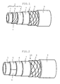
- a fluid-impermeable composite hose 1 sequentially comprises a fluid-impermeable layer 2 as the innermost layer of its wall, an intermediate rubber layer 7 formed from IIR, a reinforcing layer 8 formed by braiding an appropriate kind of reinforcing yarn, and an outer rubber layer 9 formed from IIR.
- the fluid-impermeable layer 2 is composed of an inner thin resin layer 3 formed by extrusion from EVOH and having a thickness of 150 ⁇ m, a laminated layer 5 formed by winding a tape of a laminated sheet 4 spirally, and an outer thin resin layer 6 formed by extrusion from EVOH and having a thickness of 150 ⁇ m.
- the outer thin resin layer 6 and the intermediate rubber layer 7 are appropriately bonded to each other by vulcanization, and so are the intermediate rubber layer 7 and the reinforcing layer 8.
- the laminated sheet 4 has a pair of spirally extending edge portions overlapping each other and bonded to each other.
- FIG. 2 shows a hose 10 according to another embodiment of this invention.
- Its fluid-impermeable layer is composed of an inner thin resin layer 3 formed from a polyamide resin, a laminated layer 5 formed by longitudinally lapping a tape of a laminated sheet 4 and having a pair of longitudinally extending edge portions overlapping each other and bonded to each other, and an outer thin resin layer 6 formed from a polyamide resin.
- the hose 10 is identical to the hose 1 shown in FIG. 1.
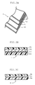
- the laminated sheet 4 used in the hoses shown in FIGS. 1 and 2 are shown in detail in FIGS. 3A and 3B. It includes an aluminum foil 4c as a metallic foil and a resin sheet as a reinforcing material 4d which are sandwiched between an inner resin layer 4a in the form of a thin film of a thermoplastic PET resin and a similar outer resin layer 4b, and bonded thereto.
- the metallic foil 4c is bonded to the reinforcing material 4d with an adhesive not shown, and is thereby so bound as not to be affected at all by any tensile or like force acting upon the laminated sheet 4.
- FIG. 3C shows a modified form of laminated sheet 4. It does not have any reinforcing material as shown at 4d in FIG. 3B., but has only a metallic foil 4c held between its inner and outer resin layers 4a and 4b.
Landscapes
- Engineering & Computer Science (AREA)
- General Engineering & Computer Science (AREA)
- Mechanical Engineering (AREA)
- Rigid Pipes And Flexible Pipes (AREA)
- Laminated Bodies (AREA)
Applications Claiming Priority (2)
| Application Number | Priority Date | Filing Date | Title |
|---|---|---|---|
| JP2000083214A JP2001263544A (ja) | 2000-03-21 | 2000-03-21 | 非透過型複合ホース |
| JP2000083214 | 2000-03-21 |
Publications (2)
| Publication Number | Publication Date |
|---|---|
| EP1138998A2 true EP1138998A2 (fr) | 2001-10-04 |
| EP1138998A3 EP1138998A3 (fr) | 2002-04-17 |
Family
ID=18599892
Family Applications (1)
| Application Number | Title | Priority Date | Filing Date |
|---|---|---|---|
| EP01106945A Withdrawn EP1138998A3 (fr) | 2000-03-21 | 2001-03-20 | Tuyau composite imperméable aux fluides |
Country Status (3)
| Country | Link |
|---|---|
| US (1) | US6345647B2 (fr) |
| EP (1) | EP1138998A3 (fr) |
| JP (1) | JP2001263544A (fr) |
Cited By (4)
| Publication number | Priority date | Publication date | Assignee | Title |
|---|---|---|---|---|
| EP1321702A1 (fr) * | 2001-12-20 | 2003-06-25 | Pipelife Nederland B.V. | Tuyau en matière plastique imperméable renforcé |
| EP1393889A1 (fr) * | 2002-08-28 | 2004-03-03 | The Goodyear Tire & Rubber Company | Tuyau pour fluide frigorigène |
| EP1418375A1 (fr) | 2002-11-05 | 2004-05-12 | Veritas Ag | Tuyau flexible multicouche |
| WO2007025381A1 (fr) * | 2005-09-01 | 2007-03-08 | Pratt & Whitney Canada Corp. | Barrière d’écoulement hydrostatique pour rampe souple de distribution de carburant |
Families Citing this family (28)
| Publication number | Priority date | Publication date | Assignee | Title |
|---|---|---|---|---|
| DE19837497A1 (de) | 1998-08-13 | 2000-02-24 | Trinova Aeroquip Gmbh | Flexibler strangförmiger Hohlkörper |
| DE19837498A1 (de) * | 1998-08-13 | 2000-02-24 | Trinova Aeroquip Gmbh | Flexibler strangförmiger Hohlkörper |
| US6945279B2 (en) * | 2000-09-29 | 2005-09-20 | Yamashita Rubber Kabushiki Kaisha | Thin-walled rubber hose and method of producing the same |
| US20030070720A1 (en) * | 2001-09-27 | 2003-04-17 | Kevin Bergevin | Barrier tubing |
| BR0301971A (pt) | 2002-06-06 | 2005-03-15 | Goodyear Tire & Rubber | Mangueira de célula de combustìvel com propriedades de barreira |
| EP1433990A1 (fr) * | 2002-12-26 | 2004-06-30 | Calsonic Kansei Corporation | Tuyau flexible |
| AU2004261313B2 (en) * | 2003-07-30 | 2011-01-27 | Sonoco Australia Pty Limited | Multi-layer tube of improved physical properties |
| AU2003903948A0 (en) | 2003-07-30 | 2003-08-14 | Ezytube Pty Limted | Multi-layer tube of improved tensile strength |
| ES2527663T3 (es) * | 2004-01-29 | 2015-01-28 | TI Automotive (Fuldabrück) GmbH | Tubo de material sintético de múltiples capas con propiedades de barrera |
| US20070134458A1 (en) * | 2004-02-06 | 2007-06-14 | Lovett Brad A | Aromatic polyamide tubing for vehicle applications |
| JP2005272786A (ja) * | 2004-03-26 | 2005-10-06 | Tokai Rubber Ind Ltd | 燃料改質システム用ゴム組成物およびそれを用いた燃料改質システム用ゴムホース |
| JP2005315406A (ja) * | 2004-03-31 | 2005-11-10 | Bridgestone Corp | 冷媒輸送用ホース |
| ITMI20040704A1 (it) * | 2004-04-08 | 2004-07-08 | Guala Closures Spa | Struttura di tubo ad elevata flessibilita' e resistenza termica e a bassa permeabilita' |
| JP4626230B2 (ja) * | 2004-09-02 | 2011-02-02 | 東海ゴム工業株式会社 | 燃料用ホース |
| JP2006175682A (ja) * | 2004-12-21 | 2006-07-06 | Tokai Rubber Ind Ltd | 低透過性複合ホース |
| JP4636992B2 (ja) * | 2005-10-05 | 2011-02-23 | 株式会社十川ゴム | 燃料ホース及びその製造方法 |
| JP2008008486A (ja) * | 2006-05-31 | 2008-01-17 | Tokai Rubber Ind Ltd | 冷媒輸送用ホース |
| US7478654B2 (en) * | 2006-08-17 | 2009-01-20 | Veyance Technologies, Inc. | Hose |
| RU2009111881A (ru) * | 2006-09-01 | 2010-10-10 | Е.И.Дюпон де Немур энд Компани (US) | Способ для циркулирования выбранных жидких теплоносителей через замкнутый цикл |
| DE102007049330A1 (de) * | 2006-10-12 | 2008-05-21 | Tokai Rubber Industries, Ltd., Komaki | Kältemittel-Transportschlauch |
| JP2008137360A (ja) * | 2006-12-05 | 2008-06-19 | Tokai Rubber Ind Ltd | 冷媒輸送用ホースおよびその製法 |
| EP2232120B1 (fr) * | 2007-11-07 | 2012-04-18 | Parker-Hannifin Corporation | Tuyau souple basé sur une feuille d'aluminium |
| US8944113B2 (en) * | 2009-02-19 | 2015-02-03 | Terry C. Shafer | Composite pipe and method of manufacture |
| US20140182735A1 (en) * | 2012-12-28 | 2014-07-03 | Thercom Holdings, Llc | Thermoplastic extrusion with vapor barrier and surface sulfonation |
| DE102014218494A1 (de) * | 2013-09-17 | 2015-03-19 | Veyance Technologies, Inc. | Kältemittelschlauch mit metallfolienschicht |
| EP3565993A4 (fr) | 2017-01-03 | 2020-10-28 | Titeflex Corporation | Tubes dissipateurs d'énergie, bagues de piégeage d'arc, et kits, systèmes et procédés incorporant lesdits tubes et bagues |
| US10598304B2 (en) * | 2017-01-03 | 2020-03-24 | Titeflex Corporation | Energy-dissipative tubes, arc-trapping bushings, and kits, systems, and methods incorporating the same |
| BR112019017371B1 (pt) * | 2017-02-20 | 2023-01-10 | Mitsui Chemicals, Inc | Laminado, mangueira e método para produzir o referido laminado |
Family Cites Families (14)
| Publication number | Priority date | Publication date | Assignee | Title |
|---|---|---|---|---|
| US3614967A (en) * | 1968-10-08 | 1971-10-26 | Royston Lab | Multilayered pipe coatings and coated pipe |
| US4510974A (en) * | 1980-08-21 | 1985-04-16 | Hitachi Cable Ltd. | Fluid conveying hose |
| FR2600746B1 (fr) * | 1986-06-25 | 1988-09-16 | Choukroun Georgette | Tube multistrate relativement souple etanche a la vapeur d'eau |
| US4905736A (en) * | 1987-06-01 | 1990-03-06 | Yokohama Rubber Co., Ltd. | Hose construction |
| US5271977A (en) * | 1989-02-10 | 1993-12-21 | Bridgestone Corporation | Low permeable rubber hose |
| JPH04131581A (ja) * | 1990-09-25 | 1992-05-06 | Bridgestone Corp | 低透過性ゴムホース |
| DE4132123A1 (de) * | 1990-09-26 | 1992-04-02 | Yokohama Rubber Co Ltd | Gas- und oeldurchlaessiger schlauch |
| JP2737527B2 (ja) * | 1992-04-08 | 1998-04-08 | 豊田合成株式会社 | 複層ゴムホース及びその製造方法 |
| US5488975A (en) * | 1992-06-16 | 1996-02-06 | Heatway Systems, Inc. | Multiple layer flexible hose construction incorporating gas barrier |
| FR2716522B3 (fr) * | 1994-02-22 | 1996-01-12 | Mr Ind | Conduit composite formable à froid et conduit formé à mémoire de forme. |
| WO1996018840A1 (fr) * | 1994-12-13 | 1996-06-20 | Nobel Plastiques | Canalisation en materiau synthetitque composite |
| US5622210A (en) * | 1995-06-12 | 1997-04-22 | Lsp Products Group, Inc. | Flexible hose with composite core |
| US6074717A (en) * | 1997-07-29 | 2000-06-13 | Dayco Products, Inc. | Flexible hose having an aluminum barrier layer to prevent ingestion of oxygen |
| JP2000179758A (ja) * | 1998-12-16 | 2000-06-27 | Tokai Rubber Ind Ltd | 電動コンプレッサ用冷媒ホース |
-
2000
- 2000-03-21 JP JP2000083214A patent/JP2001263544A/ja active Pending
-
2001
- 2001-03-19 US US09/810,569 patent/US6345647B2/en not_active Expired - Fee Related
- 2001-03-20 EP EP01106945A patent/EP1138998A3/fr not_active Withdrawn
Non-Patent Citations (1)
| Title |
|---|
| None |
Cited By (7)
| Publication number | Priority date | Publication date | Assignee | Title |
|---|---|---|---|---|
| EP1321702A1 (fr) * | 2001-12-20 | 2003-06-25 | Pipelife Nederland B.V. | Tuyau en matière plastique imperméable renforcé |
| EP1393889A1 (fr) * | 2002-08-28 | 2004-03-03 | The Goodyear Tire & Rubber Company | Tuyau pour fluide frigorigène |
| EP1418375A1 (fr) | 2002-11-05 | 2004-05-12 | Veritas Ag | Tuyau flexible multicouche |
| DE10251549B3 (de) * | 2002-11-05 | 2004-08-12 | Veritas Ag | Mehrschichtiger flexibler Schlauch und Verfahren zu seiner Herstellung |
| US6959735B2 (en) | 2002-11-05 | 2005-11-01 | Veritas Ag | Multilayer flexible hose |
| WO2007025381A1 (fr) * | 2005-09-01 | 2007-03-08 | Pratt & Whitney Canada Corp. | Barrière d’écoulement hydrostatique pour rampe souple de distribution de carburant |
| US7568344B2 (en) | 2005-09-01 | 2009-08-04 | Frait & Whitney Canada Corp. | Hydrostatic flow barrier for flexible fuel manifold |
Also Published As
| Publication number | Publication date |
|---|---|
| US20010023714A1 (en) | 2001-09-27 |
| US6345647B2 (en) | 2002-02-12 |
| JP2001263544A (ja) | 2001-09-26 |
| EP1138998A3 (fr) | 2002-04-17 |
Similar Documents
| Publication | Publication Date | Title |
|---|---|---|
| US6345647B2 (en) | Fluid-impermeable composite hose | |
| US6213155B1 (en) | Fluid-impermeable composite hose | |
| US6390140B2 (en) | Fluid-impermeable composite hose | |
| US6237641B1 (en) | Hose for a refrigerant for an electrically driven compressor | |
| US6213156B1 (en) | Hose for refrigerant for an electrically driven compressor | |
| EP1113208B1 (fr) | Tuyau composite imperméable et procédé de fabrication | |
| US6328075B1 (en) | Hose for transporting carbon dioxide refrigerant | |
| US6439268B2 (en) | Fluid-impermeable composite hose | |
| JPH01141047A (ja) | 冷媒輸送用ホース | |
| JPH0464504B2 (fr) | ||
| JPH05269883A (ja) | マイクロメートル単位の厚みを有する多層塗膜を一体化した形で含む可撓性管状構造の連続的製造方法と、この方法に従って作られた可撓性管状構造 | |
| US20040227343A1 (en) | Metallic tubular hose having a rubber or resin hard material layer | |
| JP2001221379A (ja) | 二酸化炭素冷媒輸送用ホース | |
| US20030213524A1 (en) | Power steering hose | |
| JP2588577B2 (ja) | 多層ホース | |
| US20060134361A1 (en) | Low-permeable composite hose | |
| JP2004232728A (ja) | 二酸化炭素冷媒輸送用ホース | |
| JP3951289B2 (ja) | 非透過型複合ホース | |
| JP2000002375A (ja) | ゴムホースおよびゴムホースの製法 | |
| JPH01202445A (ja) | ホース | |
| JP2001182871A (ja) | 低透過ホースの製造方法 | |
| JP2001030365A (ja) | 低ガス透過性冷媒ホース | |
| JPH01171939A (ja) | 冷媒輸送用ホース | |
| MXPA01002510A (en) | Refrigerant hose | |
| JP2009197855A (ja) | 冷媒輸送用ホース |
Legal Events
| Date | Code | Title | Description |
|---|---|---|---|
| PUAI | Public reference made under article 153(3) epc to a published international application that has entered the european phase |
Free format text: ORIGINAL CODE: 0009012 |
|
| 17P | Request for examination filed |
Effective date: 20010320 |
|
| AK | Designated contracting states |
Kind code of ref document: A2 Designated state(s): DE FR GB Kind code of ref document: A2 Designated state(s): AT BE CH CY DE DK ES FI FR GB GR IE IT LI LU MC NL PT SE TR |
|
| AX | Request for extension of the european patent |
Free format text: AL;LT;LV;MK;RO;SI |
|
| PUAL | Search report despatched |
Free format text: ORIGINAL CODE: 0009013 |
|
| AK | Designated contracting states |
Kind code of ref document: A3 Designated state(s): AT BE CH CY DE DK ES FI FR GB GR IE IT LI LU MC NL PT SE TR |
|
| AX | Request for extension of the european patent |
Free format text: AL;LT;LV;MK;RO;SI |
|
| RIC1 | Information provided on ipc code assigned before grant |
Free format text: 7B 32B 15/08 A, 7B 32B 1/08 B, 7F 16L 11/00 B, 7F 16L 11/12 B |
|
| AKX | Designation fees paid |
Free format text: DE FR GB |
|
| STAA | Information on the status of an ep patent application or granted ep patent |
Free format text: STATUS: THE APPLICATION IS DEEMED TO BE WITHDRAWN |
|
| 18D | Application deemed to be withdrawn |
Effective date: 20060523 |